10" long x 5.5" wide x 2" high. about 3 pounds.
An email from Chuck says:
I was told Sincgars with laptop for fixed field and base use.  It is also a battery charger with auto
switch over from loss of AC to battery and with AC mains working it charges the battery.  Well, that is
what I was told.
This would explain the multiple connectors. I think 4 amps at about 28 volts would be needed to run a
SINCGARS (
RT-1439)
radio in the internal high power mode (not the external Power Amp
mode). This would make a nice base setup. There's still
some questions about what battery can be charged and how it's connected.
An email from Geoff says:
It powered a series of mil computers, based on PC architectures, V2A1,
V2A2, GYK-37, etc. in different models.
The DC pin "ins" are in the mil power datasheet attached. It does imply
auto crossover from AC to DC backup.
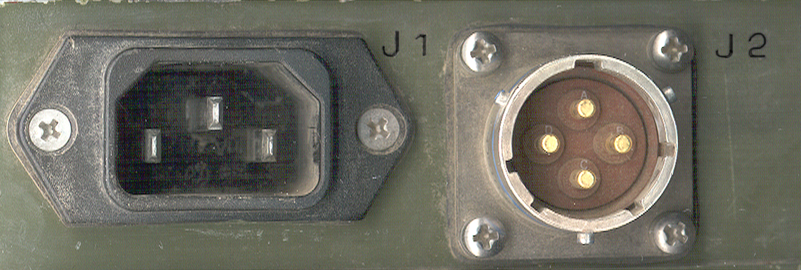
On one end the AC and DC input connectors
If both vehicle DC and line AC are connected the AC line is automatically used. If the line fails auto switch over to DC.
J1 - standard IEC line cord jack like used on most test equipment and computers.
Will accept 90 - 264 VAC @ 47 - 440 Hz
J2 - 4 male pin MS3470W14-4P
A & B = +28 V
C & D = DC return
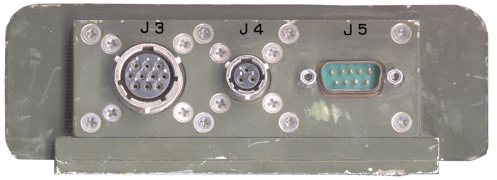
On the opposite end the DC Output Connectors
Sales Brochure errors and omissions
The M449 Series sales brochure is not clear in the paragraph headed "Selection Guide". It mentions three outputs as:
#1 = 32V/3.3A, #2 = 32V @ 1A and #3 = (Battery Charge) @
700 ma. But both connectors J3 and J5 have battery charging
contacts.
So if no battery charging can the full 4 amps be drawn from J4? Can the battery being charged also be connected to J2?
Also how to wire the battery and the thermistors for the battery and
for ambient? What battery to use (Lead Acid, Ni-MH, Ni-Cad and
what voltage (24?) and AH capacity? The connector spec in the
data sheet for J4 has a type it should be -3S not -33S.
J3 and J5 have the same purpose, to charge a 20 cell Ni-Cad
battery. Note 20 * 1.2 = 24 volts. Strange they would use a
24 volt battery in a 32 volt power supply.
J3 - 10 socket MS3470W12-10S
A & D = +32 vdc
B & E = +32 vdc return & battery thermistor -
C = chassis
F = +5 to ambient thermistor
G = Battery Charge +
H = B thermistor +, ambient thermistor -
I = Battery Return
K = n.c.
J4 - 3 socket MS3470W8-3S
May be for driving a printer.
- A = chassis
- B = +32
- C = 32 vdc return
J5 - 9 pin M24308/4-1 (DB-9m)
- nc
- Battery discharge +
- nc
- nc
- battery thermistor
- battery charge + (power from charger here)
- ambient thermistor
- common thermistor
- ground
Battery for J5
NSN 6135-01-361-3886
The positive battery terminal is pin 2 and the negative battery
terminal is pin 9. Inside the battery on the pin 9 leg is a
thermostat that opens the circuit at 80 deg C and recloses at 55 deg
C. For protection from either high ambient temperatures or from
over charging.
The two 10 k Ohm thermistors have a common connection to pin 8 with the
ambient thermistor going to pin 7 and the battery thermistor going to
pin 5.
Between the battery positive terminal and pin 6 is a thermostat that
opens at 3 deg C and recloses at 5 deg C to prevent charging at when
it's too cold.
There may be different amp hour capacity batteries which are identified
by the resistor between pins 3 and 4 of J5. I saw this on a block
diagram of the battery. But M449 J5 shows no connection for the power
supply, so maybe the resistor is used with different chargers?
Back to Brooke's: