Level 0
The lower Aluminum plate that holds the DB-25 plug also has a metal box with three wires going to it, purple is ground and a purple not ground and yellow, most likely a power supply pass transistor. There is a Bendix Scintilla 30 pin socket and all the printed circuit boards have a similar socket with both male and female connection so that they can be stacked. The Bendix part number of this one is 10-299812-30.|
|
|
|
all Up |
|
|
|
|
|
|
|
|
|
|
|
|
|
|
|
|
|
|
|
|
|
|
|
|
|
|
|
|
|
|
|
|
|
|
|
|
|
|
|
|
|
|
|
|
|
|
|
|
|
|
|
|
|
|
|
|
|
|
|
|
|
|
|
|
|
|
|
|
|
|
|
|
|
|
|
|
|
|
|
|
|
|
|
|
|
|
|
|
|
|
1682 +25V |
|
|
|
|
|
L1 IC30 BB |
|
|
|
|
|
|
|
|
|
|
|
L1 IC31a |
|
|
|
|
|
L1 IC31b |
|
|
|
|
|
|
|
|
|
level 1-2 shield level 3&4 can |
|
|
|
|
|
|
|
|
|
|
|
|
|
|
|
|
|
PS xistor term |
|
|
|
|
|
Power Supply GROUND |
|
|
|
|
|
+ 5.2 V main PS |
|
|
Bendix connector has no pins in positions 5, 6, 13, 15, 18, 22,
26, 27
and 28.
All 3 erminals of the PS xixtor are floated from case ground.
Level 1
This lowest PCB contains a mix of ICs and discrete analog components. On the bottom is a MDI Modular model 1682 DC to DC converter with markings, +in, -in, Trim, Oupt, -25V, Com, +25V.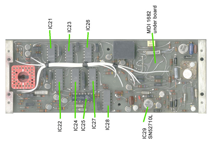 |
 |
The ICs on this baord are marked:
| IC# | # Pins | Marked | Commercial | |
| 21 | 14 | S8870A | ||
| 22 | 14 | S8280A | ||
| 23 | 14 | S8870A | ||
| 24 | 14 | S8280A | ||
| 25 | 14 | NA | 544121n | |
| 26 | 14 | S8280A | ||
| 27 | 14 | S8280A | ||
| 28 | 14 | S8826A | ||
| 29 | 8 TO5 | NA | 52710L | op amp |
| 30 |
8 |
BB |
||
| 31 |
4 |
Blk Plastic box |
Bendix Connector
| Bendix Pin # |
Description Up |
Description Down |
| 1ud |
L4 DC module +25 out L1 DC module +25 out |
" |
| 2ud |
L3 Relay middle |
" |
| 3ud |
|
" |
| 4ud |
L4 DC module common L1 DC module common op amp common |
" |
| 5ud |
||
| 6ud |
||
| 7ud-nc |
L4 Relay 500 coil |
" |
| 8ud-nc |
L4 Relay 498 coil |
" |
| 9ud |
||
| 10ud-nc |
L4 Relay 497 coil |
" |
| 11ud |
" |
L0 PS Gnd |
| 12ud-nc |
L4 Relay 495 coil |
" |
| 13 |
nc |
|
| 14ud-nc |
L4 Relay 501 coil |
" |
| 15 |
nc |
|
| 16ud-nc |
L4 Relay 499 coil |
" |
| 17ud-nc |
L4 Relay 496 coil |
" |
| 18ud=23 |
L1 IC31b |
|
| 19ud |
|
" |
| 20ud |
L4 Relay Coil Common |
" |
| 21d=27 |
open |
L1 IC30 BB |
| 22ud |
L1 module Output |
|
| 23d=18 |
open |
L1 IC31b |
| 24ud |
" |
L0 + 5.2 V |
| 25d=26 |
open |
L1 IC31a |
| 26ud=25 |
L1 IC31a |
|
| 27ud=21 |
L1 IC30 BB |
|
| 28ud |
||
| 29ud-nc |
L4 Relay 502 coil |
" |
| 30ud |
L4 DC module -25 V out L1 DC module -25 V 0ut |
" |
| 31 |
nc |
Level 2
Between level 1 and level 2 is a thin fiberglass board with its ground shield connected by wire to ground. The Level 2 PCB has a mix of 8 ICs and discrete analog components as well as a crystal marked 1M000000 (maybe 1 MHz). Adjacent to the crystal is a glass variable capacitor. There are 8 2N222 transistors each surrounded by a cap, 3 resistors and a diode. and a couple of metal can op amps. |
 |
The ICs on this baord are marked:
|
|
|
|
|
|
|
|
|
|
||
|
|
|
|
||
|
|
|
|
||
|
|
|
|
||
|
|
|
|
||
|
|
|
|
||
|
|
|
|
||
|
|
|
|
||
|
|
|
|
||
|
|
|
|
|
|
Bendix Connector
| Bendix Pin # |
Dexcription Up |
Description Down |
| 1ud |
L4 DC module +25 out |
" |
| 2ud-nc |
L3 Relay middle |
" |
| 3ud-nc |
|
" |
| 4ud |
L4 DC module common |
" |
| 5d |
open |
|
| 6d |
open |
|
| 7ud |
L4 Relay 500 coil |
" |
| 8ud |
L4 Relay 498 coil |
" |
| 9d |
open |
|
| 10ud |
L4 Relay 497 coil |
" |
| 11d |
open |
L0 PS Gnd |
| 12ud |
L4 Relay 495 coil |
" |
| 13 |
nc |
|
| 14ud |
L4 Relay 501 coil |
" |
| 15 |
nc |
|
| 16ud |
L4 Relay 499 coil |
" |
| 17ud |
L4 Relay 496 coil |
" |
| 18ud |
||
| 19ud-nc |
|
" |
| 20ud |
L4 Relay Coil Common |
" |
| 21ud |
L4 caps |
" |
| 22d |
open |
|
| 23ud |
L4 resistors |
L2 741 Out |
| 24d |
open |
L0 + 5.2 V |
| 25ud |
L4 Main top Pot |
" |
| 26d |
open |
|
| 27d |
open |
|
| 28d |
open |
|
| 29ud |
L4 Relay 502 coil |
" |
| 30ud |
L4 DC module -25 V out |
" |
| 31 |
nc |
Level 3 Board A2 CSC p/n C-005
Level 3 and Level 4 PCBs are enclosed in a metal shielding can. The Level 3 PCB has 3 relays and a number of high Q capacitors, a couple of tublar caps marked .99 MFD 100 V.D.C and a couple of smaller ones marked 9100+/- 1% and others marked 91000+/- 1% and many more smaller ones. Two glass piston trimmer caps also on the end of this board.This board only has capacitors and relays, no active components.
 |
 |
The Relay coil common is Bendix pin #20 like on the level 4 board and
the three coils are on Bendix pins 2,3 and 19
| Bendix Pin # |
Description Up |
Description Down |
| 1ud-nc |
L4 DC module +25 out |
" |
| 2d |
open |
L3 Relay middle |
| 3d |
open |
|
| 4ud |
L4 DC module common |
" |
| 5 |
nc |
nc |
| 6 |
nc |
nc |
| 7ud-nc |
L4 Relay 500 coil |
" |
| 8ud-nc |
L4 Relay 498 coil |
" |
| 9d |
open |
|
| 10ud-nc |
L4 Relay 497 coil |
" |
| 11d |
open |
|
| 12ud-nc |
L4 Relay 495 coil |
" |
| 13d |
open |
|
| 14ud-nc |
L4 Relay 501 coil |
" |
| 15d |
open |
|
| 16ud-nc |
L4 Relay 499 coil |
" |
| 17ud-nc |
L4 Relay 496 coil |
" |
| 18 |
nc |
nc |
| 19d |
open |
|
| 20ud |
L4 Relay Coil Common |
" |
| 21ud-nc |
L4 caps |
" |
| 22 |
nc |
nc |
| 23ud-nc |
L4 resistors |
" |
| 24ud |
L4 caps |
" |
| 25ud-nc |
L4 Main top Pot |
" |
| 26 |
nc |
nc |
| 27 |
nc |
nc |
| 28ud |
L4 DC module + IN |
" |
| 29ud-nc |
L4 Relay 502 coil |
" |
| 30ud-nc |
L4 DC module -25 V out |
" |
| 31 |
nc |
nc |
ud-nc means no connection on this level
Level 4 Board A1 CSC p/n C-004
This is the top PCB that has the trimmer pot that can be accessed through the screw in the top outer cover. There are 8 relays on this layer and by each one there are high Q caps. It appears that the main purpose of this board is to switch caps. A MDI Modular model 1682 DC to DC converter is also on this board, +in, -in, Trim, Output, -25V, Com, +25V are the labels. Another of these is on the lowest PCB.There are no ICs on this board only 1 each RCA 2N2905 and RCA
2N2102 (connected as a diode) transistors. The DC module -IN
connection does not show up on the Bendix connector.
| Bendix Pin # all down only |
Description |
| 1d |
L4 DC module +25 out |
| 2d |
nc |
| 3d |
nc |
| 4d |
L4 DC module common |
| 5d |
nc |
| 6d |
nc |
| 7d |
L4 Relay 500 coil |
| 8d |
L4 Relay 498 coil |
| 9d |
nc |
| 10d |
L4Relay 497 coil |
| 11d |
nc |
| 12d |
L4 Relay 495 coil |
| 13d |
nc |
| 14d |
L4 Relay 501 coil |
| 15d |
nc |
| 16d |
L4 Relay 499 coil |
| 17d |
L4 Relay 496 coil |
| 18d |
nc |
| 19d |
nc |
| 20d |
L4 Relay Coil Common |
| 21d |
L4 caps |
| 22d |
nc |
| 23d |
L4 resistors |
| 24d |
L4 caps |
| 25d |
L4 Main top Pot |
| 26d |
nc |
| 27d |
nc |
| 28d |
L4 DC module + IN |
| 29d |
L4 Relay 502 coil |
| 30d |
L4 DC module -25 V out |
| 31d |
nc |