Panasonic KX-TA824 Telephone System
© Brooke Clarke 2012
© Brooke Clarke 2012
This is a small business telephone system that's a favorite on the Singing Wires telephone list server Yahoo Group. That's because is loaded with features and out of the box supports both Panasonic proprietary telephones (PT) as well as old fashioned dial phones. In addition it supports Caller ID on the first three central office outside lines.
I plan on adding a Voice Over Internet Protocol (WIKI: VOIP) capability so that I can make free long distance calls. Note: my cell phone has no signal at my house and even with the repeater only has a couple of bars when the phone is located in the SpotWave Z1900 cell phone repeater hot spot. The Magic Jack was the early low cost VOIP solution but there are now others.
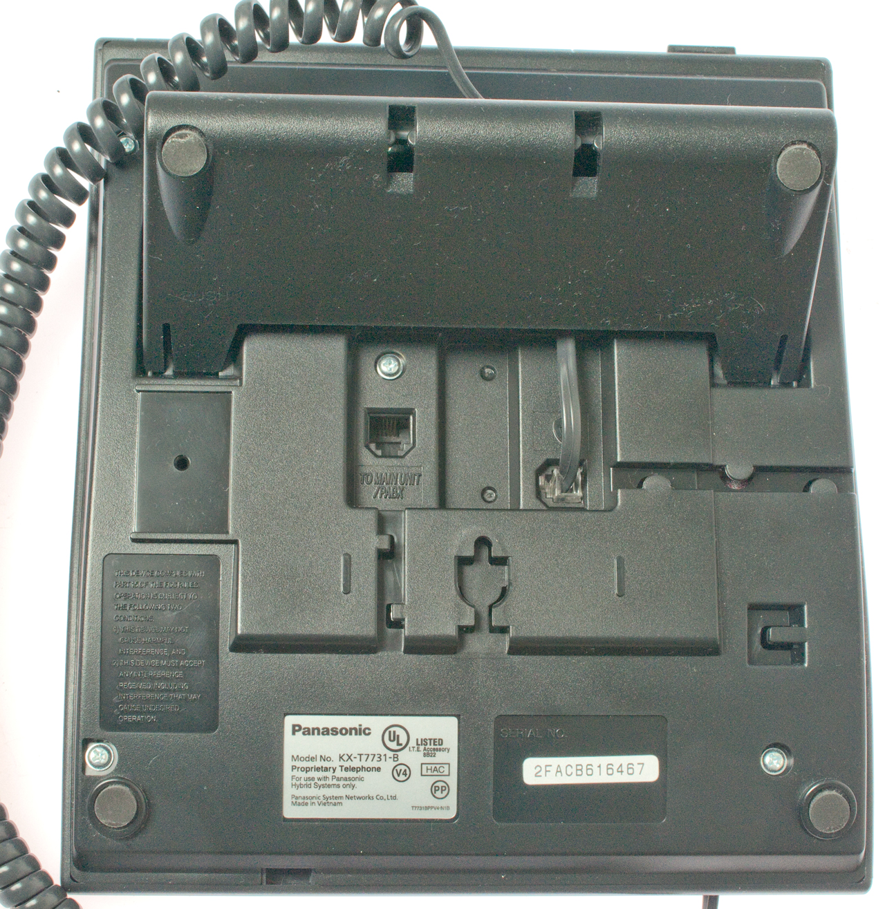
The serial number starts with 2F which I've been told means this unit was made in 2012.
The key idea is that I can choose which outside line (home phone copper line, fax copper line or VOIP line) to use depending on where I'm calling.
2016 update. This is working very well. My long distance bill has gone to near zero (sometimes a guest uses the wrong line). Google Voice still is the VOIP provider and their international rate is 1¢ per minute. Domestic calls are free. There can be a problem if someone is watching Netflix while another tries to make a VOIP call since my download speed is only 2.2 Mbits/sec.
| Fig 1 |
Fig 2 |
Fig 3 |
||||||||||||||||||||||||
(Fig 4 same as) Fig 5 Options
(CID 1 is in stock unit)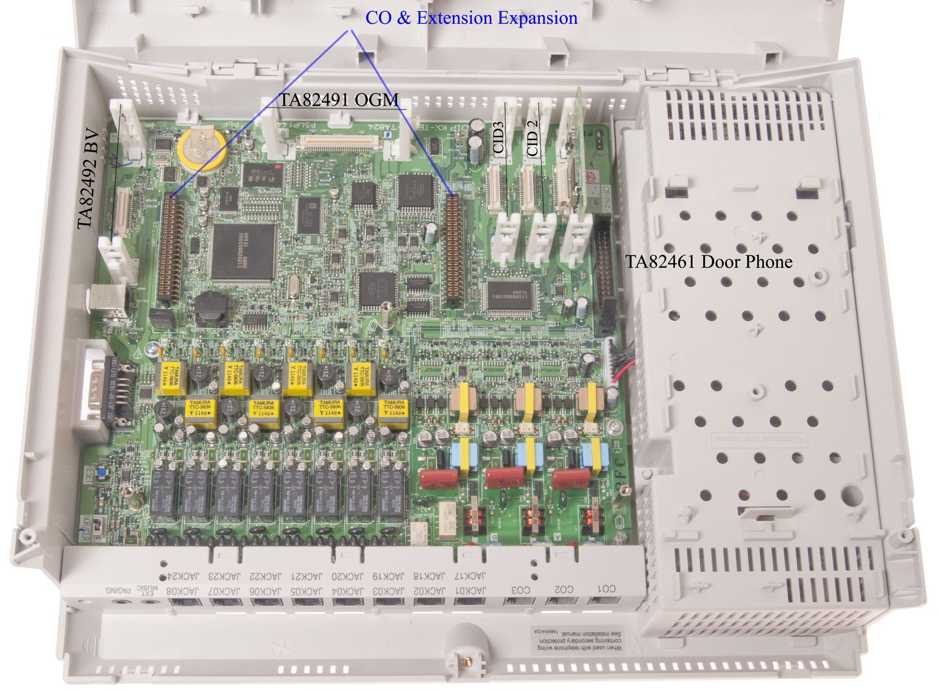 |
Fig 6 Caller ID CID Card KX-TE-82494/TA82493/TE82493 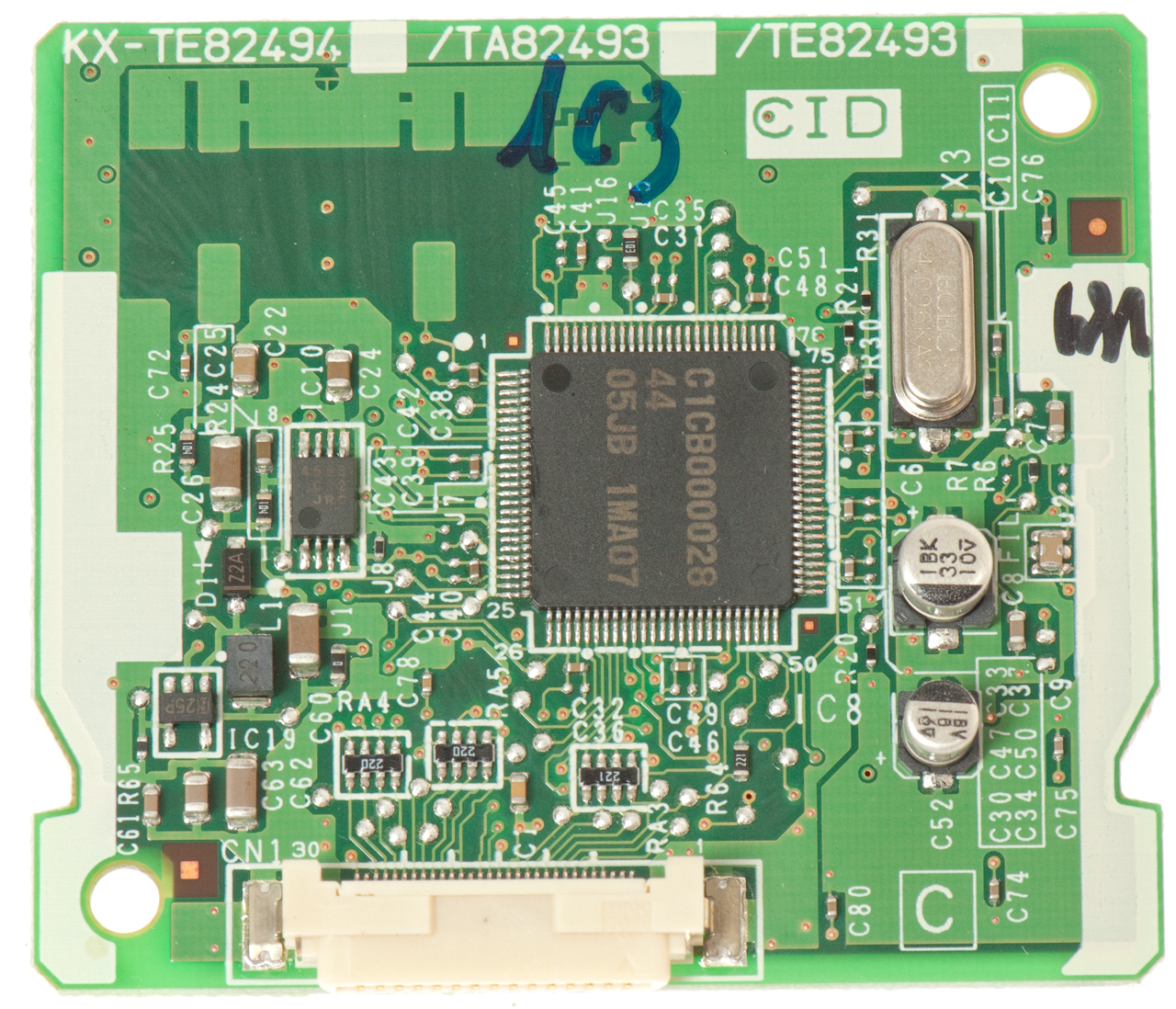 |
|||||||||||||||||||||||||
Fig 16 with 8 CO lines & 24 Jacks + CID
on CO1 through CO6 (not needed on CO7 & CO8) |
||||||||||||||||||||||||||
| Fig 7 Out Going Message OGM
card KX-TE82491/TA82491 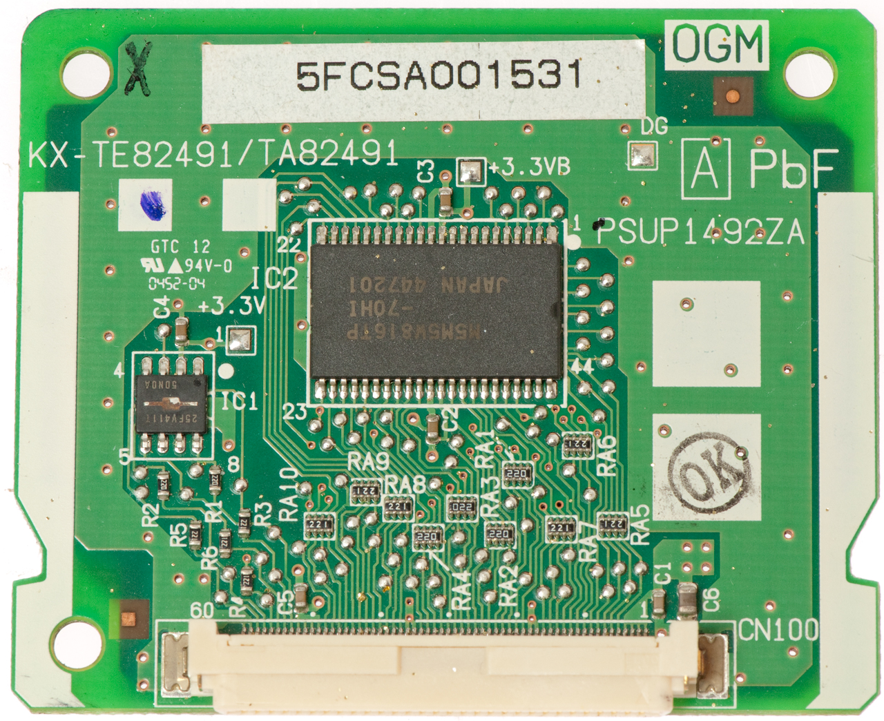 |
Fig 8 Built-InVoice 2-Channel
Message Card (BV) KX-TA82492 8AASA003502 UPC: 0 37988 85141 6
Initialization Instructions
|
|||||||||||||||||||||||||
Fig 9 Pre-wired board
installed on garage wall
 |
There needs to be space below the KX-TA824 to allow the lid to open. The supplied mounting screws have a shoulder and a washer and when the screw is turned until it seats on the washer the gap between the top of the washer and the underside of the head is just right for a snug fit to the KX-YA824. Prewiring: CO1, CO2 and CO3 at the upper right. J01 and J02 at the left with J01 using the first two pair of the 6 pair cable. The 6-pair cable can be seen at the right of the board and going through the wall at the bottom which comes out at the NID out the outside wall. PS the equipment below the backboard is a GRC-206 in it's MT-6250 mount. |
|||||||||||||||||||||||||
Fig 10 Close Up of J01
on 66 Block
|
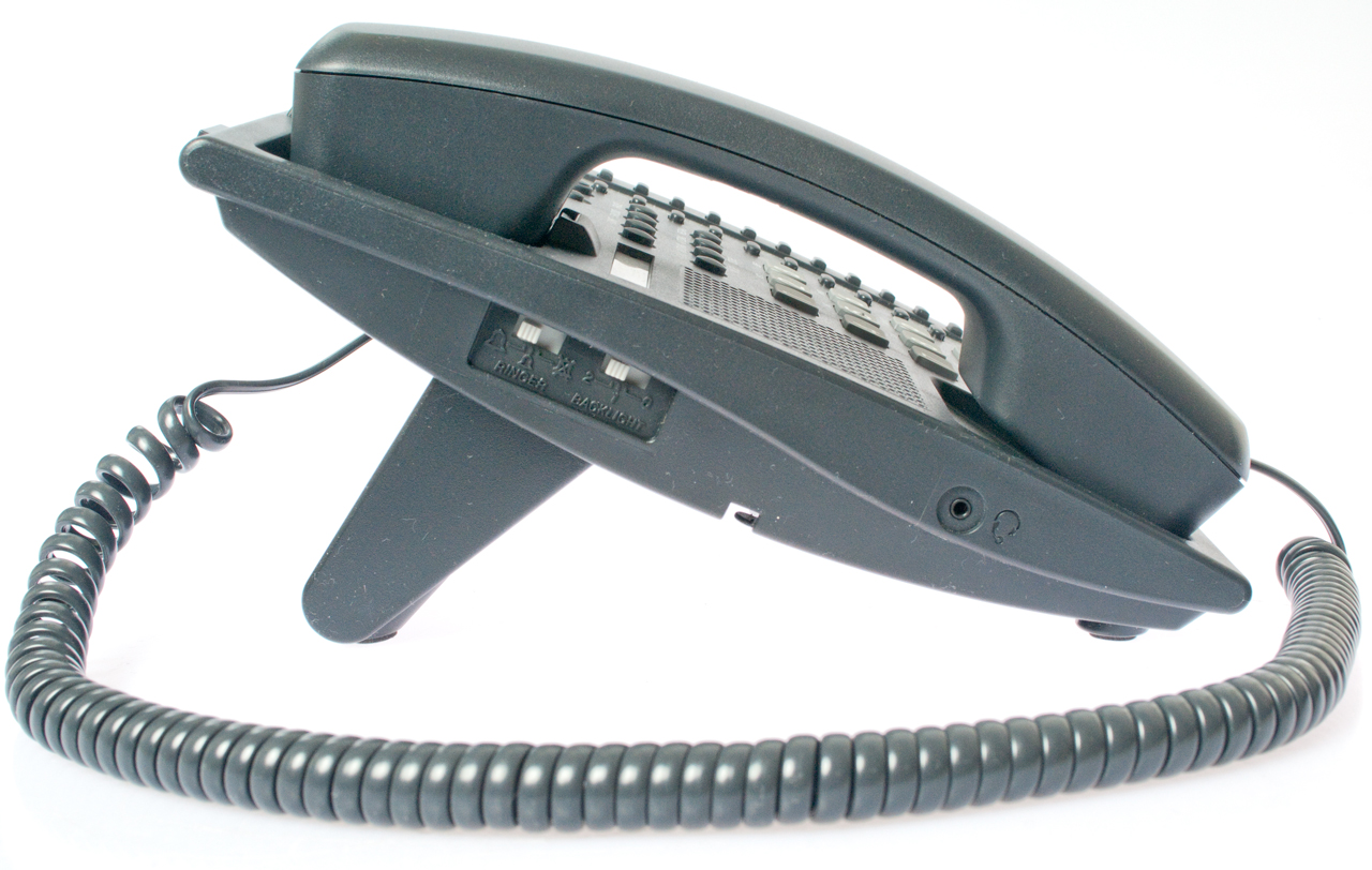
Fig 11 KX-TA824 working with KX-T7731 PT The DSL spliter/filter is connected and feeding office jack 4 -> computers & VOIP working.  |
Fig 11a - 5 Feb 2013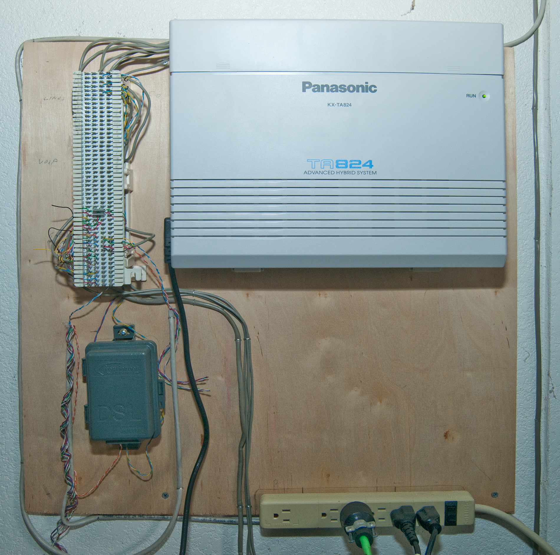 Still has no optional line cards.
|
||||||||||||||||||||||||
Fig 12 KX-TA82481 2x8
extension card top Note: This is the second line card used for CO7, CO8 and Jacks 17 to 24. In order to install this card I need 2 multi-contact spacers with guide pins and 3 each 3-0.5 x 5 mm screws (found the screws). Where to get the multi-pin connectors? Ans: Panasonic Parts (800) 833-9626 p/n: K1KA40A00234 (order 2 each) |
Fig 13 KX-TA82481 2x8 extension card bottom |
|||||||||||||||||||||||||
 with the 2 riser
connectors installed. with the 2 riser
connectors installed. |
||||||||||||||||||||||||||
Fig 14 3x8 KX-TA82483 Kit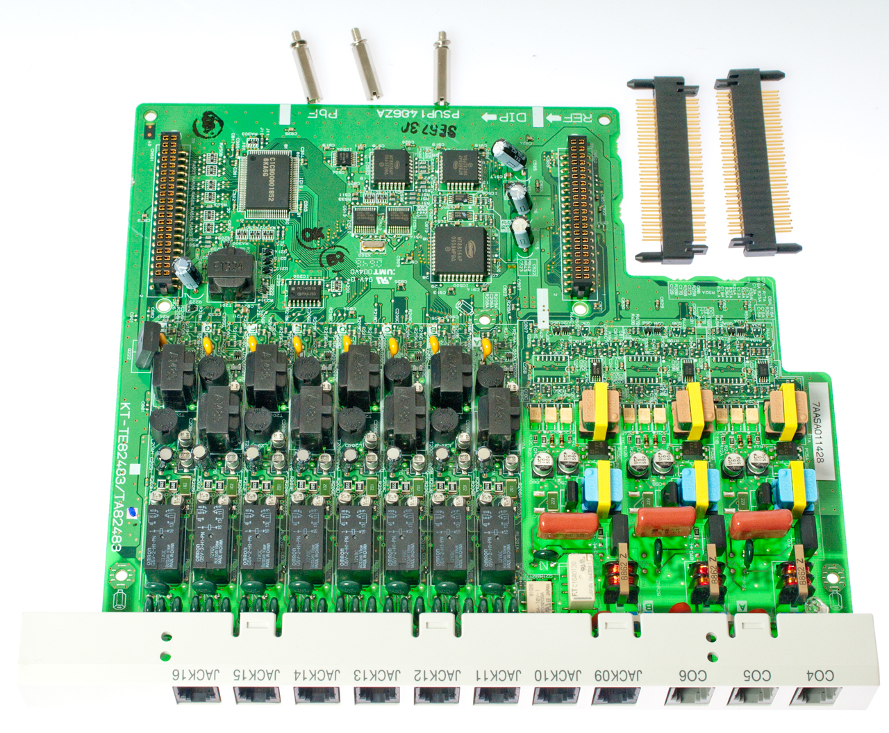 Note: This is the first optional extension card for CO4 to CO6 & J09 to J16 |
Fig 15 3x8 KX-TA82483 Box |
|||||||||||||||||||||||||
Fig 16 KX-T824 with KX-TA82483 3COx8Jack
Expansion Card Installed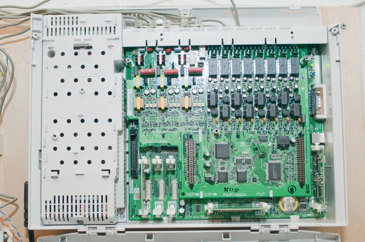 Note 1: the two spacer Plug-Jacks are installed first with the locating pins up that makes it easy to align all the pins. Note 2: The VOIP CO line has been unplugged from CO3 and installed in CO6 and while I'm writing this will move CO2 to CO4 as part of the power fail configuration. |
There are some aspects of operation that you need to be aware of.:
Power Fail
One central office line (CO1) is connected to an extension (Jack 01) in an 8 line system. When more extensions are added the lowest numbered CO line is connected to the lowest jack number on that card (CO4 to Jack 09, CO7 to Jack 17). This means that for each line card there are two CO lines that are NOT connected when the power fails.
It may make sense to use relays with AC coils that are pulled in when AC is present and in that state connect the CO lines to the KX-TA824 and when AC fails each relay disconnects the KX-TA824 (it may be that in a power failure the PBX has open outputs) and connects a CO line to an extension line.
Manager
The system manager functions only work on Jack 01 so this is where the Proprietary Telephone (PT) should be if there's only one of them.
VOIP
The VOIP hardware should be near the Back Up Power Supply so it will keep working during a power failure. But the KX-TA824 is best located in the garage near all the phone lines.
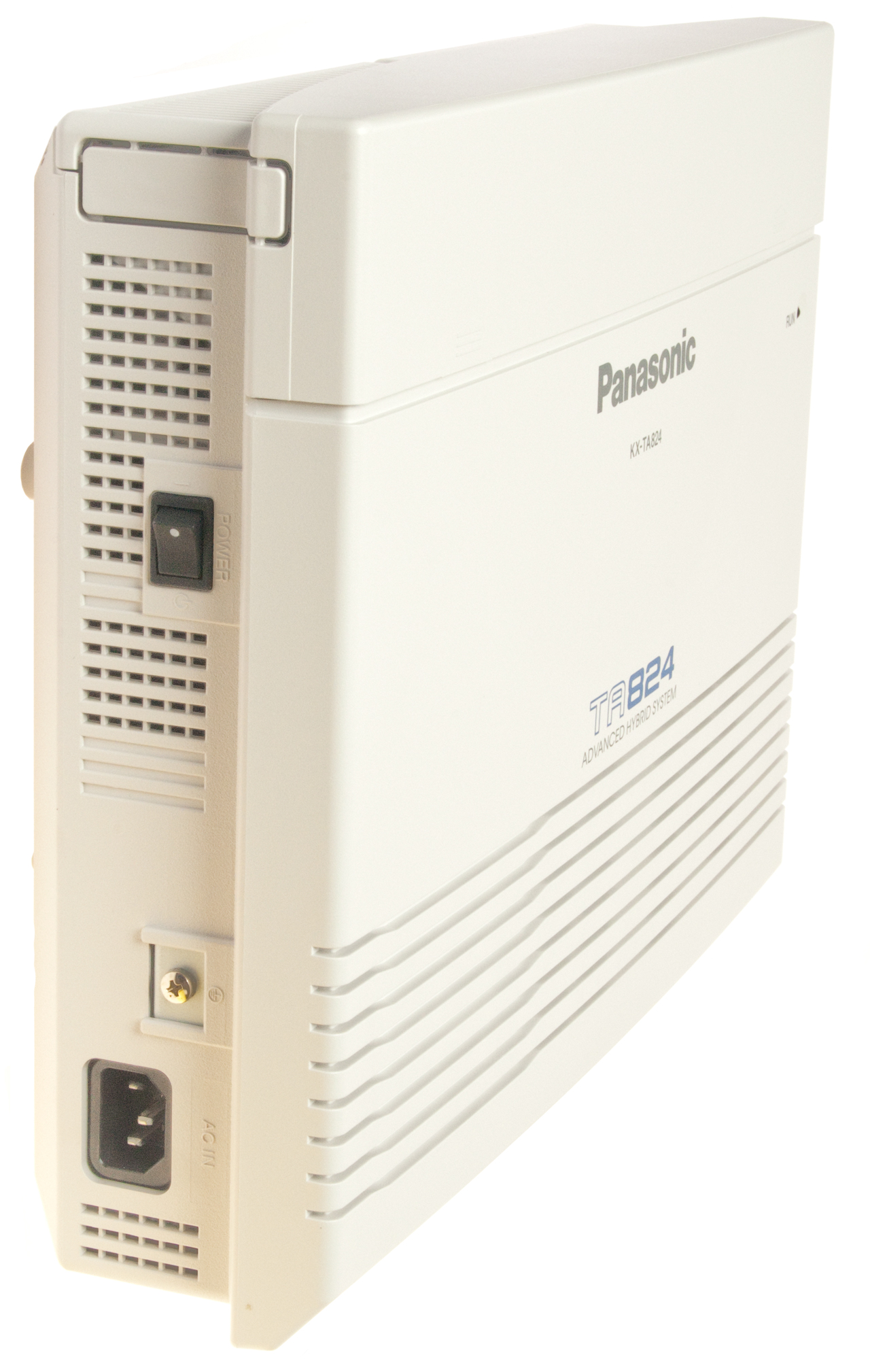
KX-TA824
This is the PBX box. It comes with the capability of handling 3 Central Office (CO) lines and 8 extension jacks on the motherboard. Also included is one Caller ID (CID) plug-in board that works for CO lines 1, 2 and 3.
Possible Options
Model
Name
Details
KX-TA82483
Line Card
CO4 - CO6 & Jack09 - Jack16
KX-TA82481
Line Card CO7, CO8 & Jack17 - Jack 24
KX-TA82470 Line Card Jack09 - Jack16 or Jack17 - Jack24
KX-TA82493
Caller ID
CID1: CO1-CO3, CID2: CO4-CO6, CID3: CO6-CO8
KX-TA82461
Door Phone (4 port)
KX-TA82491
OGM DISA SMDR
allows two outgoing messages plaid at same time
KX-TA82492
BV
allows up to 60 minutes of Built-in incoming Voice message storage
KX-TVA50 Voice Processing System
T?
System phone that has CID announce by voice
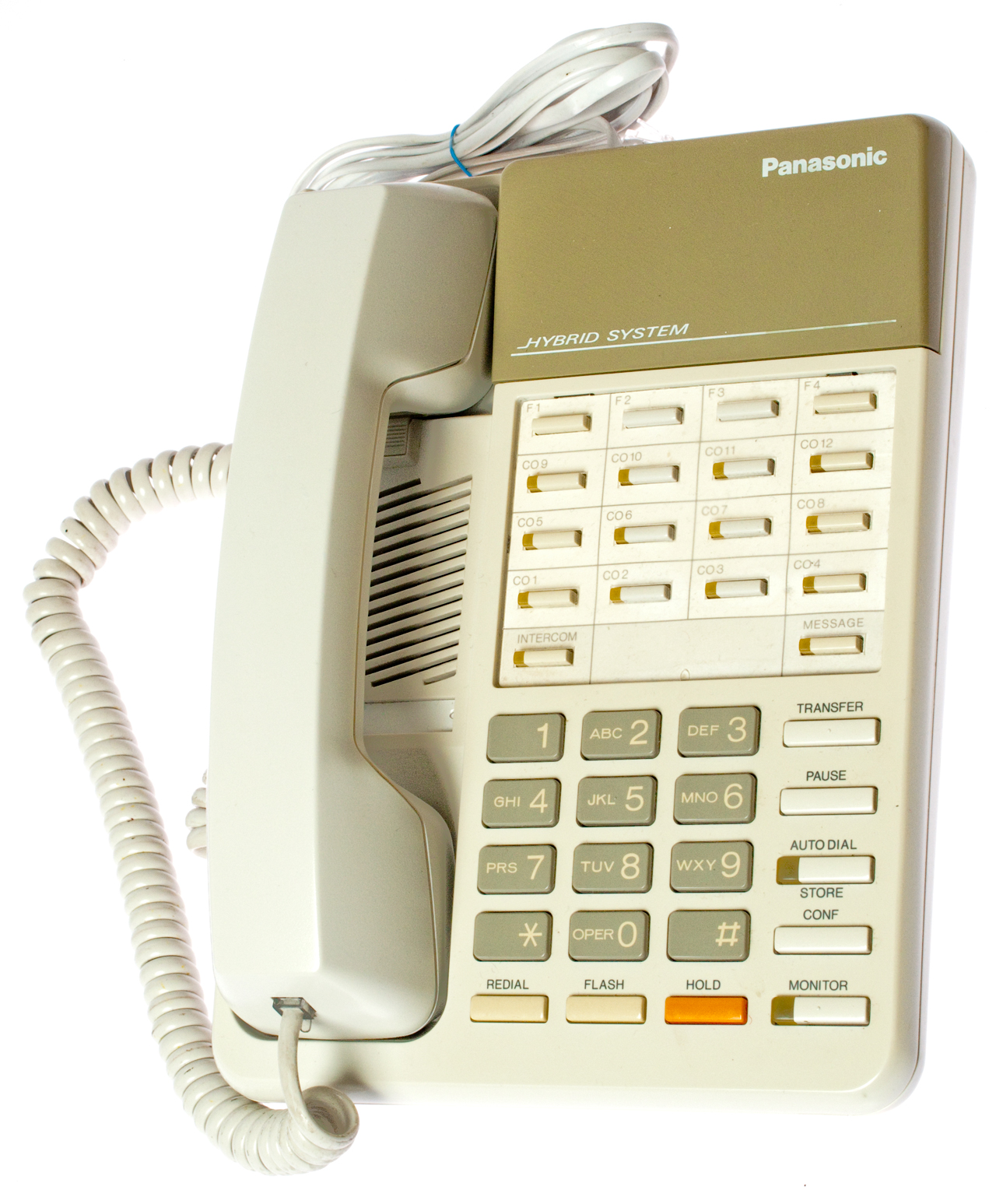
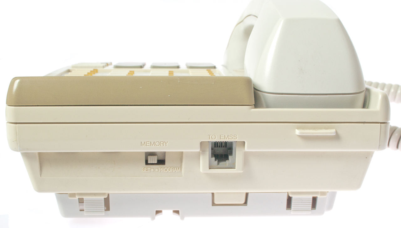
KX-T7731 Proprietary Telephone (PT)
Parallel Telephone
You can not connect two proprietary telephones to the same extension (jack) and have them both work even when the jack has been programmed for parallel telephones.
If you connect a PT in parallel with a SLT (on the same jack) then only the PT phone will ring, the SLT will not ring.
But you can connect a Single Line Telephone (SLT) (plain old telephone) to the same jack as a Proprietary Telephone (PT) and after using program 610 "Paralleled Telephone:: enable) for that jack number both phones will ring.
PT phones will not work during a power failure, so if you have a PT on jack 01, 09 or 17 it would be a good idea to also have a parallel Single Line Telephone in parallel so it will ring on incoming calls and be able to dial out.
Single line LCD.
Shown with the bottom CO line active (with dial tone) with speaker mode on.
When connected to Jack 01 this phone has special "manager" features. It also can be used to program the KX-TA824 or a USB or RS-232 connection to the PBX can program it.
KX-T7050
No LCD. No Auto Ans.
KX-T7735
Similar to the KX-T7731 except has a 3 line LCD.
KX-T7736
Similar to the KX-T7731 except has a 3 line LCD.
Table of Advanced Hybrid Compatible Phones
These are all Proprietary Telephones (PT).Not tested, just from surfing the web.
Model
CO Lines
LCD
lines
Features
KX-T7020
12
0
speakerphone
KX-T7030 12
1
speakerphone KX-T7050 12
0
speakerphone KX-T7130
12
1
speakerphone KX-T7135 12
1
speakerphone KX-T7320 12
0
speakerphone KX-T7335 12
3
speakerphone KX-T7350 12
0
speakerphone KX-T7720 12
0
speakerphone KX-T7730 12
1
speakerphone KX-T7731 12
1
speakerphone KX-T7735 12
3
speakerphone
auto answer
KX-T7736 12
3
speakerphone
auto answerKX-T7740 48
0
48 buttons/32 lamps
KX-T7750 12
0
-
KX-T61620 12
3
speakerphone
auto answerKX-T61630 12
?
speakerphone
auto answerKX-T61650 6
0
-
KX-T123220 12
0
?
KX-T123230 12
1
speakerphone KX-T123250 12
0
speakerphone
The system is on order (25 Nov 2012) as well as a KX-T7731 system telephone. It will be installed on the inside garage wall near where the phone lines now go through the wall to the outside box. Those wires can be routed to come out the inside garage wall and terminated on a punch down block with a cable to the KX-TA824 system.
A map of the house needs to be made showing the phone outlets and which wires go to which outlet.
The VOIP box needs to be connected to the at&t DSL modem (rather than the old fashioned USB connection of the first generation Magic Jack) and the other end connected to one of the now unused pairs on the 6 pair home run cable (using pair 5). This will connect to the third CO line on the KX-TA824.
There's a problem when connecting CO2 or CO3 in that the real CO or the VOIP phone port do not have dial tone. If the VOIP phone line connection to the CO input of the PBX has the polarity reversed it will not work Positive on the green wire (Red is Ring, Green is tip) to the PBX.
9 Jan 2013 - Dialing:
81 gets to the main house phone line
82 should connect to the voice side of the DSL line. This works on the system phone by pressing the CO2 button, but not on other phones pressing 82.
83 gets to the VOIP line
Note: on the system phone program 400 shows "connect" for lines 1, 2 & 3.
Assigning Central Office Lines
When you dial 9 for an outside number the KX-TA824 starts looking at the highest numbered CO line (CO3 for a stock system, CO6 for a system with one optional line card ( and CO8 for a system with the second optional line card (2x8 KX-TA82481). In my case I'd like the free to all of the US VOIP line to be used so it's connected to CO3 on my stock system and will be connected to CO6 when I get the optional 3 CO x 8 extension line card.
The most used incoming line, in my case my home phone line, is connected to the lowest numbered CO line (CO1 in this case).
By dialing 81, 82 or 83 you can select which CO line to use for outgoing calls (home phone, FAX/DSL or VOIP).
Assigning Extension (Jack) numbers
When the power fails on a stock system CO1 is connected to Jack01 (extension 101).
In a system with one optional 3x8 line card CO4 connects to Jack09 (extension 109) in addition to the CO1->J01.
In a system with two optional line cards CO7->J17, CO4->J09 & CO3->J01.
Ref: Features Manual pg 129 para. 1.1.102
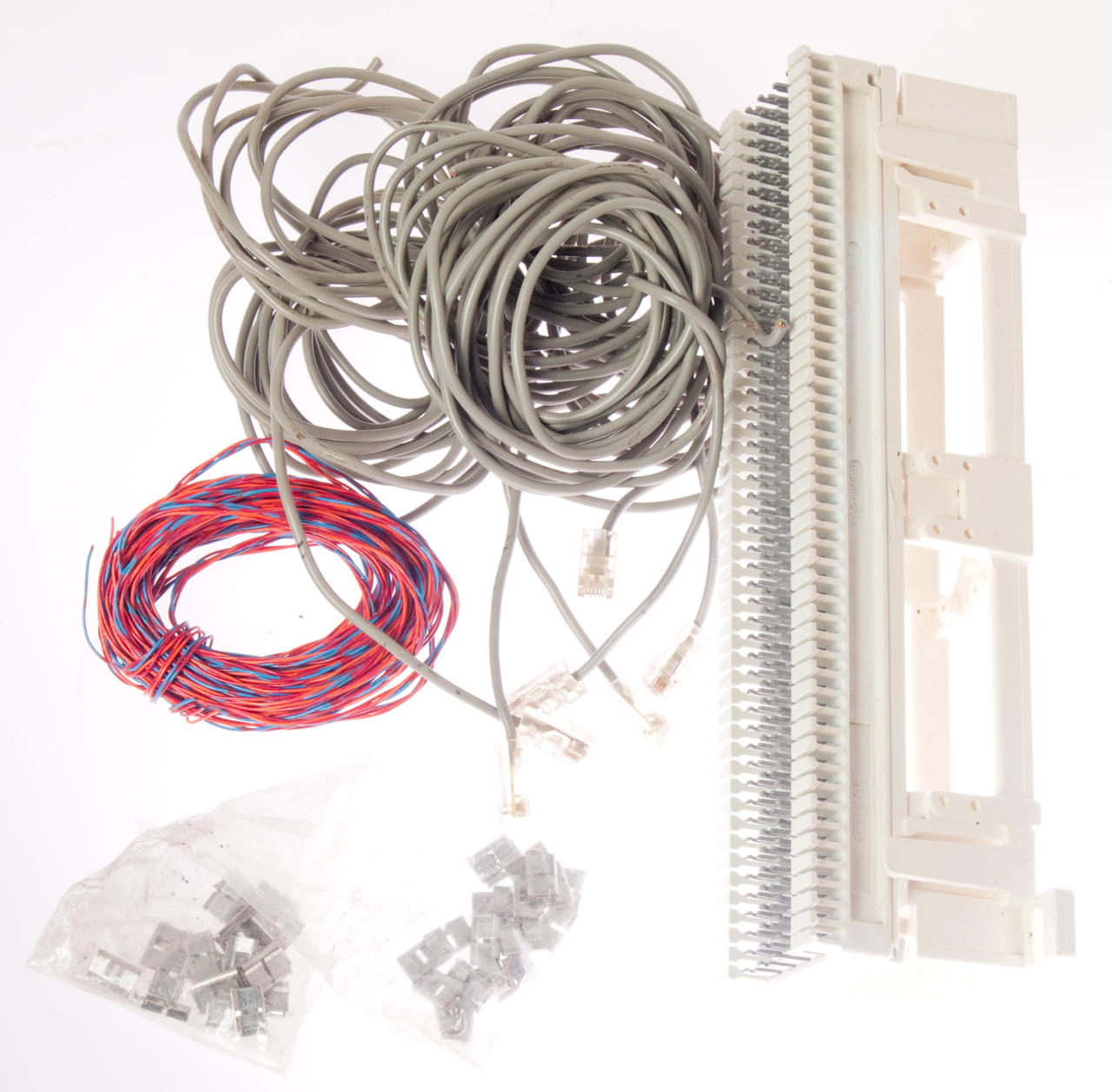
I bought a kit of parts so that a 66 type block can be used to terminate the CO lines as well as the interior house phone lines.
66M1-50 telephone punch down block, 89 bracket and related parts
Wiki: Punch Down Block, 66 Block
6 each solid wire cables w/ RJ-11 on one end
some cross connect cable (single pair)
a 66M1-50 block & 89 bracket
a bunch of 66 block jumpers.
66M1-50 Punch Down Block
Each of the 50 rows has 4 punch-down terminals but they are not all electrically connected.
The left 2 terminals are connected and the right 2 terminals are connected.
The jumper clips could be used to make an electrical connection between terminals 2 and 3. That would suggest that the CO lines and station wires are terminated on terminals 1 and 4.
The 66M1-50 punch down block is marked CAT5 and U.S. Pat. No. 6,010,372.
6010372 Cross-talk reduction mounting block for connectors, Communications Systems, Inc., Jan 4, 2000, 439/712 -
To make a connection between the 66 block and the RJ-11 modular connectors on the PBX you need a solid wire cable, not a stranded wire cable because 66 blocks only work with a single solid wire on each terminal. Note that the common 6P2C or 6P4C connectors sold in the local hardware store are designed for stranded wire (Wiki)
These can be used for either telephone or LAN cabling. My interest is because by adding a hard wired LAN connection between the router (at&t DSL 2wire) and my TV or Blue-ray player the quality of Netflix streaming videos has very noticeably improved.
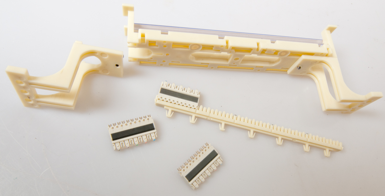
Each of the electrical terminals in the small connecting block are insulated from the adjacent terminals. Connections are made from fixed wiring at the bottom to cross connect wiring at the top. See:
http://www.siemon.com/int/download/installation_instructions/us/110_S110AW2-100_ii.pdf
It turns out that this sort of works for CAT5 but does not work for faster speeds where the building cables are terminated in jacks at both ends and a switch is used at the hub.
A possible switch is the Linksys Cisco 16-Port + 2 Gigabit Switch SRW2016 or something similar.
This is intended for use with the RJ-45 jack LAN wiring, but the common RJ-11 phone plug works. Just wire to terminals 4 & 5 (Blue/White).
In a bag that looks almost identical you can get either 8p8c RJ-45 LAN jacks or 6P6C voice grade telephone jacks that fit the modular wall plates.
Can be used to terminate the 6 pair in the home run cable between the NID and my office.
There is not any quad wire (red-green, yellow-black) here.
The DSL router and the Obi 110 VOIP boxes are located in the office and powered from the UPS and both need home run wiring to/from the PBX.
from Home Depot
plate: Tech 615 723, No. 5006-WH
UPC: 660559009116
Bag of 10 RJ-45 LAN Jacks: Tech 635-416, No. 5015-WH-10,
UPC: 660559009628
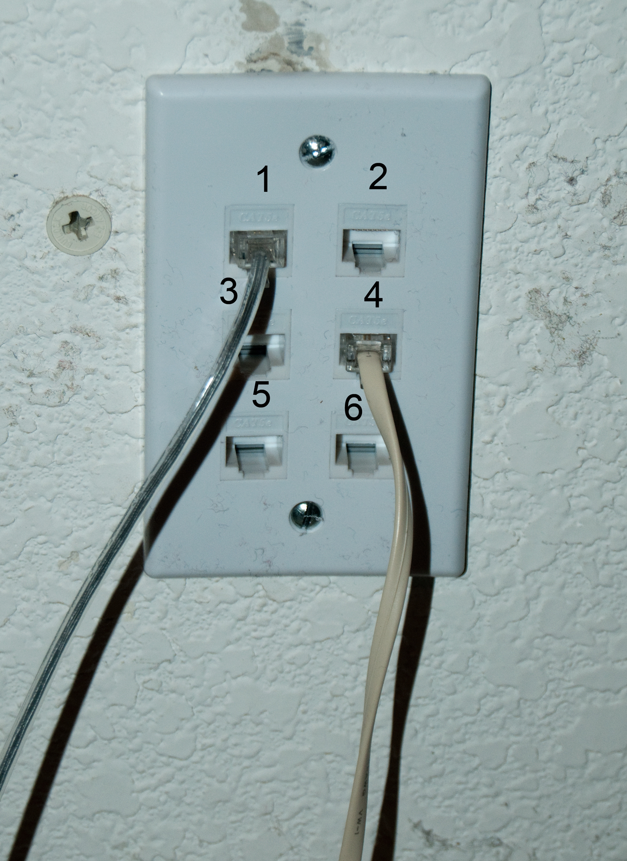
Each of the 6 pairs that make a home run to the NID box
are terminated on this plate.
The line assignments are as found.
Jack
Description
1
Home Phone
2
3
4
Combined DSL & Phone - cord goes to DSL splitter.
5
6
Wiki: Registered Jack, TIA568,
Note: It's OK to use an RJ-11 plug in an 8p8c jack for phone use, but it may
be a problem if the same jack is later used with an 8p8c plug because the outer
jack contacts may be deformed by the sides of the RJ-11 plug.
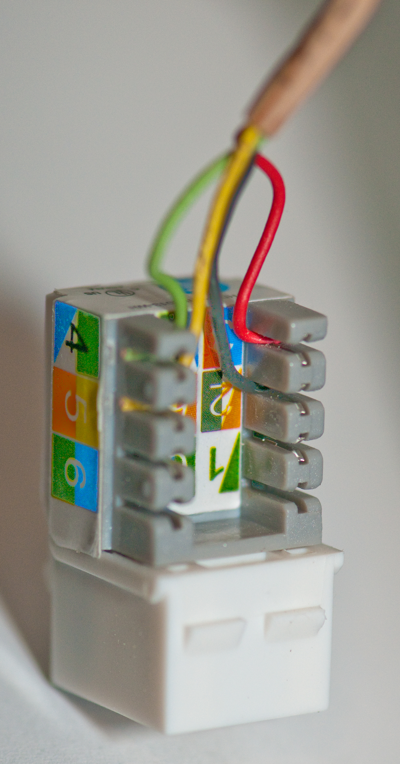
Quad Telephone Cable (2 Pair) Plug Color Order
Bad Redheaded Girls Yell
Quad Telephone Cable (2 Pair) Jack Color Order
This is called a Keystone Module (Wiki) it fits into a Keystone Wall Plate.
The Wall plate is mounted on a low voltage drywall ring.
There are two kinds of 6P4C plugs: 1) the kind stocked at Home Depot designed for stranded wire,
and 2) the kind made for solid wire round cables, like above from eBay
This oneInternet # 203579138 says it's for either solid or stranded?
There are a number of RJ-series jacks at Home Depot.
Both for various flavors of LAN and for Telephone use
that all fit the various wall plates with various numbers
of holes.
Leviton also makes a number of White Single Gang wall plates and jacks and some of them are stocked at Home Depot. They also have white 5e Jacks, Voice grade jacks, Type-F coax, speaker terminals etc.
They also make a 66 block with mounting bracket @ (Home Depot $20, SKU # 162677 ).
eTech
Wall Plates (CE Tech at Home Depot)
Jacks
# Holes
Color
SKU
1
Wht
579644
2
Wht
595177
3
Wht
598515
4
Wht
614029
6
Wht
615723
Hole Filler
Wht
620740
6-32x1/2" Screw
Wht
95174
Category
Config
Color
Qty/bag
SKU
5e
8P8C
Wht
25
636303
5e
8P8C
Wht
10
631078
Voice
6P6C
Wht
10
624865
Type-F
Coax
Wht
10
618650
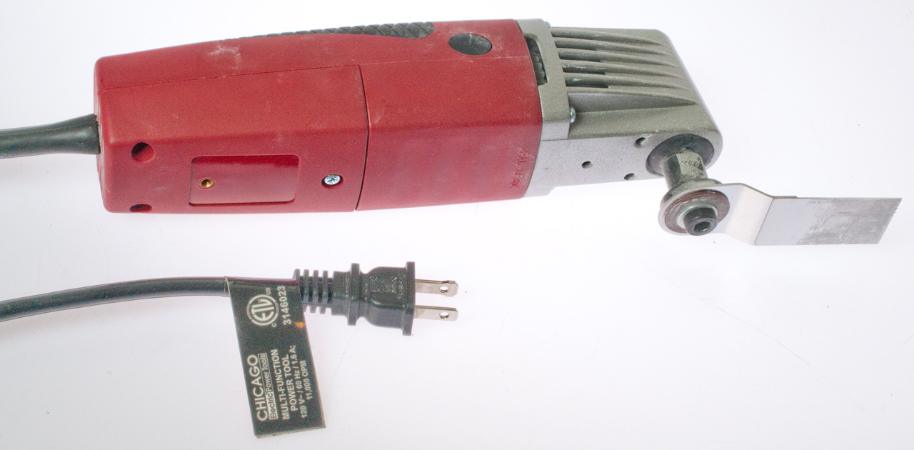
Harbor Freight 3146023 - Multi Function Power Tool
Great for cutting Sheetrock (drywall) to install the low voltage ring.
Item # 68861
With Plunge Cut Blade Item # 68904
What's needed is a template for the hole.
Note: The Carlon SC100RR has 4 holes for marking the wall opening.
Highlighted in black in the below photo.
Also Note: the ears need room to open so do not position opening too close to framing.
Low Voltage Drywall (Sheetrock) ring - Old Construction
Home Depot Store SKU # 750544
Carlon SC100RR-CP
"Low Voltage 1 Gang Bracket Mount Multipurpose DryWall WallPlate"
Video showing installation of Carlon SC100RR for new phone jack
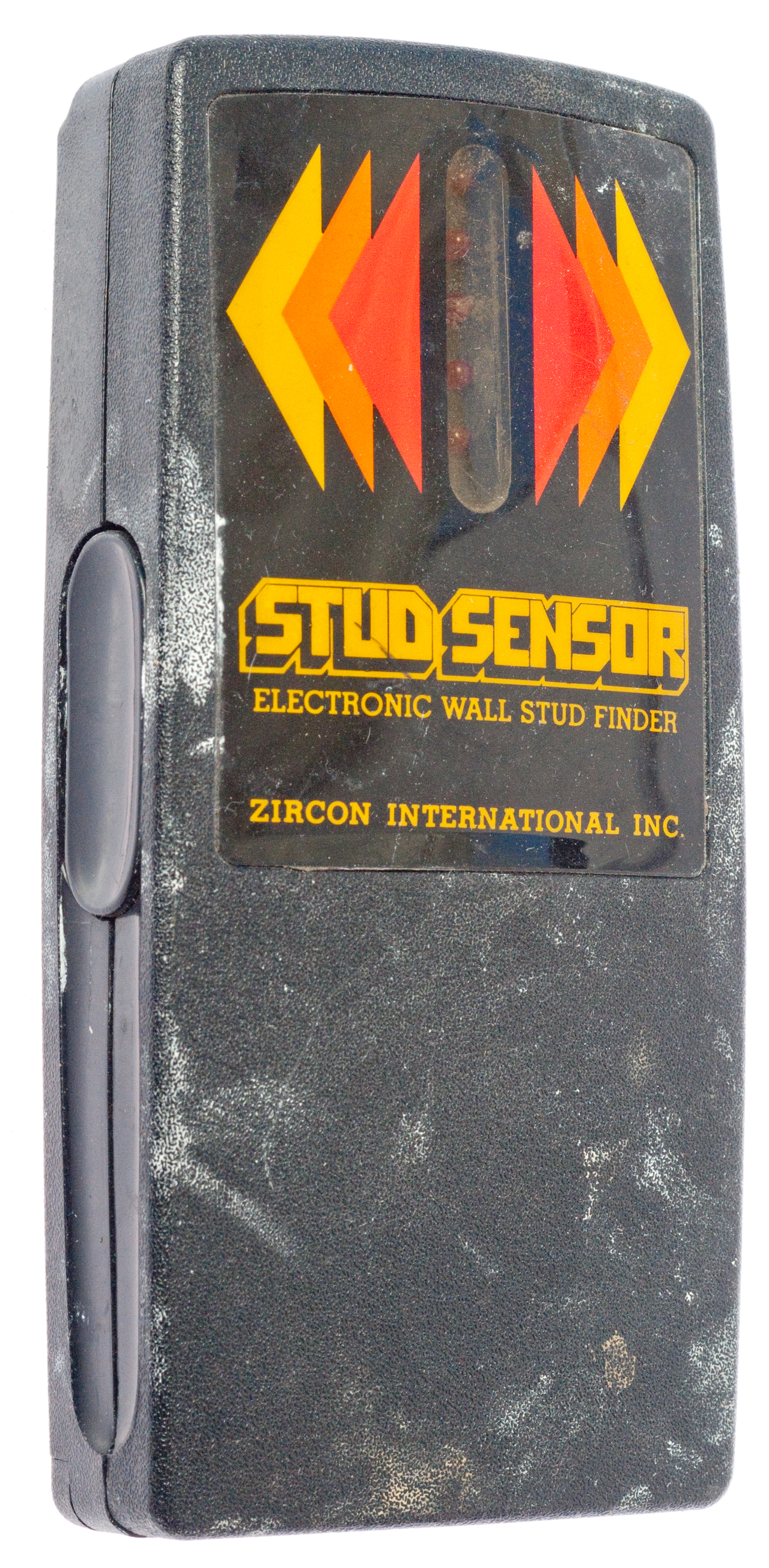
Zircon Stud Sensor
These are very handy when working on dry wall. This one's seen a lot of use.
4099118 Electronic wall stud sensor, Jul 4, 1978
24 April 2013 - there was a power failure at 1:21:45 am that lasted for 10 seconds. This was reported by the backup system for my computer.
In the morning I tried to use the phone and it was dead. The LCD back light was out. The green LED on the system box was out.
Cycling the power switch and unplugging the box did not turn on the green LED.
The power fail pass through works and some phones are working.
The power supply can be accessed by removing 3 screws. But if the box is disconnected and removed for service the phone pass through will be broken, so I need to get some RJ-11 female-female couplers before removing it from the wood panel.
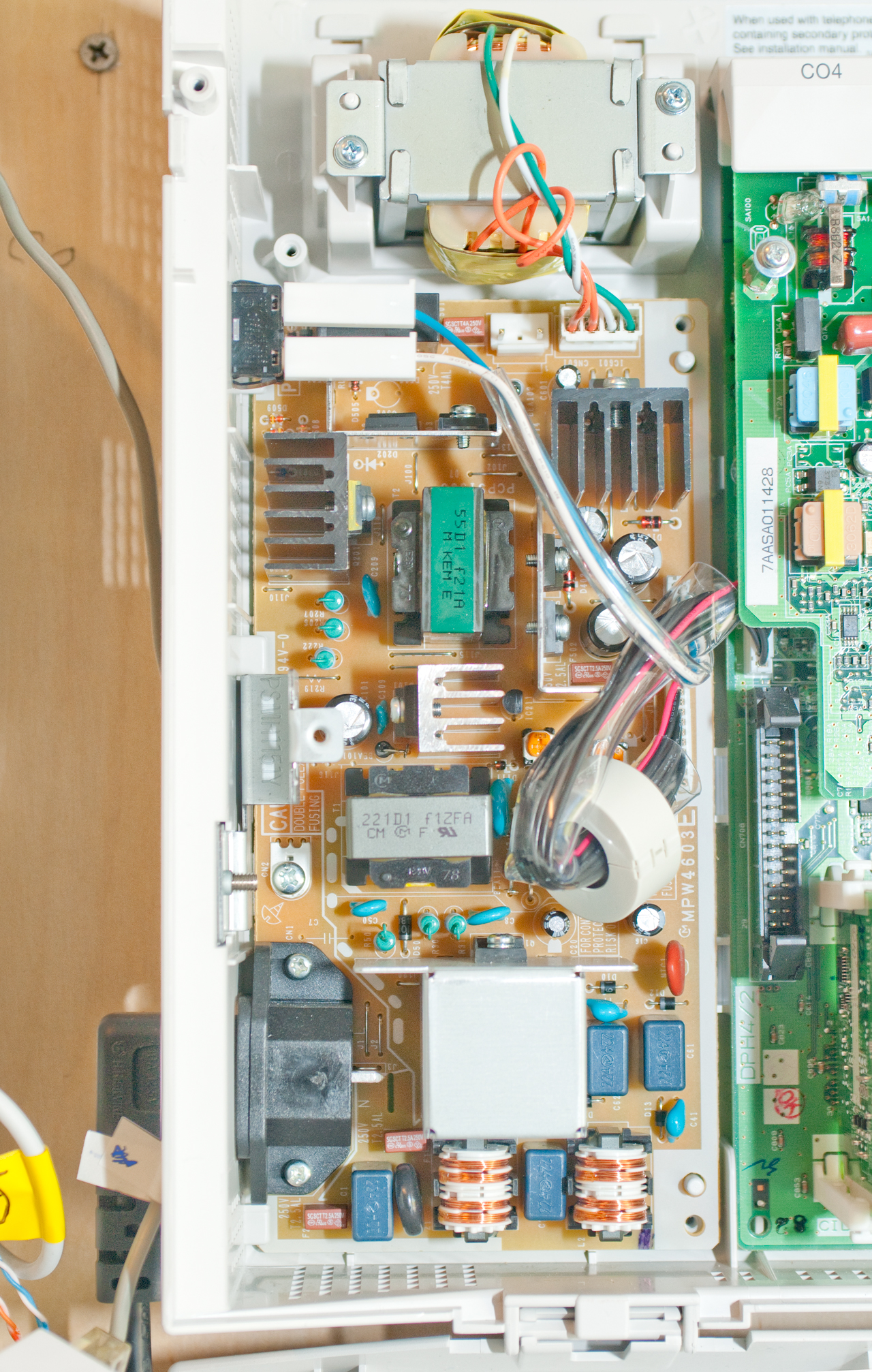
Cover Removed showing Power Supply on left
Notice:
female-female coupler between CO1-Jack01, CO2-Jack09
Power Supply - Backup Battery ?
Note connector just below the center of transformer,
just to the left of the 4 wire (org, org, wht, grn) connector.
It looks to me like it is for a (lead acid) backup battery.
Let me know
This may be a standard three socket 0.1" header with the center socket not used.
The AC mains gets rectified to DC then switched prior to T1.
The output of T1 is a 27 VDC supply.
So the external backup battery is is probably a 24 Volt lead acid type.
Note when charging a "24 Volt" battery is at about 28 VDC.
The 27 VDC rail drives a switching mode power supply that generates all the other voltages needed.
It may be that Panasonic never did the US certification for the backup battery so it's not talked about on US equipment. They did make a cable (KX-A227) to connect to a series wired pair of 12 Volt batteries.
The GFI outlet which feeds the power strip seemed to break the connection if the top plug was wiggled, so I replaced it prior to removing the KX-TA824 box for troubleshooting. Prior to this I had plugged the outlet strip into the bottom socket and it was powering other equipment so I'm very sure the outlet strip was hot.
After the GFI outlet replacement I powered up the KX-TA824 and it came to life. The only thing I can think of is it was without power long enough for the power supply capacitors to drain down enough so that when power was applied it did a cold start. This is why tech support often says remove power for a minute or more before applying again.
So far I think all the programming is intact. I did not do a reset since the backup battery will hold the programming for a long time. The long wait worked in a way similar to doing a reset.
Can the KX-T824 run from the modified square wave output of an AN line type UPS? Let me know
When the AC mains power fails each line card makes a connection between the lowest numbered CO line and the lowest numbered extension.
X101 is typically used for the system telephone that's used to configure the KX-T824, but it's also possible to connect a plain old telephone to the same extension. I have done this and am able to make and receive calls even though my house AC power is off.
CO1 X101 CO4
X109
CO7
X117
From TX-T7050 Telephone. None of them are assigned to Panasonic (must have been purchased from the inventor). They all relate to using micro controllers with machine tools, not telephone specific.
1122290 Junction-board, Hereward M Mack, Wallace P Andrick, General Acoustic Co, 1914-12-29, - a precursor to the 66 Punch Down Block
4120583 High registration photomask method and apparatus, Gilbert P. Hyatt
4121284 Computerized system for operator interaction, Gilbert P. Hyatt
4371923 Computer system architecture, Gilbert P. Hyatt
4396976 System for interfacing a computer to a machine, Gilbert P. Hyatt
4531182 Machine control system operating from remote commands, Gilbert P. Hyatt
4686622 Computer system architecture using serial communication, Gilbert P. Hyatt
4825364 Monolithic data processor with memory refresh, Gilbert P. Hyatt
4829419 Microcomputer control of machines, Gilbert P. Hyatt
4896260 Data processor having integrated circuit memory refresh, Gilbert P. Hyatt
4942516 Single chip integrated circuit computer architecture, Gilbert P. Hyatt
4954951 System and method for increasing memory performance, Gilbert P. Hyatt
-------------------
7054330 Mask-based round robin arbitration, Filing date: Sep 7, 2001
7463728 Private branch exchange, Filing date: Mar 15, 2004, 379/234; 379/142.06; 379/232 - about incoming call groups
7570747 Private branch exchange (PBX), voice store equipment, message processing method, program and recording medium,
Filing date: Apr 26, 2004, 379/88.25; 379/70; 379/88.23; 379/1987664060 Information terminal and information terminal system, Filing date: Nov 18, 2005, 370/293; 370/348; 370/464; 455/402
Integrates extension phone statas (at home, in meeting) with outgoing message.
This may be related to the KX-TA824?
It uses two frequency bands (1) the conventional telephone audio band 20 Hz to 3.4 kHz and an RF band between 2 and 30 MHz for pulsed data.
7957519 Private branch exchange (PBX) system and method for control thereof, Filing date: Nov 10, 2008, 379/234; 379/142.06; 379/232
Incoming call is routed to group of extensions and logged as a group call.
8224398 (in car) Hands-free telephone conversation apparatus
The KX-TA824 is an improved version of the KX-TA624 which was introduced in Jan. 1999, so a patent in 1999 would be a better match to how the KX-TA824 system works.
EP 1002237 B1 Speech coding and speech decoding, Filing dateJun 8, 1999 -
Panasonic Business Telephones - KX-TA824 -
PRC68.com, Products I make and sell, Alphanumeric List of Web pages
Page created November 2012