

|
|
|
|
|
FM 11-1 says that the MX-18290 can be used to load the Transmission
Security Key (TSK) keys but not the Transmission Encryption Keys
(TEK) implying they are different in protocol and/or format.
Since
they
are different then the MX-18290 can not load the KYV-2()
Secure
Voice Module. FM 11-1 also says the MX-10579 can only
load FH data into the RT-1439 and ARC-201, not the RT-1523 series nor
the ARC-201A. Why would that be?
When lockout frequencies (or channels) are used then it's not clear
how they are specified. The SINCGARS
radios operate on 2,320 channels so an 11 bit number
would
be required to specify a channel number. A guess is that there
are
5 bit command words that tell the radio that the following 11 bits mean
a channel number or that the following 22 bits are start and stop
channel
numbers to be locked out.
Another guess is that each channel (frequency) can be represented by
a bit (0 don't use, or 1 use) then a hop set would consist of 250 each
8 bit words plus some parity and/or check sum data to confirm it's a
good load.
Later versions of the SINCGARS radios have internal voice scramblers (ICOM) and needed TEK keys for the scrambling that are seperate from the TSK hopping keys and lockout information. In addition there is a Key Encryption Key (KEK) used for Over The Air Rekeying (OTAR) that might be used. It's not clear why the MX-18290 was abandonded, if you know please email me at brooke(at)pacific(dot)net.
FM
11-32
Chapter 3 SINCGARS says the
MX10579
can hold 13 hop sets and 3 TSKs and it looks identical to the MX-18290.
For ICOM radios a separate CYX-7A is needed to load the KEK.
The CZY-10 now has replaced the CYX-7A and holds both the hop sets, TSK
and TEK as well as much more info.
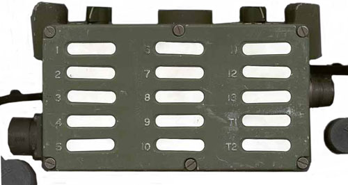
TM 11-5820-890-30-5 Chapter 18 has some operation information on the Fill Device Select rotary switch:
"A"
means fill or load All channels
"1
through 13 are individual channel numbers holds hop sets
T1
through T3 = Transmission Security Key (TSK) controls the order of
the
hop set.
The button in the center is to INITIATE a transfer into the fill device. Either from a key generator or from another fill device.Note: There is no provision for holding Transmission Encryption Keys (TEK) since they would be used with the KY-57 and are handled separately.
Typically the initiate fill command is given from the device receiving the key.
KOI-18
The early KOI-18 fill device was a paper tape reader where the tape is manually pulled through the reader. It probably uses a standard 8 level teletype tape. As each character is being punched into the tape a sprocket hole is also punched. The reader probably uses light and photocells to detect if a hole is in each position and uses the sprocket holes as a clock signal. The neat thing about this reader is that is can handle any byte oriented data format of any length that's practical to hand pull.Since the bytes are parallel and the data needs to be in serial format there needs to be a simple parallel to serial converter. This may have been done using a parallel to serial IC and a clock running at a speed fast enough so that the conversion is done before the next parallel byte is read. In case the operator gets overzealous and pulls the tape too fast there needs to be a way to know that the data was garbled. This may have been done using odd byte parity. Note that odd parity shows an error if all the data bits are zero and shows an error if all the data bits are one. So a "rub out" or "null" character (all holes) would create an error, meaning that rub outs are probably not allowed on key tapes.
KYK-13, MX-10579 and MX-18290
These are all very similar in appearance and have the same controls. The KYK-13 may only have 6 storage locations whereas the other two have 15 stoarge locations.The KYK-13 sends the data in the selected storage location when it receives a transfer request. The target device that initiated the transfer request will negate the request when it detects a clock signal from the KYK-13.
The logic volatges used may be 0 and 6.5V but the thresholds should accept rail to rail (CMOS) 0 to 5 Volt signals.
CV-4228 PC to SINCGARS Fill Cable
J1 is a 6 pin U-229 type connector and might as well have been a 5 pin U-229 since the center "F" pin has no electrical connection.
P1 is a 6 pin connector that will mate with J1 on another fill divice so two fill devices can bo connected toghther without using a cable.
pin P1 J1 Function Handset function A J2-18 J2-18 Ground ground B nc nc na Earphone
(audio from radio)C J2-1 J2-1 Fill Request from radio PTT
(gnd to talk)D J2-6 J2-6 Fill Data to the radio Mike
(audio to radio)E J2-16 J2-16 Variable rate clock to radio na F nc nc na na The definations of pins C and D may give a clue as to the functions of the same pins on the KYV-2() Secure Voice Module Key Load Connector. But the SVM uses pin A to receive DC power from the key loader so that it can be programmed when not attached to a radio. The SVM uses pin E to monitor the Hold Up Battery and pin F as common ground. So it looks like the 18290 can not load the key into the SVM unless a special cable was used.
Note that none of the P1 or J1 pins are connected to the case of the MX-18290, it's case is only connected to the shells of the connectors. All electrical circuits are isolated from the case which only acts as a shield.
Stimulus Test
With pin A as ground a stiulus (3 AA cells in series with a 1 k Ohm resistor) is applied to each pin. The voltage on the remaining pins is measured with a 100 k Ohm resistor to 3 AA cells, about 4.7 Volts.
7 Feb 2006 - need to repeat this chart using negative polarity test voltage.
Pulled up in this chart means to a positive voltage & pulled down means to grund.
* = same as no stimulus
VA
VC
VD
VE
no stimulus
0
0.58
0.58
0.58
C pulled up
*
2.7
*
*
D pulled up
*
*
2.7
*
E pulled up
*
*
*
2.6
C pulled down *
0
*
*
D pulled down *
*
0
*
E pulled down *
*
*
0
C pulled Negative
D pulled Negative
E pulled Negative
BA-5372/U is the standard 6 Volt Hold Up Battery for the SINCGARS radios, but in this case it is used both for hold up (switch OFF) and to power the circuitry (switch ON). The batttery compartment has "+" and "-" signs cast into the body of the MSX-18290 and there is a notch for the non standard negative tip that will not allow the battery to go in backwards.
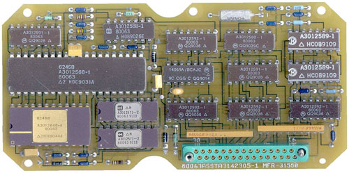
Left to right, top to bottom.
IC #
Manufacturer # of pins
+
(- is #/2)Govt # other #1 Date Code 1 74LS174
Mot 16 A3012591-1 80063 QQ9028 2 4011B Harris 16 A3012588-1 80063 HOB9026E 3 74LS367
Mot 14 A3012592-1 80063 QQ9039C 4 4011B
Mot 14 A3012580-1 80063 QQ9039C 5 40109B
Harris 16 A3012589-1 HCOB9109 6 1802 Harris 40 A3012568-1 80063 HOC9031A 7 4069
Mot 14 14069A/BCAJC QQ9014 8 74LS174 Mot 16 A3012591-1 80063 QQ9028 9 40109B Harris 16 A3012589-1 HCOB9109 10 2732 ROM Harris 24 A3012646-4 80063 2HOB9044A 11 1kx4 RAM
Harris 18 A3012571-2 80063 9113 12 74LS367 Mot 16 A3012592-1 80063 QQ9036 13 74LS367 Mot 16 A3012592-1 80063 QQ9036 14 74LS367 Mot 16 A3012592-1 80063 QQ9036 15 1kx4 RAM Harris 18 A3012571-2 80063 9113 Note that the following are the same part numbers (A3012591-1):
The two 1kx4 RAM chips make a 1kx8 or 1k byte RAM. This is 8,192 bits.
1, 8
3, 12, 13, 14 .
5, 9
11, 15 - most likley the static CMOS ram chips.
Possible storage (19 April 2004)
If the the radio covers 30 to 88 MHz with 25 kHz channel spacing there are 2320 channels available. At one bit per channel you would need 290 bytes to store that data. If 13 hop sets were stored you would need 3,770 bytes (30,160 bits), more that the RAM chips can hold (8192 bits).
The 3 TSKs are not compatible with the TEK and so might be 64 bytes long using up 128 bytes (including parity and check sums), and would leave 896 bytes for the 13 hop sets. 896 / 13 = 68.92 bytes rounded down to 64 bytes per hop set. This implies that each individual frequency is not selectable, but rather they are grouped maybe 4 or 5 adjacent frequencies (i.e. the 30 to 88 Mhz band is broken down into segments 100 kHz or 135 kHz wide and each of these segments is either in or not in the hop set. If it was 150 kHz (5 channels) then instead of needing 290 bytes for each hop set it would only take 58 bytes per hop set..
Channel & ID Information (3 July 2005)
When a Lockout set is loaded into the radio an ID appears in the display. It has the from LF234. Where the "L" is for frequency Lockout and the letter (F) and 3 digits are the ID. In a similar manner when a hop set is loaded it's ID appears in the display, but with F for FH sets and L for Lockout sets. The ID ends with 3 digits (000 to 999) and these are the different start times so multiple nets can operate using the same TSK and hop/lockout sets. The ID information needs to be stored in a header that's part of the frequency fill. A hop set and a lockout set are loaded in exactly the same way, so the header and/or data format needs to tell the radio if it's a FH set or a Lockout set. On most radios when in FH-Master mode the NCS can change two digits of the net ID.
28 March 2006 - So the header must contain at least:
which adds up to 16 bits or 2 bytes.
- one letter (5 bits) and
- a number between 0 and 999 (which takes at lest 10 bits) and
- 1 bit for Lock or Hop
The more key space that's taken up with the overhead (header, parity bits and CRC) the less space is left for the actual key. To maximize the strength of the key you want as many key bits as possible and as few overhead bits as you can get away with. In the case of DES the published key length is 64 bits (8 bytes) but the actual bits used for the key are only 56 bits, one byte goes to overhead (such as a parity bit on each byte).
Parity Note
Using a parity bit is one way to confirm that the data is what it's supposed to be. For example in RS-232 serial communications each byte can have either: Even, Odd or No parity, the most common being No parity. If a device holding a key looses power and then powers back up with a blank memory and an even parity check is made on all zero data the parity check would pass but if an odd parity check is made on all zero data it fails. So of the three possible parity checks (No, Odd or Even) only an odd parity check detects all zero data.
It may be that some keys use parity at the byte (8 bit) or word (16 bit) level and other keys may use a Cyclic Redundancy Check (CRC) or Check Sum on the whole key or both.
Note that the parity bit is an additional bit so when it's used a single character is sent as:
But the KOI-18 uses 8 level paper tape and so any parity needs to be made part of the 8 data bits. But that could be done for either a single byte or for a group of bytes where a group might be two bytes (a word) or more bytes.
- Start bit
- 8 data bits
- Parity bit
- Stop bit
Protocol
The MX-18290 does not use parity, but instead uses a CRC in a way similar to DES. Each block of eight bytes has the last byte as the CRC. The MX-18290 uses a CRC method that's different from the published methods. On some (all?) CRC calculators if you feed in the data bytes and append an all zero byte the output number is the CRC. When that CRC is appended to the data and fed into the CRC calculator the output is zero. Sort of like an exclusive OR gate.
A Thought
If after calculating the CRC for a block a constant is added (MOD 8 bits) then when checking the CRC if that number is subtracted first and then the CRC calculated the result should be zero. This would allow coding the protocol without increasing the size of the key. For example a device like the MX-18290 will accept keys for SINGARS transmission parameters and the green self test LED will confirm they are good keys. But if a key for something else is loaded the MX-18290 will not show a valid SINGARS key. Yet they both may use the same eight byte block with CRC data structure.
TM 11-5820-890-30-5 (ETM 070228.pdf) Chapter 2 and Chapter 18 have some information. Fig 2-11 Fill Circuit Diagram shows a connection to the RT-1439 SINCGARS radio. Note the RT-1439 was a non-ICOM (i.e. it did not have embedded voice security, only anti jam frequency hopping.)."A" means fill All channels
Rotary switch:
The button in the center is to INITIATE:OFF - ON - ZA the ZA means Zero All parameters (zeroize).
- a test of a single channel by setting the rotary switch to a channel, press INITIATE and the LED should blink green indicating a loaded channel
- a zeroize operation, set power switch to ZA, rotary switch to A, press INITIATE, and the LED will ? indicating all channels have been cleared
- a request for an external device to load the selected key slot.
The cable used with the Fill Device has 6 wires connected 1 - 1.
ITT has informed me that the protocol used on this device is not in the public domain.
OFF - ON - ZA
This is a SP3T switch.
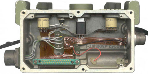
OFF - In this position the 6.5 Volt Batt + goes to J1-15 and through (R1 then D3 and R2 in parallel) then R3 to IC11 & IC15 pin 8. I think this is a keep alive power pin on identical static RAM chips that hold the key data. These chips are also powered by VCC (node 18B).
ON - All these chips turn off to save power. In this position the Batt + goes to J1-18 then has three branches:U6 appears to be a microcomputer not a microcontroller. That is to say that it has address and data lines and there are AC signals on most of the chips. Without a logic analyzer it's hard ot say what's going on.
- through D1 with electrolytic C1 to ground then IC 2, 3, 6, 11 and 15 These chips have some keep alive time due to C1. This would allow the microcontroller some time to go into the standby state. Maybe IC6 is the 40 pin microcontroller,
- through D2 with no caps to IC 1, 4, 7, 8, 9, 10, 12, 13, 14. These may be related to doing I/O with the switches & LED on the box.
- direct to IC5 no diodes or caps. This is the IC that is connected to P1 J1 pins D & E.
Fig 2-11 (above) shows:
- pin C as Fill Request from radio
- pin D as Fill Data to the radio
- pin E as Variable rate clock to radio
U10 may be the the program code and U11 & U15 hold the key data. U7 is a 14069A/BCAJC which is a hex inverter 1>2, 3>4, 5>6, 9>8, 11>10, 13>12. The MC14069UB hex inverter is constructed with MOS P–channel and N–channel enhancement mode devices in a single monolithic structure. These inverters find primary use where low power dissipation and/or high noise immunity is desired. Each of the six inverters is a single stage to minimize propagation delays. Probably all the ICs are CMOS type for low power dissipation. The 6.5 Volt supply draws about 600 uA in ON mode and 82 uA in OFF mode.
With power ON the following lines have active AC signals:
U1: 1, 3, 4, 6, 9, 11, 12, 13, 14
U2: 4, 5, 6, 10
U3: 4, 5, 6, 7, 9, 10, 11, 14
U4: 1, 4, 5, 6, 11, 12, 13
U5: no activity (probably only goes active during serial coms up/dn loading data)
U6: 1, 6, 7, [Data bus: 8, 9, 10, 11, 12, 13, 14, 15], [address bus: 25, 26, 28, 29, 30, 31, 33, 34], 35, 39
U7: 3, 4, 5, 6
U8: 3, 4, 6, 11, 13, 14
U9: 5, 7, 9, 11, 13, 14
U10: 2, 3, 4, 5, 6, 7, 8, 9, 10, 11, 13, 14, 15, 16, 20
U11: 1, 2, 3, 4, 5, 6, 7, 8, 10, 11, 12, 13, 14
U12 3, 5, 7, 9
U13: 3, 5, 78, 9, 11, 13
U14: 3, 5, 7, 9, 11, 13J2 (board to box connector):
15: OFF Battery
18: ON Battery
14: ZA Battery
27: Ground to turn on LED
22: pin 18 through a resistor to LED
2: S3-1
17: S3-2
3: S3-3
19: S3-4
5: S3-5
21: S3-6
23: S3-7
25: S3-8
24: S3-9
7: S3-10
20: S3-11
4: S3-12
11: S3-13
26: S3-14 (T1)
12: S3-15 (T2)
28: S3-16 (A)
18: P1 & J1 A
1: P1 & J1 C
6: P1 & J1 D
16: P1 & J1 E
ITT INDUSTRIES INC
ITT AEROSPACE/COMMUNICATIONS DIV
1919 W COOK RD
PO Box 3700
FORT WAYNE, IN 46801-3700CAGE CODE: 31550
Status: A - ActiveDUNS Number: 005420245
Voice Telephone: 219-451-5640
FAX Telephone: 219-451-5066County: ALLEN
Date CAGE Code Established: 11/04/1974
Last Updated: 06/25/1998
ADVANCE CIRCUITS INC - - - - - - - - - - made the PCB
15102 MINNETONKA INDUSTRIAL RD
HOPKINS, MN 55343
CAGE CODE: 32665
Status: A - Active
Voice Telephone: 612-935-3311
County: HENNEPIN
Date CAGE Code Established: 11/04/1974
Advance Circuits
5929 Baker Road
Suite 470
Minnetonka, MN 55345
Phone: (612) 988-8700
Fax: (612) 988-8727More than 150,000 SINCGARS have been built for the U.S. Army and Marines and national defense forces in Asia, the Middle East and Europe. The SINCGARS Advanced Tactical Communications System (ATCS), and the Advanced Lightweight SINCGARS Improvement Program (ASIP), are the latest generation of tactical communication systems.
New products such as the Mercury Near Term Digital Radio (NTDR) for high capacity wireless networking; remote meteorological sensors for earth monitoring programs; Dragonfly, a network protection device; and Speakerkey, a security system that uses voice analysis, are just a few of the products that shine in the bright future of ITT A/CD.
FM 24-19 - Communications Security Equipment - although not this equipment, some very similar boxesBack to Brooke's Crypto, PRC-68, Military Audio, Squad Radio, Military Information, Home page
RCA CDP1802 COSMAC microprocessor
This is the [an error occurred while processing this directive] time this page has been accessed since since 7 July 2001.