Noise in electronics (Wiki) amounts to an electrical signal that's random in nature. Thermal Noise (Wiki) depends on the temperature, bandwidth and resistance of a circuit. Some noise generators work based on these parameters (see: Aerospace Noise Generator). Other hardware noise generators use diodes in avalanche mode to generate noise. Radioactive sources can also be used. In computer science & cryptography there's a concept of a pseudorandom number generator (Wiki: PRNG) but they are deterministic. A hardware random number generator (Wiki) does make truly random numbers if it's done correctly.
This noise generator is intended for testing radio equipment in the 100 Hz to 1,500 MHz frequency range. It includes a number of step attenuators to allow changing the noise level.
This is a rack mount box that's 3 units (5.25") high and 13" deep.
It's designed to be powered by 1115 VAC, i.e. standard U.S. 60 Hz line power.
The CPU board has an IEEE-488 connector to allow remote control of all functions, but it also has front panel controls and indicators so can be operated without using the remote control feature (If you have an instruction manual which so far I don't).
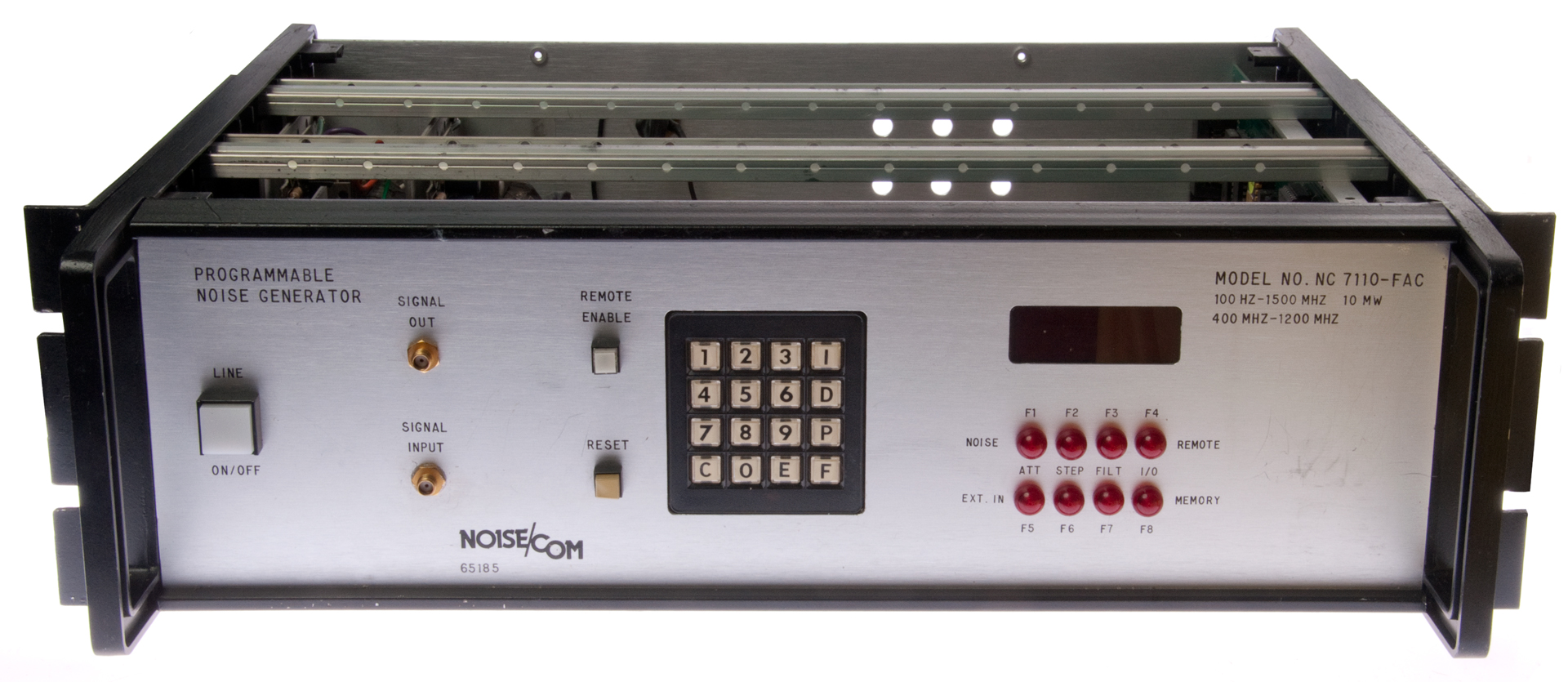
The upper right of the front panel (Fig 1 below) is marked:
Model No. 7110-FAC
100 Hz - 1500 MHz 10 mW
400 MHz - 1200 MHz
The difference in these frequency ranges may relate to the noise bandwidth and power (100 Hz - 1500 MHz 10 mW) and the Signal Input bandwidth (400 MHz - 1200 MHz).
Controls & Indicators
Push-On/Push-Off Power Switch
Signal Out SMAf (top)
Signal In SMAf (bottom)
Remote Enable push button (top)
Reset push button (bottom)
4x4 Keypad
It's not known what the letters are for or how the pad is used.
1
2
3
I
4
5
6
D
7
8
9
P
C
0
E
F
I'd guess you should be able to setup both the Signal In path and the noise path.
LED display (has not yet turned on so no info.
Indicator Lights (8 each = O below)
F1
F2
F3
F4
Noise
O
O
O
O
Remote
Att
Step
Filt
I/O
Est In
O
O
O
O
Memory
F5
F6
F7
F8
The rear panel (Fig 3 below) has the IEC AC line input jack, a fuse and an IEEE-488 remote control connector.
Photos
Fig 1 Front Panel (top removed)
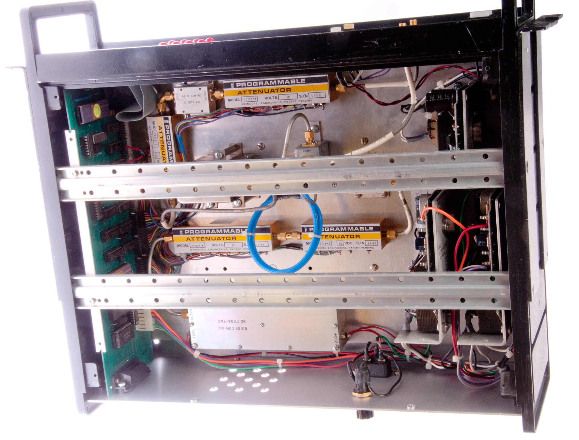
Fig 2 Inside
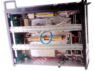
Fig 3 Back & Top
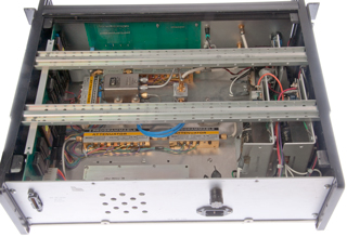
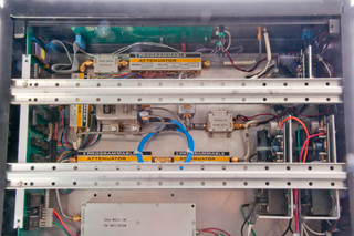
Fig 4 Inside
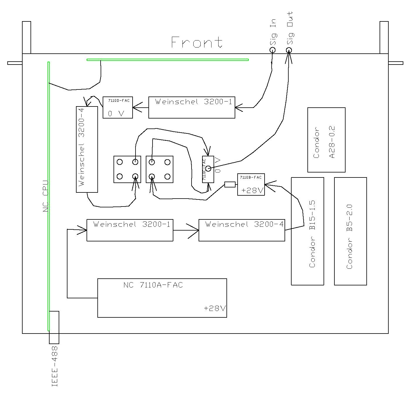
Block Diagram
Compare to Figures 2, 3 & 4 above.
There are two K&L transfer switches and each has two terminations. So I'm guessing that the Signal Output can be terminated with no signal, a version of just the Input Signal with programmable attenuation, noise with variable power level but with none of the input signal or some combination of the Input Signal and the Noise with the levels of the input and noise adjustable.
The two square boxes each with 4 ports are
K&L TS-12-F-Q transfer relays (12v).
The ports shown with no connection are terminated.
Dead On Arrival
The eBay ad said For parts or not working so this was expected.
The first thing I did when received was to take photos and generate a block diagram, see above for both of these.
The next step was to power it up and measure the power supply voltages.
Note: for the Condor power supplies, the first letter is the case size, the number is the nominal voltage and the number after the dash is the max current in amps.
Power Supply
Expected
Voltage
Measured
Voltage
% of Expected
A28-0.2
28
16
57
B15-1.5
15
9
60
B5-2.0
5
4
80
Since the 28 VDC supply appears to be the most overloaded, I'm going to disconnect it's output and see what voltages each supply shows.
Disconnecting the 28 VDC output gives 19 Volts, not 28. The other supplies are also reading low.
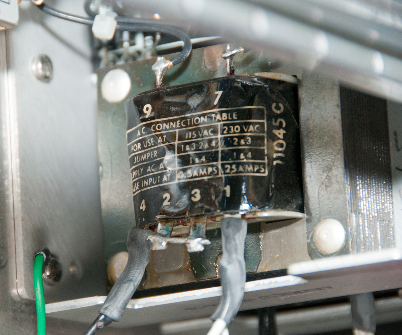
The transformers on each power supply have a table showing the connections for 115 VAC input and 230 VAC input and they are wired for 230 VAC, not 115 VAC.
So the problem and the fix are clear. It's difficult to work on the power supplies because the cross bars on top are in the way and it's not clear how to remove them, so the plan will be to remove the bottom cover and dismount the power supplies to rewire.
Note you can see in the photos below that there were white and black wires that have been cut off. They were the jumpers for the 115 VAC connection.
115 VAC
230 VAC
Jumper
1&3
2&4
2&3
AC Line
1
4
1
4
Fuse
0.5A
0.25A
Fig 5 Condor B15-1.5 (230 VAC wiring)
Fig 6 Condor A28-0.2 (230 VAC wiring)
19" Rack systems
Aerospace Noise Generator
computers
cryptography
Crypto Machines
Radiation detectors