There are now many Digital Radio Modes that allow testing antennas-propagation, see for example WSPR. using a 200 mW signal and a message frame time just under 2 minutes a 30 dB improvement in s/n can be obtained.
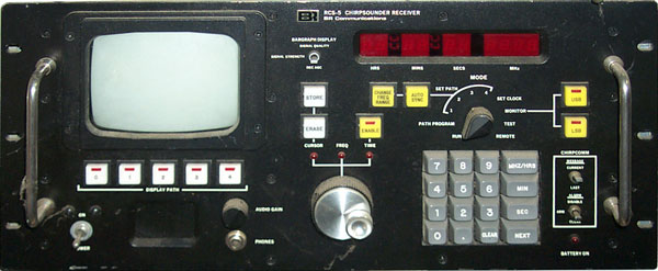
In the beginning the only way for a hobbyist to receive chirps was by using their ears and a short wave receiver tuned to a fixed frequency or manually tuning the receiver or use a commercial chirp receiver like the RCS-5().
Next came the Motorola 56000 DSP Evaluation kit based chirp sounder receiving method. With this method the DSP time stamps, using a GPS locked 1 PPS, each sounder as it passes through a fixed frequency. This is a great method of finding sounders and of determining where they are by triangulation.
Next came the PC sound card version of the DSP method called Chirp View. by Andrew Senior. In this method the 1 PPS from a GPS goes into one of the audio channels of the sound card and the other channel gets the chirp from a fixed tuned receiver. Generates a log that's in the same format as the 56000 DSP method.
Currently (Jan 2004) there is work on a new method based on the Software Defined Radio which will use a swept Local Oscillator and produce an ionogram, just like the RCS-5. There is a possibility that this type of chirp receiver can also decode the chirpcom message that contains up to 40 characters repeated 63 times in a 2 to 30 MHz sweep.
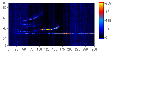
20 Oct 2004 - G4ZFQ Combining ChirpView & HRD to get ionogram.
2017 Aug 4 - gcs GNU Chirp Sounder - uses a pair of loop antennas and a pair of SDR radios.
Mailing List
Chirps - Mostly log files from either the 56000 based or PC based single frequency methods and info on new sounders. Includes both BR and other sounders. Some infoo n the SDR based method.
To subscribe send a request to mailman-owner<at>aintel.bi.ehu.es
Yahoo Group
Chirpsounders Mostly propagation info and BR sounder status.
Antenna Pattern
When BR Communications (before they were bought by TCI) first worked on chirp equipment they used the HP 5110 synthesizer. This does NOT have any phase lock loops, it works with arithmitic (add, multiply, subtract) and is phase coherent through frequency changes that happen a in a few microseconds. The remote programming is with a wire for each button on the front panel. See photo of my unit (two upper instruments). I first learned about these signals from the September '93 issue of Popular Communications article "Monitoring the World's ionosounds" by Andrew W. Clegg.
RCS-5A/B Data
sheet at BR communications - Fixed 6 Jan 2001
FM
24-18 - Appendix
B Ionospheric Sounder AN/TRQ-35(V) -
FM
24-24 - AN/TRQ
35(V) Tactical Frequency Sounding System -
RCS-4B (R-2081/TRQ-35(V)) NSN 5820-01-005-4247 - TM
11-5820-917-13 (368 pg pdf file REQUIRES 128 bit Netscape,
no others)
Example 1:Now suppose that there are two different paths from transmitter to receiver, one a surface wave and another that is a single hop to one of the ionosphere layers. The receiver will hear two simultaneous audio tones that will be fixed in frequency if both paths are of constant length. In the real world the path(s) are changing constantly as a function of frequency then the result of a chirp sounder sweep is a plot of the layers -vs.- frequency and also a plot of received signal strength-vs.- the same frequency x-axis.
a 3,000 km path length
will cause a time delay of (path length km) / (speed of light) = 3,000 km / 300,000 km/sec = 0.01 sec = 10 mS
the audio tone frequency that will be caused by the difference between the transmitter carrier and the receiver LO is: 0.01 S * 100 kHz/S = 1,000 Hz
This tone will be the same audio frequency for all received RF frequencies if the path length is constant.
That is because both the transmitter and receiver oscillators are sweeping at the same rate.
The chirp sounder receiver uses an audio spectrum analyzer to look at what frequencies are present. Each frequency represents a path delay and a different type of propagation.
A Scale drawing showing
propagation. This gives some idea of the minimum and maximum
single hop distances.
In Feb. 2000 I installed the B&W (BWD 1.8 - 30).
The high end is up about 85' and the low end about 40' and at
least 25 feet from the trees.
Listening to WWV I can see a 10 dB increase in signal
strength. In some cases this makes the difference between
hearing a station and not hearing that station!
Using this antenna with the NRD-545 and going through the Passport
to World Radio book, where I mark stations that I can hear, I
marked 2 or 3 times as many stations as I had using the
McKay-Dymec DA100 active whip. DA-100 Board Layout & Circuit Diagram.
With the RCS-5A the B&W antenna is a great improvement!
Wide Band Folded Dipole
I was using an old McKay-Dymec DA100 active whip. I was hearing what BR/TCI hears with their massive 2 - 30 MHz log periodic.
The B&W Broadband Folded Dipole Antennas (ASW-90) U.S. Patent 4423423 are a better choice. I saw one today at the Santa Rosa National Guard on highway 101. This antenna is designed to have continuous coverage for both transmit and receive, although the transmit performance is poor on the lower frequencies.
T2FD - is another name for the B&W 2-30 antenna.
T2FD Antenna - Terminated, Tilted, Folded Dipole by David Gordon KB4LCI - T2FD dimensions - says good for a 6 to 1 bandwidth
Modeling the T2FD - by L. B. Cebik, W4RNL - in an amateur TRANSMITTING application
How To Build the TTFD-2 - Diagram - at Radio Habana Cuba
Codan Pty Ltd - Code 411 Terminated Folded Dipole -
KIWA - Shortwave PreAmp - provision for use with T2FD
June 1949 issue of QST, May 1984 73 Magazine, 1989 WRTH, "Practical Antenna Handbook, 2nd Ed.", by Joseph J. Carr
Nordic Shortwave Center - Comments under "Special" - T2FD - The Forgotten Antenna - T2FD design -T2FD vs Other antennas - excellent receiving antenna -
Spi-Ro Manufacturing - all band - amateur 70' overall (uses loading coils) or 135' dipole no coils
Loos & Co - Tension Gauges -
Antenna Products Corp HT20-B - this was mentioned on a newsgroup
T2FD -- The Forgotten Antenna
Bushcom - BBA-100 - looks interesting, but pricey
Array Solutions USA disty for the BBA-100 with data on it.
Loop
K9AY Loop - QST 9/97 pg 43-46 & QST 5/98 pg. 73
A Compact Directional Receiving Antenna by K9AY -
Al - K4GLU - comments and improvements -
EWE vs K9AY LOOP -
TopBand: K9AY 's Loop & ICE - Would the ICE Beverage Matching Assy, Model 181A (DC Passive) work with the circuit used by K9AY for his switchable EWE array?
Industrial Communication Engineers Inc. (ICE) - model 180 matching transformer (web page not complete)- Nordic Review -
Wellbrook Communications - makes the K9AY loop - BDXC Review of Wellbrook Communications K9AY Antenna System - also has conventional ALA 1530 loop. These may provide a way to get DF bearings on chirp transmissions.
Nordic Comments QST 9/95 -
ARRL - Receiving Wire Antennas -Wide Band Vertical
Sommer Antennas
model T-25 - (1.5) 3.5 - 60 MHz - Principles of operation - $260
model T-50 - 1.0 - >30 MHz - Principles of operation - $540NVIS
Near Vertical Incident Scattering Antenna -
TCI/BR - AS-2259 -
WB5UDE - NVIS: Near Vertical Incidence Skywave -
AN/TRC-510(V) - with photo of AS-2259/GR NVIS antenna & fast tune ant. tuner
Fort Gordon - Single Channel Radio Operator/Maintainer - I02-LP2: Construct NVIS Antenna AS-2259/GR. (2 Hrs) - FM24-1 Appendix M Near-Vertical ncidence Sky-Wave Propagation Concept -
Book "Near Vertical Incidence Skywave Communications--Theory, Techniques and Validation" by David M. Fiedler and Edward J. Farmer. It's published by Worldradio books, Bos 189490 Sacramento, CA 95818
Tactical Link Systems - Mobile NVIS - details on a mobile NVIS antenna system
EYRING CORPORATION - ELPA Model 302 A -5.3 Lbs, 2 to 65 MHz.TCI - 545
Both NVIS and low angle (switchable) 40' mast - very interesting - is 4 seperate wires wound around the guys.
This antenna can be fed for either vertical or HORIZONTAL polarization! When in horizontal mode it is more like a wide band dipole.My Sketch of a possible 545 antenna using logrithmic spacing along guy, 16 wires per side, k=1.1 and a=16"
TCI_545.dwf you need WHIP! or Volo to view this drawing.Antenna Transformers
SWL Longwire Impedance Matching by John Doty -
Boston Area DXers (BADX) - Low Noise Antenna Connection -
ICE Matching Transformer - ICE -Active
dressler - various models 40 kHz - 2,000 MHz
Chirp is not a magic mode and for some paths you can only hear anything at certain times of the day/night. The station in Reykjavik can not be heard around 00:00 UTC but can be heard around 17:00 UTC.
I have found that if you set the RCS-5 in manual mode, and put it into autosync with a new start time ending with .0000 seconds. After a day or so you may find it in normal sweep mode and the start time will not have changed. This indicates that autosync was fooled by some signal.
There are two serial ports in the J4 connector. RS-422 or RS-423 is supported so that a number of receivers can be controlled from a single computer and to increase the distance between the computer and the receivers. These ports can be wired to communicate using RS-232.Drawing for the J4 cable with both Port 1 and Port 2) RCS-RS232.dwf - (Get Whip!, Volo, etc ). This cable has been used for Port 1 and 2, it works. I made up the printer cable but it did not work with my HP LaserJet 4 printer. The manual mentiones "ESC L" command sequence for double density (72 x 120 DPI) used by Epson and Okidata printers. I think this is a format that predates Postscript and HP PCL.Note that the check sum on transmitted data does NOT include the single command letter!
Port 1
Port 1 is a bi-directional port for all commands and responses except the raw data which is sent over the one way port 2. To use the port 1 commands and data outputs:Now it will process commands on port 1. The "Read Chirp Data" command returns a graphic data set that matches the CRT on the RCS-5A, that is to say it is 1 bit per pixel data. The AGC, Signal Strength and Path Quality data is also returned from this command.
- the "Mode" switch the the RCS-5 front panel must be in the "remote" position.
- Then one of the "greet" commands must be sent to the RCS-5A.
Port 2
Port 2 is constantly outputting data and the "mode" switch has no effect on this. There are 3 different data blocks:
- 2 byte status block sent between sweeps or Autosync attempts
- 86 byte block sent at the end of a sweep with signal strength, AGC, ID information, etc.
- 107 byte block during a sweep with each byte cntaining the signal amplitude for each pixel and some other data. This allows an intensity graph to be plotted for the sweep. Example intensity plot: Utah 10/19/99 00:05:45 UTC Note that on 18 Oct. 1999 there was a large solar storm which reached Earth starting 18 Oct. You can see solid sporatic-E propagation all the way to 30 MHz!
Path Programmer
I think of this as "time slot" programmer. There are 12 lines (one for each 5 minute time slot) and you can assign one of the 4 paths to a time slot or if zero is set then the time slot is not used. Remember that the paths are defined by the start time ( zero to 4:59 minutes) and upper frequency limit (either 16 or 30 MHz). When the mode switch is in ANY position other than "monitor" the RCS-5 will be looking for the start time for the current time slot and will start a sweep. When the computer program finishes, if there are valid paths and slot assignments the receiver will continue to sweep.Path Overlap
For example suppose that paths 1,2 and 3 are set for start times of 0:32, 0:35 and 0:45 and "auto-sync" is enabled for all these because we are just getting started. Also suppose that the time slots for these are:
slot path (minutes past hour) Start time +4:40 = end time + pause = next start time
0 1 0 0:32 5:12 0:23
1 2 5 5:35 10:15 0:30
2 3 10 10:45 15:25 0:07
3 1 15
4 2 20
5 3 25
6 1 30
7 2 35
8 3 40
9 1 45
10 2 50
11 3 55Now the receiver will try to sync on the first path starting at 32 seconds past the hour. That sweep will end 4:40 (all sweeps take 4 min and 40 seconds) later at 5:12 past the hour. There will be a 23 second pause while the receiver waits until 5:35 for the second path to start. The second path will end at 10:15 past the hour and will pause for 30 seconds waiting for the third path to start at 10:45 past the hour. It will finish at 15:25 past the hour. The first path will start at 15:32 so there will be a 7 second pause. In this example there is not any problem because there always is a pause between paths.
If the third path in the above example is now changed to start at 0:55 there will be a problem because the third path will now start at 10:55 and end at 15:35 or 2 seconds AFTER the first path was supposed to start. If path 3 is in auto-sync mode then path 1 will NOT start, path 3 will finish and there will be a pause of about 5 minutes then path 2 will start. So the sequence will be path 2, path 3, long pause, path 2, etc.
It is important how the start times and time slots are assigned. When searching the next start time can be 1 or two seconds later than the prior path thus not wasting time pausing, making the search more time efficient.
Sync Range
The RCS-5A will sync at least over a 1 second range but not 2 seconds. This means that there can not be two separate transmitting stations with start times 1 second apart and have the same time slot assignment. If you look at a Start-Time List you will see that there must be at least a 2 second separation between start times. In the log above there are a couple of cases where I am showing start times less then 2 seconds apart and the same time slot. These must be some kind of error in the scan program and will be resolved.LabVIEW Code
For those who would like to use a computer to capture data from an RCS-5 I am posting some 32 bit Windows LabVIEW 5.1 software. This is NOT a finished product, but does work. I use this software while manually setting the receiver for the stations that I want to capture. The output is a color intensity graph, even though the screen on the RCS-5A is black and white.The P2-Raw_data.vi needs to be loaded and running in the background. It can be minimized down to the task bar. It listens to the RCS-5 port 2 data stream that is coming from the receiver in all positions of the "Mode" control except for "monitor" during each sweep. It is separating the data stream into three different packet types (2, 86 and 107 bytes long) and sending them to a global variable that can be read by other programs. This VI calls Read_N.vi that gets the data from the LabVIEW serial port buffer. It also calls P2_Status.vi that decodes the Port 2 status byte.
Int_Gph4.vi is the program that I have open and manually start about 1 second after a sweep starts that has already been synchronized, or if the receiver is in auto-sync mode and I hear it sync I start the program. In a future improved version this VI could be called by the computer for each receiver sweep and the result automatically saved to disk. I have not yet decided on what data to save to disk and in what format. This VI calls Chirp_Gph.vi that breaks apart the 107 byte packet into data ready to graph. When the sweep stops I currently just <alt><print screen> and paste into Windows Paint then save as a jpeg image. There is a stock vi that will convert a graph into a jpeg file, but I have not been able to get it to work properly. If anyone gets it working, let me know.
The first 2 characters of the message are reserved for the ID of the transmitting station, but can be anything.
There is also provision for either a general alarm or a selective
call alarm where the 2 character receiver ID must match the Selcal
characters. Inchon is the only station that I know of that is
sending a general alarm, I have not tried to search for a
selective alarm.
See patent 4244053 below. The Air
Force liked it for long range bomber coms.
Using this method I found the BR Utah station in the first line of the logging table above.
Example 2:Power Supply Problem - was fixed by - as far as I can remember - an office of Reasonat Power Technology in Milpitas, California. But their web page only shows South Dakota. The interactions between the different switching mode supplies makes troubleshooting very difficult.
tuned to 9.000 MHz
hear chirp at 07:09 (mm:ss) local time
know the sweep rate is 50 kHz/sec. = 20 sec / MHz
delta frequency since start is 9 MHz - 2 MHz = 7 MHz
time since start was 7E6 MHz / 50E3 kHz/sec = 140 seconds prior to hearing the chirp at 9 MHz
7:09 = 6:69 = 5:129 = 4:189
4:189 - 140 = 4:49G3PLX Chirp Project - http://www.qsl.net/zl1bpu/chirp/chirps.html -
Note that "chrip time" in the G3PLX system is at zero frequency. This makes the math much easier, but you need to add 20 seconds for BR start times.
This is a spectrum monitor based on the RCS-5 Receiver Chirp Sounder. It covers 2 to 30 MHz in 3 kHz cells with a sweep taking about 12 seconds. Unlike a spectrum analyzer the RSS-5 stores channel use history for 30 minutes. You can have it just scan channels (frequiencies) that you are interested in. The purpose is to see if a channel is being used. The RCS-5 can show at the top of the CRT the receiver AGC, signal strength or signal quality. I think that these are the basis of the RSS-5. If you have a chirp sounder receiver that will tell you what frequencies will propagate and a RSS-5 to tell you what channels are not being used, then you can make a selection of the frequency that has the best propagation and the lowest usage giving you the highest probablity of making contact.
Photo1 , Photo 2, Screen Shot

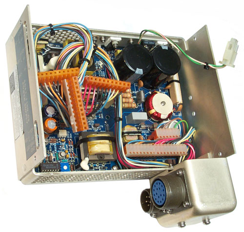 |
F1
is just below the toroid and connector at the right center. |
 |
F2 is in upper right
corner. |
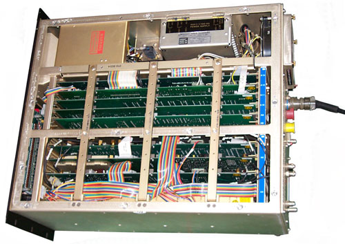
TCI/BR RCS-5B Chirp Receiver Power Supply Troubleshooting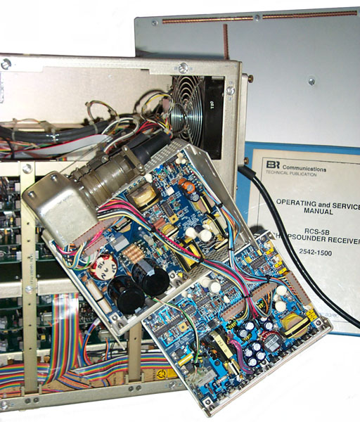 The A18 power supply can be
removed from the receiver (4 screws on side panel) and
then opened up (4 screws on PS) and then folded open to
allow troubleshooting. The top has the input and
output connectors and all of the HV related
circuitry. There is a 2 wire (wh/red, grn/brn)
cable that feeds +300 and 300R to the +24 Volt supply in
the bottom. The key test points are 300, 300R,
U17-7 in the top part. The problem seems to be in
the area of U17 (CS2842A) and Q42 (BUZ50B). The
breaker trip signal is in the large J2 mil connector and
the line inputs are in the smaller J1 connector so it
may be a troubleshooting technique to disconnect J2 for
troubleshooting. I'm trying to confirm that before
trying it.
The +24 V supply feeds the +5 and +12 VDC supplies all of which are in the bottom part. |
|
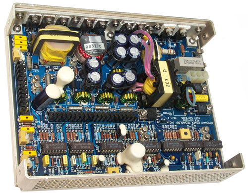
TCI/BR
RCS-5B
Power Supply Top HV PCB The top PCB removed from it's metal housing to get access to the back side. |
|
| Test Point |
Name |
Voltage to gnd (J6) No Load |
Adj
R111 was: 6.0 V now: 6.2 V |
Voltage to gnd (J6) Loaded |
| ? | Pwr Det | +3.0 | +5.1 |
|
| J4 | -12 |
-12.17 |
-6.65 |
|
| J3 |
+24 |
+23.7 |
+21.86 |
|
| J2 |
+12 |
+12.17 |
+12.13 |
|
| J1 |
+5 |
+5.21 |
+5.1 |
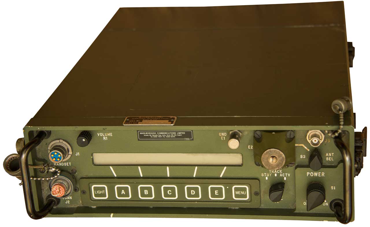
Many years ago I thought the manpack transceiver was called the BR 4280. I may be getting the loan of a BR 4180 (4180-1500-01) and might find out if the 4180 is only a receiver or a transceiver. The unit will be Dead On Arrival (DOA) so some reverse engineering will be in order.
2025 OctPhotos
Fig 1
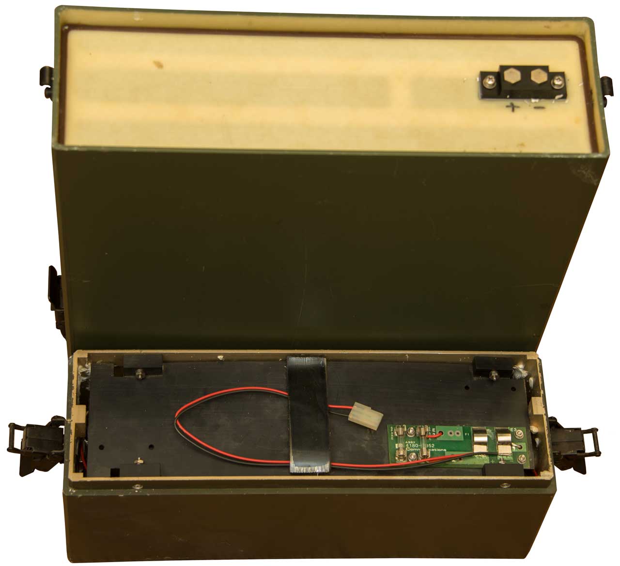
Fig 2
24 VDC rechargeable battery?
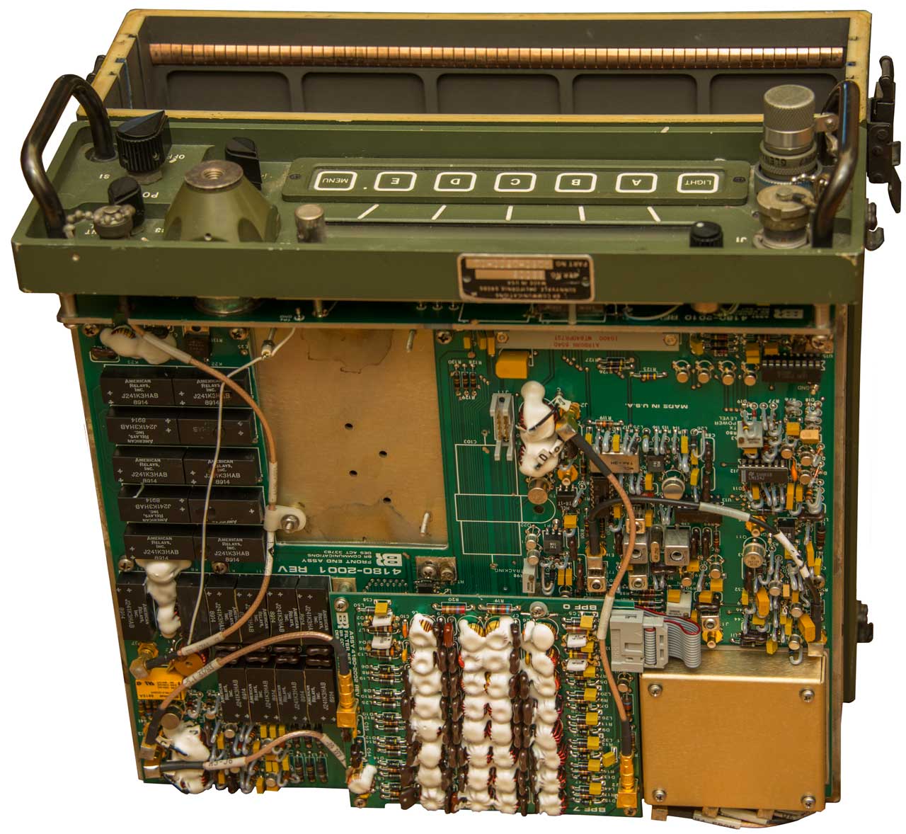
Fig 3
Combines IONCAP, VOACAP, ICEPAC with weather and a model of the electron density to come up with an overall model of HF propagation. Calls:5990845 Broadband fan cone direction finding antenna and array, E.D. Sharp, S.W. Hsi (TCI Intl), Nov 23, 1999, - bi-conical or disk-cone vertical polarization, but directional
4980924 HF radio communication systems with frequency management, A.P.C. Reed et al (Plessey), Dec 25, 1990 - models ionosphere
5230076 Ionospheric sounding, R.G. Wilkinson (HM UK), Jul 20, 1993 - bi-static hi power pulse system (chirp works much better)
5428358 Apparatus and method for ionospheric mapping, S.B. Gardner (Navy), Jun 27, 1995 - single site GPS receiver
5585800 Location-corrector for removing sun-induced effects in the global positioning system, S.R. Chubb, Dec 17, 1996 - Sun and theory of relativity
Back to Brooke's HF Propagation,
Electronics or Home
page
[an error occurred while processing this directive] page created 2 Feb. 2000.