LS 91
Chemtronics developed the LS 91 tester to test the BA-5590/U Dual 12 Volt sections, and
the BA-5598/U Used in the PRC-77 (but should NOT be used in the PRC-25) (Military TS-4403/U NSN
6625-01-359-5771),
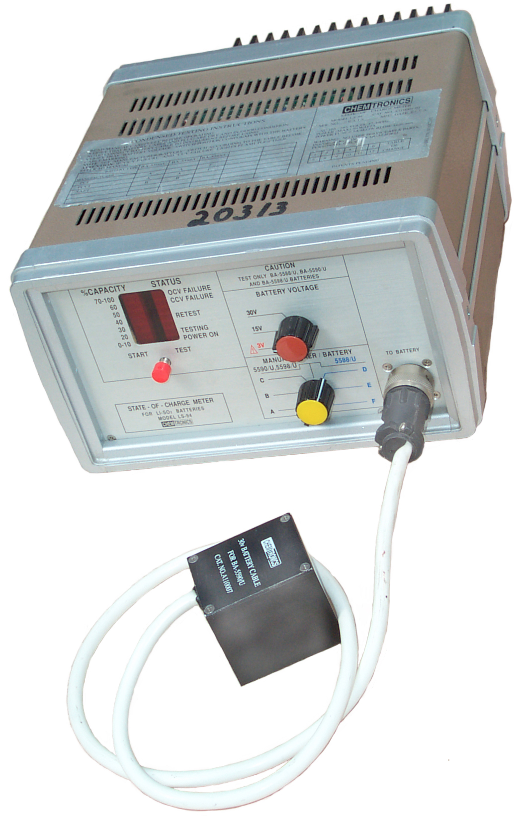
LS 94
Then added the BA-5588/U 15 Volt single section battery used in the PRC-68 family of squad radios and other equipment (the tester is the same, probably just a new EEPROM & test cable) to make the model LS 94 (Military TS-4403A/U NSN 6625-01-370-8278. The 3 Volt test is still a part of the LS 94 since the Army banned the BA-5598/U from use on the PRC-25 there is no need for it. Also since the 3 Volt section is just a tap one cell up from ground, when you test the 15 V section you are also testing the 3 volt section.
There are three LiSO2 batteries that are very commonly used in the US military:
|
|
|
|
|
|
|
|
|
|
|
|
|
|
|
|
|
|
|
|
Moltec also shows the EL-1132 as their product. Maybe Amrel is OEMing this electronic load.
The manual for the LS 94 is Chemtronics Document No. D110036-00, my copy is dated September 1992.
TM 11-5820-890-20-2 for the SINCGARS radio in chapter 7.3 has operating instructins for the LS-94 to test the BA-5590.
The discharge curves for LiSO2 chemistry are very flat in terms of loaded battery voltage vs. State-Of-Charge. This means that primary battery testers like the TS-183 or PSM-13 will not be able to tell anything except that the battery has reached its End-Of-Life.
Cables for the BA-5590/U and BA-5598/U have been made and are working.
The case is a very well designed ELMA BV34374-21 modular package. There are 4 major electrical components:
Front Panel with microcontroller printed circuit board
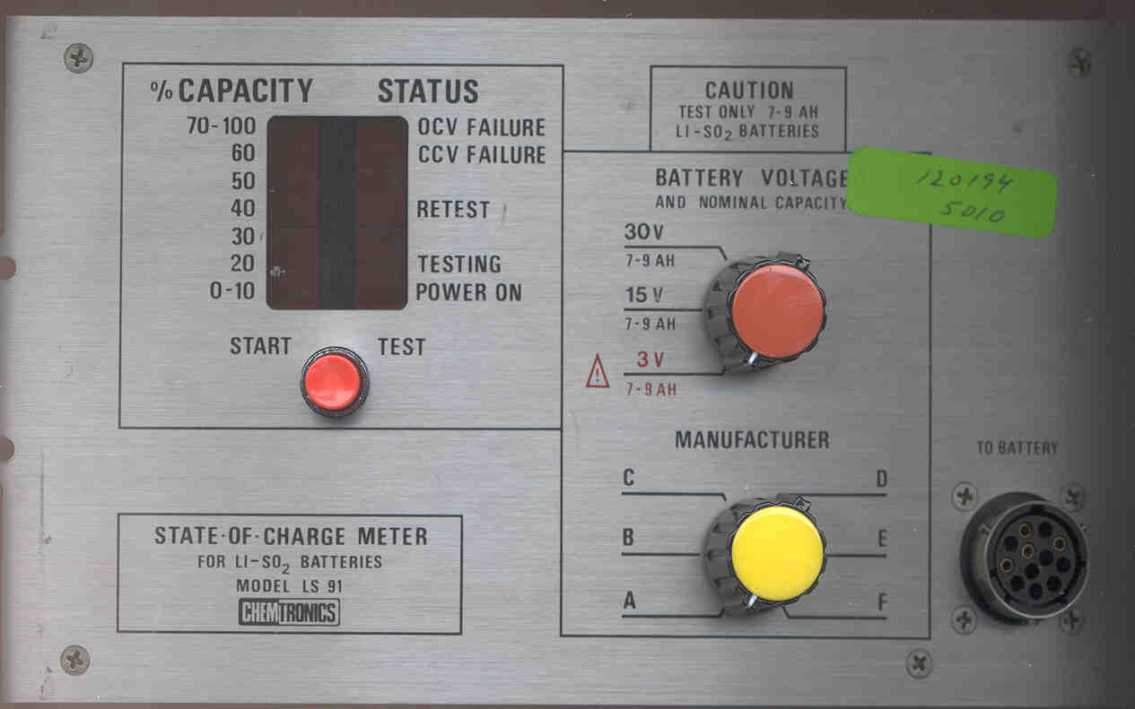
Photo of Front, Photo of Back of Front Panel -The P2 2x3 pin Molex connector goes to the Electronic Load.
The P3 1x5 Molex connector goes to the power supply.
The back panel has a cutout for some type of D connector. If it was an RS-232 interface then maybe the P4 connector and the missing parts surrounding it are for this interface.
An Intel 87C51 is in the lower right corner running from a 6.000 MHz crystal.
There are a couple of ULN 2803A high current drivers next to the 87C51 on the lower right edge.
An AD650KN (voltage-to-frequency converter) is just to the left of the 87C51.P1 connects the test socket on the front panel to the PCB with 4 wires:
There are high power components in the upper left corner: Fuse, resistor, diode, 6-pin Omron G6C-2114P-US relay.
- A-Blue - + battery voltage sense terminal
- C-Brown goes to the Fuse then to the power diode for application of the batt hot side (+ battery) load
- H-Yellow goes to the 0.1 Ohm power resistor then to ground. Probably to measure the current through the - battery.
- M-White - Self test terminal. Should read (with respect to socket "C" ground):
It reads 9.992 on a Fluke 87 DMM that has 10 M Ohm Rin (in the extended resolution mode (hold down yellow then switch on).
- 9.982 to 9.998 Volts with a meter input resistance of 10 M Ohms
- 9.983 to 9.999 Volts with a meter input resistance of 11 M Ohms
- 9.992 to 10.008 Volts with a meter input resistance greater than 1,000 M Ohms
The PCB has the markings: LS91MB (Mother Board) Rev 2.3, Assy. 1041006, Chemtronics (C) 1989 1990. SN? 051
On the side is R(reversed)U 94V-0 and the Motorola (circle M) mark, why?
The PCB is a nice double sided design.There are 4 each Bar Graph LED displays to show the state of charge on the front panel.
Although the Manufacturer Switch on the front panel shows 6 positions (A through F) the mechanical stop has been set to restrict the setting to A, B or C. There are only 3 manufacturers listed on the lid and only A and B codes are shown. Why the C position?
F2 (Fuse 2) is not installed. J1 (a 20 pin machined DIP socket is empty, maybe a test socket?
There are sockets for R13 through R22 with only 3 resistors installed and jumpers in the remaining spaces. Maybe this State of Charge Meter was designed in a generic way and customized for specific battery types and manufacturers.
Lambda LVT-40E-144 open frame power supply to drive front panel
Purple & Blue 105 to 250 VAC 47 to 63 Hz input
Yel/Grn EarthRed +5 Volts +/- 1% 1.0 A @ 60 deg C
Black common
Orange +15 Volts +/- 5% 0.15 A @ 60 deg C
Green Common 2
Yellow -15 Volts +/- 5% 0.01 A @ 60 deg CElectronic Load on Rear Panel with Massive Heat Sinking
The small PCB is marked LS91EL (Electronic Load) Rev2.3 Chemtronics (C) ASY 1041007 1989 TYPE 1 94V0 S/N 060 the two power devices (Q300 & Q301 have markings of G, D, S (Gate Drain Source). There is a Motorola (circle M) mark on the PCB, why?Connector on Front Panel
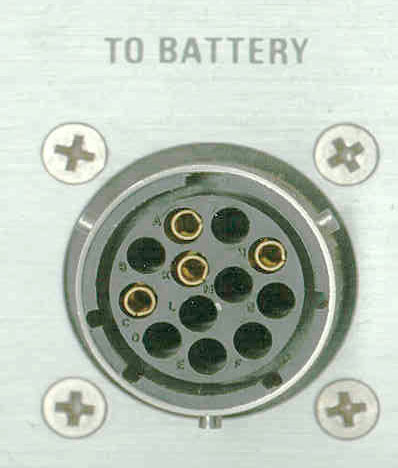
The connector has "BRUNDY" but no other markings. It is made of plastic and has 12 holes, but only 4 have sockets isntalled. The socket inside diameter is about 0.075". The outside shell diameter is about 0.875" and there are 3 pins to hold the mating connector. There are 5 slots to key the mating connector.Brundy is now called Framatome Connectors Inc (FCI) - the cable plug is a UTP61412P (Newark 16F5751) empty connector shell, cable clamp is a UTG14AC (Newark 16F5824), the pins are FCI part number SM14ML1TK6, but Newark only sells 16F5678 in bags of 100 for almost $50 each bag. A special criping tool is not required. You can use a standard pliers type crimping tool designed for common crimp connectors
1. Remove the flat "wing" from the back of the pin (a single pin was cut from a continous roll of pins).
Wiring for the BA-5590/U 30 Volt (tests both 15 Volt sections in series) test cable
2. strip 1/2" of the wire insulation and do not twist, leave the bare wires straight (makes them smaller in diameter so AWG 14 stranded wire will fit, AWG 16 is too big and some strands will need to be folded back under the crimping wings.)
3. crimp the rear part of the pin over the bare wires, do not crimp any other part of the pin
4. slip connector back shell over wires
5. install the pins into the back side of the connector shell until the fingers snap. (if you make a mistake it's possible to use a drift and pound on the point of the connector. This may ruin the pin and cause minor damage to the connector shell. The Radio Shack 274-233 is too big in diameter to work, don't bother to try.)
6. screw the back shell onto the main connector
7. install the cable clamp
- Tester socket "A" <-> battery + (BA-5590 pin 5)
- Tester Socket "C" <-> battery + (BA-5590 pin 5)
- Tester Scoket "H" <-> battery - (BA-5590 pin 1)
battery (BA-5590 pin 2 jumpered to battery BA-5590 pin 4) (no tester connection, jumper to connect two batteries in series to get 30 Volts)
When the connector that is specific to the battery is connected to the tester and battery and the START TEST button is pressed momentarily, the POWER ON and the TESTING LED are on for about 100 seconds then the TESTING LED turns off and one of the % CAPACITY LEDs turns on. Note that the highest capacity reading is 70 to 100%. The military likes to see this LED on when deciding if they are going to recycle a LiSO2 battery.
The Condensed Testing Instructions on the lid say in essence to:The instrument applies a specified load to the battery and monitors the terminal voltage.
- Connect battery to cable and instrument
- set Battery Voltage to match cable used: 30, 15 or 3 (implication is that different cables connect to different parts of multi voltage battery.
- Set Manufacturer A (PCI or PCCI) or B (Saft)
- Press the Start Test button.
The OCV (Open Circuit Voltage) Failure LED lights if:
The CCV (Closed Circuit Voltage) Failure LED lights if:
- the battery is totally depleted
- incorrect or undetermined setting of the BATTERY VOLTAGE selector switch
- battery polarity is reversed
- battery not properly connected (cable fault)
- no cable connected to tester
RETEST when turned on with a % CAPACITY reading
- the battery voltage is too low (almost fuly depeleted
- the battery has high internal resistance
The tester makes not only electrical measurements on the battery but also measures the room temperature and uses that data to correct the displayed SOC.
- the battery capacity may be higher, do another test (3 tests maximum in a row) to see the capacity
9 Aug. 2004 - When I tried to use the tester right after it was brought indoors from storage, shortly after starting a test both the OCV & CCV LEDs would blink. After storing the testers indoors they still showed this problem. But after powering the LS-91 tester overnight it worked properly. Now will see if leaving the LS-94 on for some time gets it also working.
11 Aug. 2004 - the LS-94 (TS-4403A) still blinks the OCV & CCV lights when I try and test a BA-5590 that checked in at over 70% on the LS-91. If you know what this blinking light pattern means please let me know.
PSM-13 for a number of dry batteries (BA-4386/PRC-25 included)Back to Brooke's Products for Sale, Battery, Electronics, Military Electronics Information, Home page
TS-183 Dry Battery Tester, does not work on the BA-4386/PRC-25) or on any LiSO2 battery
This is the [an error occurred while processing this directive] time this page has been accessed since since 23 March 2002.