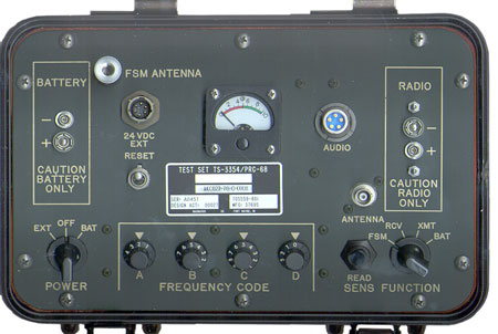

On tge right side is a simulated battery connection to power the radio under test. In order to get the PRC-68 radio to seat the module housing needs to be removed, which is a good idea since adjustments will be made. When using a PRC-126 with the TS-3354 just use the battery on the PRC-126 and do not connect it to the TS-3354 for power, just use the BNC ANT cable and the Audio Cable. The main reason for the pins is to prevent a battery from being connected to these terminals and frying the inside of the test set.
The Frequency Code switches are set for 51.0 MHz.
The Following accessories should be
under the lid:
The 046833.pdf manual has schematic diagrams for the synthesizer 914265-801 that similar to the one used in the PRC-68 but has a ribbon cable going to the front panel instead of the small switches that are on the module for the PRC-68, there is a bracket soldered to the module to hold the ribbon cable. It also has the schematic diagram for the 1A7 VCO module 917833-803. The VCO module is right from the PRC-68.
Pin D of the power connector is for +24 VDC and pin A is ground, no other pins are used.
Only pin B (ear) and pin A (ground) are used on the AUDIO connector.
There is also a Cinox T154 12.000 MHz oscillator that appears to be a high quality oven unit.
Settings for the Channel Switches
The Channel switches A, B,C and D control the internal 1A9 Synthesizer module that has these switches located on the front panel rather than be on the module itself. (this table was printed on the battery cover for the PRC-68) The programming table looks like:
|
|
|
|
|
|
|
|
|
|
|
|
|
|
|
|
|
|
|
|
|
|
|
|
|
|
|
|
|
|
|
|
|
|
|
|
|
|
|
|
|
|
|
|
|
|
|
|
|
|
|
|
|
|
|
|
|
|
|
|
|
|
|
|
|
|
So to set the TS-3354 on 51.0 MHz the switches need to be set:
A=2, B=5, C=5, D=0.RCV Function

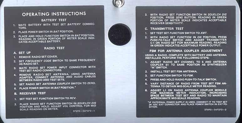
OAI Electronics - (CAGE 22887) web page under construction, nothing there yetHow to use this function is not intuitive. It is also in the instructions in the lid. The other functions need no explanation.
Note that with no radio connected to an operating TS-3354 with the Function switch set for RCV the meter will read about "9".
For more on testing FM radios for receive sensitivity see: SINAD FM Receiver SensitivityTo use the RCV Function:
- Set the radio for 50 Ohm operation. For a PRC-126, PRC-128, PRC-136 set ANT switch to "50" position and use the 68AA, not the antenna adapter that's part of this set.
- Connect the radio to the TS-3354 using the Audio and ANTENNA cables, you do not need to mount the radio on the TS-3354
- Connect a battery to the TS-3354 with the POWER switch to BAT, or connect an external supply to the 24 VDC EXT connector, MS3114E10-6P is on the test set so you will need a MS3114E10-6S to make the cable (not tried Mouser, Digi-Key ). This takes in 19 to 32 VDC.
- make sure the TS-3354 RESET switch is in the up position
- Select RCV Function
- Turn on the radio with the volume control at it's minimum volume position
- Activate the radio Squelch Disable (PRC-68 rotate PWR OFF -ON switch to SQUELCH DIS), (PRC-126, press SQ DSBL), other radios may require removing the module cover to disable squelch.
- Slowly increase the radio VOL until meter on TS-3354 reads 5 (half scale)
- Press READ SENS on TS-3354 and the meter should go into the Green range (5 to 10) indicating adequate receiver quieting
CAGE 37695
RAYTHEON CO
DBA RAYTHEON SYSTEMS
CO
1010 PRODUCTION RD
FORT WAYNE, IN 46808-4106
Litton - Tactical
Communication Interface Modems -
Return to Brooke's PRC68, Products
for Sale, PRC68 Family, PRC68 Battery, Electronics
or Personal Home page
[an error occurred while processing this directive] page created 2000.