Battery Top Power Suppy
© Brooke Clarke 2005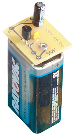 |
 |
 |
| Fixed Output
Voltage |
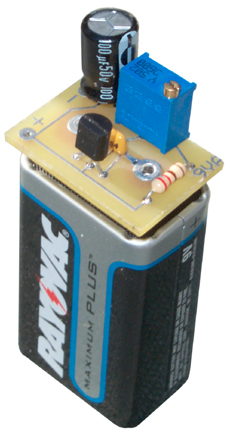
Adjustable
Output Voltage |
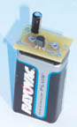
BTPS on 10
AA holder |
|
|
|
| Fixed Output
Voltage |
Adjustable
Output Voltage |
BTPS on 10
AA holder |
 It turns out that there are a number of TO-92 packaged
fixed output voltage regulators and so far they all have the same
pinout so that a single PCB will work for all of them. The
table below is based on the offering by National Semiconductor, but I'm
sure that are many companies that offer TO-92 packaged voltage
regulators. Some of these may have a price - performance point
different from the NSC parts.
It turns out that there are a number of TO-92 packaged
fixed output voltage regulators and so far they all have the same
pinout so that a single PCB will work for all of them. The
table below is based on the offering by National Semiconductor, but I'm
sure that are many companies that offer TO-92 packaged voltage
regulators. Some of these may have a price - performance point
different from the NSC parts.
Model |
Voltage |
Imax |
Iq typ1 |
Vin min |
Vnom
-1% Measured 100 Ohms |
1k load |
100 load |
47 load |
Volts |
mA |
uA |
Volts |
|||||
| LM2936Z-5.0 | 5.0 |
50 |
9 |
5.20 |
5.14 |
5.025 |
5.002 |
0 |
| LM2936Z-3.0 | 3.0 | 50 |
15 |
3.20 |
||||
| LM2936Z-3.3 | 3.3 |
50 |
15 |
3.50 |
||||
| LP2950CZ-3.0 | 3.0 |
100 |
75 |
3.45 |
3.27 |
3.000 |
3.000 |
3.001 |
| LP2950CZ-3.3 | 3.3 | 100 | 75 | 3.75 |
||||
| LP2950CZ-5.0 | 5.0 | 100 | 75 | 5.45 |
||||
| LP2950ACZ-3.0 | 3.0 |
100 |
75 | 3.45 |
||||
| LP2950ACZ-3.3 | 3.3 |
100 |
75 | 3.75 |
||||
| LP2950ACZ-5.0 | 5.0 |
100 |
75 | 5.45 |
5.31 |
5.002 | 4.999 | 5.004 |
| LM2931Z-5.0 | 5.0 |
100 |
400 |
5.3 |
4.93 |
4.929 |
4.929 |
4.957 |
| LM2931AZ-5.0 | 5.0 |
100 |
400 |
5.3 |
||||
| LM78L62ACZ | 6.2 | 100 | 2000 | 7.9 |
||||
| LM78L05ACZ | 5.0 |
100 |
3000 |
6.7 |
6.56 |
4.975 |
4.974 |
4.969 |
| LM140LA-5 | 5.0 |
100 |
3000 |
7.0 |
||||
| LM340LA-5 | 5.0 |
100 |
3000 |
7.0 |
| Model |
Voltage |
Imax |
Iq |
Vin
min |
| 6.2 |
100 |
|||
| 78L09ACZ |
9.0 |
100 |
||
| 78L12CZ |
12.0 |
100 |
||
| 15.0 |
100 |
 By using the LM317L regulator
an adjustable output power supply can be made. With a single 9
Volt battery and stock value resistors you can get 1.25 to 7.7 volts,
settable to about 1 millivolt when a 25 turn pot is used.
By using the LM317L regulator
an adjustable output power supply can be made. With a single 9
Volt battery and stock value resistors you can get 1.25 to 7.7 volts,
settable to about 1 millivolt when a 25 turn pot is used.| Output |
Input for
-1% (open) |
Iopen
ma 2 |
| 20 |
21.1 |
4 |
| 15 |
16.22 |
4 |
| 12 |
13.28 |
4 |
| 9 |
10.33 |
4 |
| 6 |
7.36 |
4 |
| 5 |
642 |
4 |
| 3.3 1 |
4.76 |
4 |
| 3.0 1 |
4.43 |
4 |
| #
Batt |
Vmax |
Vmin |
Uses |
Adj
Range |
| 1 |
9 |
4.8 |
3.0, 3.3, 5.02 |
1.25 - 9.0/4.8 |
| 2 |
18 |
9.6 |
102 |
1.25 - 18/9.6 |
| 3 |
27 |
14.4 |
10, 12, 152 |
1.25 - 27/14.4 |
| 4 |
36 |
19.2 |
1.25 - 36/19.2 |
These
come in different number of cells
connected in series thus different output voltages. So it's
possible to match up the flat battery voltage with the minimum Vin spec
for the regulator. Alkaline AA cells have much more capacity than
the very small cells used in a 9 volt battery and are better suited for
use where higher currents are being drawn. Converting
the AccuLab ALS-208 into a
stand alone Hall Effect magnetic field
probe.
Converting
the AccuLab ALS-208 into a
stand alone Hall Effect magnetic field
probe.| Range |
DMM |
| +/- 2 G |
2.3 to 2.9 |
| +/- 20 G |
2.06 to 2.10 |
| +/- 200 G |
2.005 |
 Powering
the FLC-100 Fluxgate magnetometer. A couple of pair of CAT5 LAN
cable has been pulled out of the jacket and the Orange pair used for 5
volts and the blue pair used for the DC output. Zero volts out
for no field and a scale factor of 1 v / 50 uT. Current use is
for testing zero magnetic shielding
cans. This sensor has an advantage over others in that there is a
defined output for no field. The FGM-3 type sensor has a
continuos change of frequency as the field changes, but the frequency
for no field needs to be determined by the user (not a simple task).
Powering
the FLC-100 Fluxgate magnetometer. A couple of pair of CAT5 LAN
cable has been pulled out of the jacket and the Orange pair used for 5
volts and the blue pair used for the DC output. Zero volts out
for no field and a scale factor of 1 v / 50 uT. Current use is
for testing zero magnetic shielding
cans. This sensor has an advantage over others in that there is a
defined output for no field. The FGM-3 type sensor has a
continuos change of frequency as the field changes, but the frequency
for no field needs to be determined by the user (not a simple task).| Fixed Output |
Adjustable
Output |
| 1 Batt |
1 Batt |
| 2 Batt |
2 Batt |
| 3 Batt |
3 Batt |
| 4 Batt |
4 Batt |
This is the [an error occurred while processing this directive] time this page has been accessed since since 17 Nov. 2005.