Gamewell Fire Alarm Box
© Brooke Clarke 2022 - 2025 |
 |
 |
Description
Photos
Fire Call Box
Light
Code Wheel
Patents
Traffic Lights
Diaphone Air Horn
Bells & Gongs
San Francisco Cable Car Co. Bell
Faraday 4070 Striker w/o Bell
Cat. No. MB-3 4" Bell
Gamewell 70875 Vibratory Bell
Faraday DG-4 Dual Gong
Gamewell M-1008 Tap Gong
100mA Power Supply
Edwards 55 Bell
Door & Desk Bells
Stewart Model 149A Army Chemical Warfare Service Siren
Gamewell Fog Bell
Pen Registers
KS-3106
Horni Signal Strip Printer
Time Register
Related
References
YouTube
Links
Background
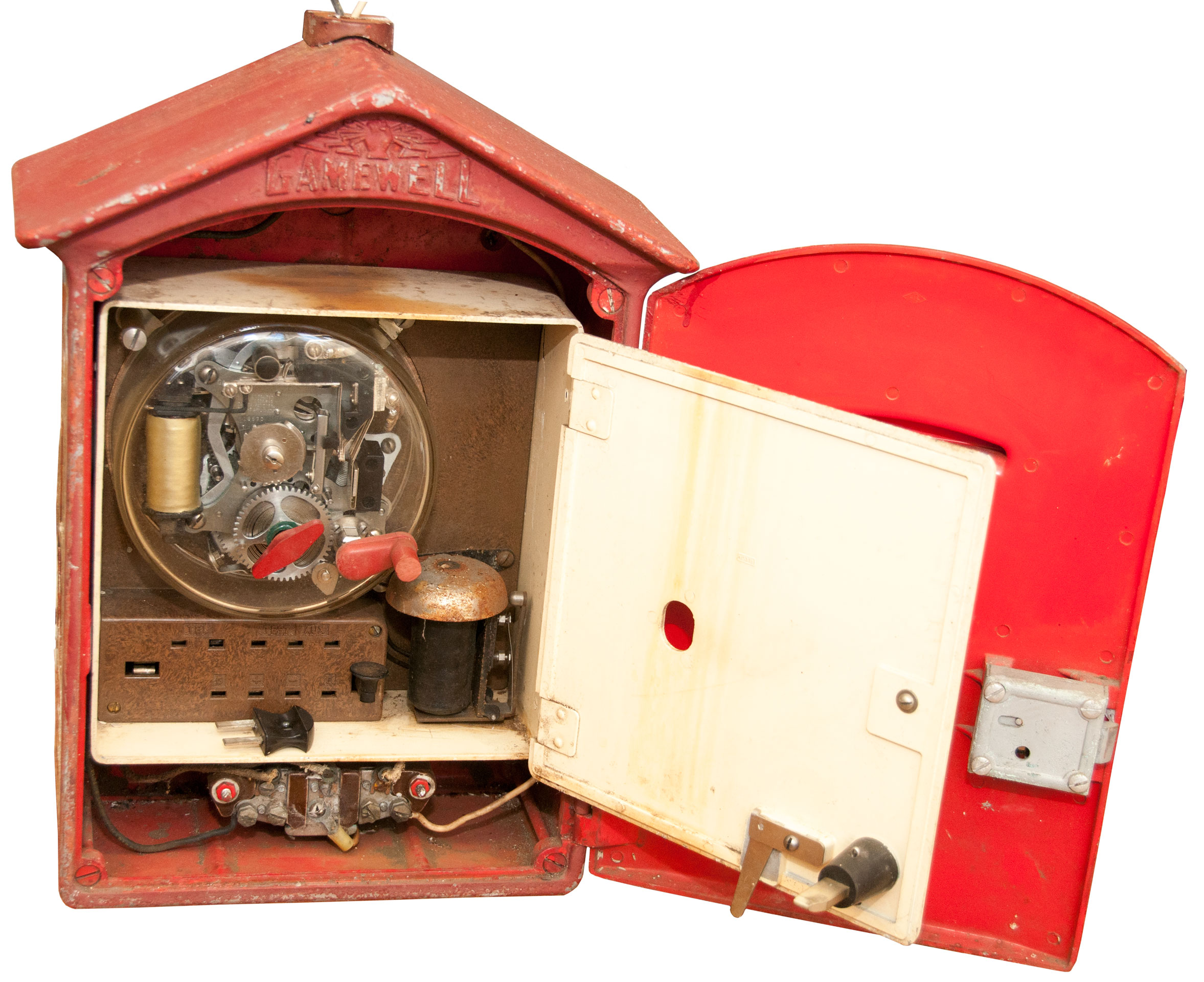
This is a Fire Alarm Call Box (Wiki) made by Gamewell (need to check specific manufacturer name when it gets here. There were similar police call boxes with a telephone connected directly to the local police station. The Fire alarm call boxes have what amounts to a preprogrammed telegraph system that sends a special character that is unique to the box and therefore it's location.
Gamewell is known for Fire and Police alarm call boxes (Wiki) and systems. Note that San Francisco (SF Gate), Boston and New York still use call box systems because they continue to work in cases where cell phones fail (think 9/11 or other disaster when the phone system is overloaded).
WARNING
When waiting for an alarm the box is a dead short circuit. Connecting any power supply to the line terminals can damage the box. Only a current limited loop power supply should be used. For proper operation of the call box there needs to be a physical resistor as part of the current limiting and the loop voltage needs to be >= 30 Volts.
Description
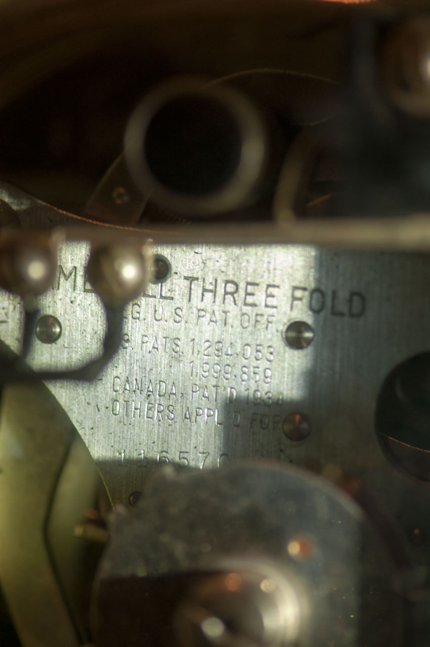
The serial number 116570 (see Fig 4 below) corresponds to a manufacture year of 1941.
Three-Fold
This feature was introduced in 1931. The prior signaling mechanism are now called Single-Fold or 1-Fold.
1. Under normal conditions, alarms are transmitted over closed metallic circuits without the use of grounds or other conditions.
2. On a broken wire circuit, any operated box will automatically apply a ground and transmit the alarm over whichever side of the circuit the box remains connected with the central station.
3. In cases where boxes are accidentally excluded from the normal metallic circuit by short circuits, boxes operated under such conditions will automatically apply grounds and transmit alarms correctly. It is a fact worthy of serious consideration that a closed metallic circuit may appear to be in normally operative condition and yet have one or more boxes short-circuited or shunted out.
Unless entirely disconnected from the fire alarm central station by multiple breaks or grounds, the Three-Fold fire alarm box will correctly transmit and the central station reliably receive alarms despite any of the troubles listed below:
a. Open Circuit
b. Grounded Circuit
c. Box short circuited
d. Entire circuit shunted out
e. Circuit open and grounded
f. Circuit open and box short circuited
g. Circuit open and entire circuit shunted out
h. Disabled non-interference magnets.
Major Components
The outer box with instructions and false alarm prevention features.
The inner box containing the signalling mechanism and test panel.
The terminal block to connect the signalling mechanism, the light to the loop circuit and ground.
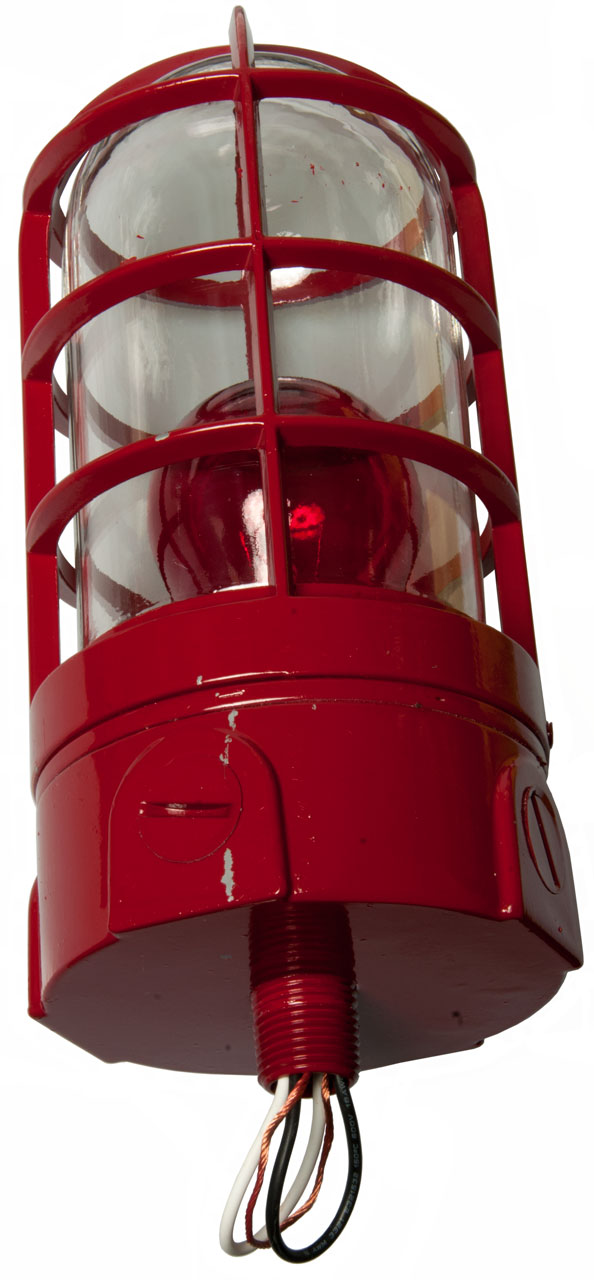
The lamp above the box.
Theory
Normal Mode
Inside the box Line- is shorted to Line+, no connection to ground. (see WARNING above).
Note the way my Street Box is wired the black and white wires coming out the top light hole are connected to Line+ and Line- respectively, so the light is normally off. That means that light will flash the code being transmitted by the box. It takes a few minutes to send the code four times so people near the box will know that the alarm is being sent.
"Supply Voltage of circuit in which this box is connected should not be less than 30 V." I expect that this box is wired in a manner that's similar to how telegraph, teletypes, stock tickers , Western Union 5A Stock Ticker, and Western Union Clocks ( 1 & 2) are wired. This involves a DC power supply on the order of a couple hundred volts with a resistor to limit loop current to 100 mA. Note that the resistor is mandatory since the time constant of a circuit with inductance (electromagnetic coils) and resistance depends on the ratio L/R. It can NOT be replaced by a current limiter circuit. This means adding resistance to the circuit makes it work faster, snappier, stronger. Circuits that use a voltage supply where the voltage is chosen to supply the correct current will be sluggish and not sound good. This is very different than a circuit with capacitance and resistance where the time constant gets longer with the increase of either R or C.
Test Mode
Opening inner door pulls the plug on the back of the door removing Line+ from the signaling mechanism. Now the tap bell coil appears across the Line+ to Line- terminals, i.e. about 16.5 Ohms. When the Test Plug is installed in the Test socket a 65 Ohm resistor is additionally connected between Line+ and Line-. The parallel combination of 16.5 and 65 Ohms is 19 Ohms, I read 14 Ohms (Tap coil measures 16.7 and Test shunt measures 66.7 so should be 13.6 Ohms, i.e. negligible error.
In test mode when the alarm is pulled the mechanism works and the tap bell confirms that but the central office does not see an alarm.
Normal Signaling Mode
The signal consists of a series of "dots" and the number and spacing of the dots is the message. For example this Gamewell Street Fire Alarm Call Box is box number 153. The signal it sends is dot - - dot - dot - dot - dot - dot - - dot - dot - dot where "-" is some space and "- -" is a longer space. Note unlike a normal telegraph there are no dashes.
Photos
Fire Call Box
Fig 1
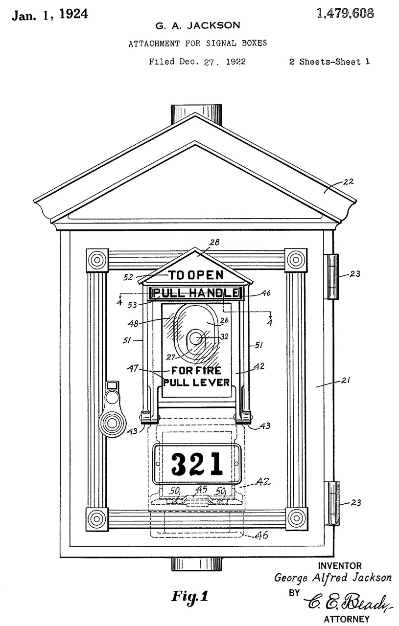
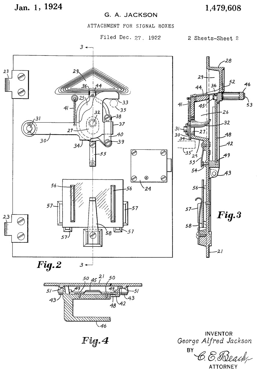
Fig 2 See patent 1479608 for inside of door mechanism
Fig 3
Fig 4 Patents
GAMEWELL THREE FOLD
Reg. U.S. Pat. Off.
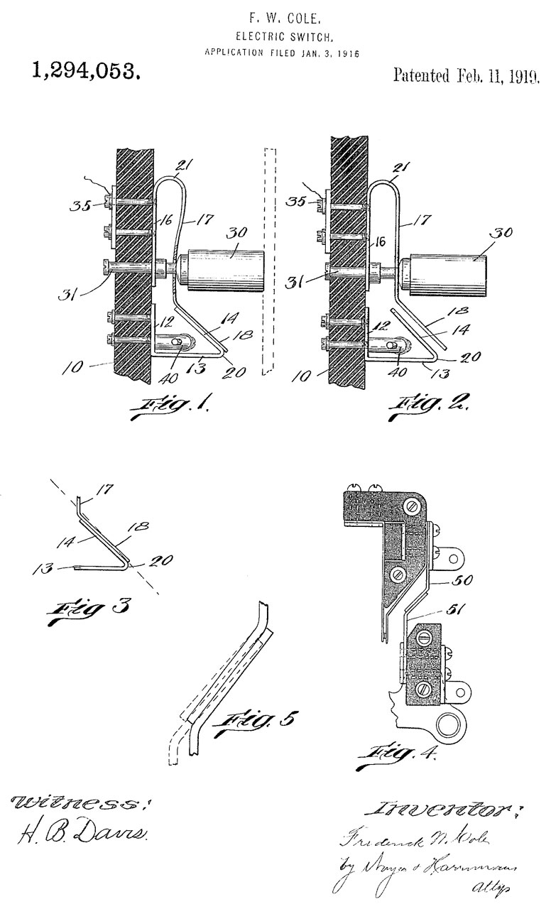
U.S. Pats. 1,294,053
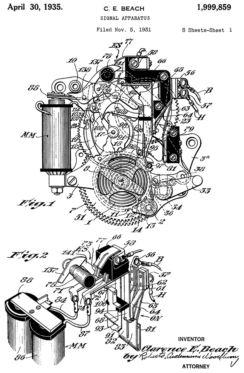
1,999,859
Canada, Pat'd 1934
Others Appl'd for
116570
Fig 5
Test Plug stored on bottom of inner door.
Note when the plug is removed lever hinges down preventing inner door from closing.
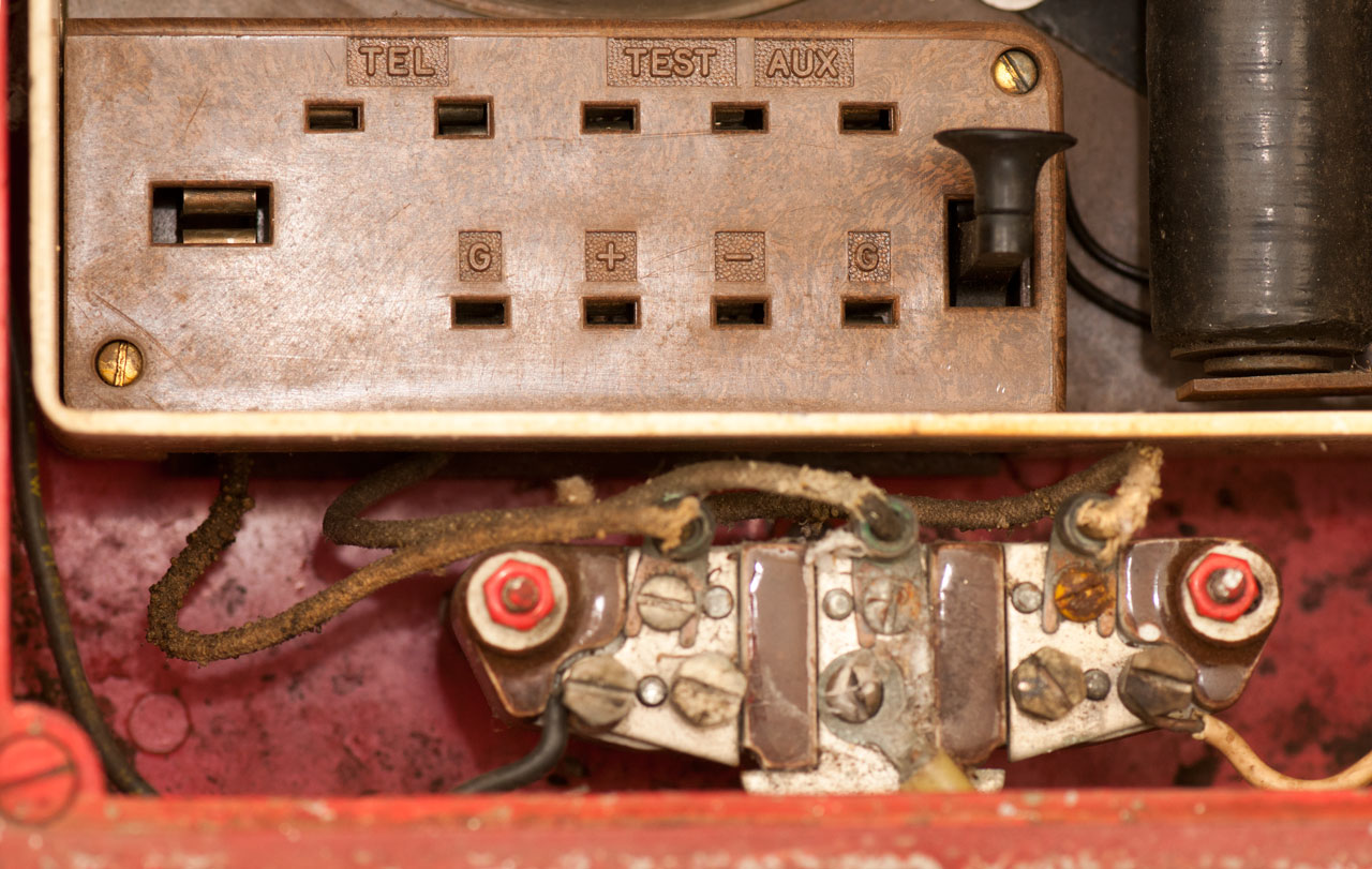
Fig 6 Test Panel (top) and Line terminal block (bottom)
Street Box (does not have Master Box equipment).
3-Fold Street Box Wiring Diagram
Modified version of Silent Test Circuit
pg 62 of Tucson Fire Dept. Gamewell Information
Fig 7 Test Panel cover removed
Fig 8 Signal Apparatus
The three screws probably also hold the inner box to the outer box as well as the glass to the back panel so care needed when removing them.
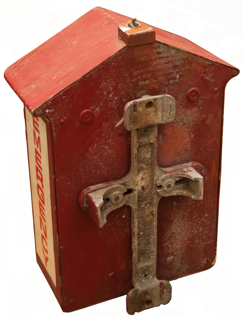
Fig 9 Back with telephone pole bracket and "top pipe connector".
Someone has sawed off the light pipe/conduit flush with the top. I'm trying Kroil to get the pipe out to allow installing a light.
Fig 10
Support:
"Shur Hsi.C.223
Support Horn1 Signal"
Brackets: 2 each: "HFSC 223A"
Light
This appears to be functionally correct although it does not have any manufacturer's markings.
Fig 1
Code Wheel
The code wheel has a bump for each gong ring and spaces between counts. The Code is either 3 or 4 digits and is repeated a number of times.
YouTube:Gamewell Fire Call Box 152 & M-1008 Tap Gong, 0:55 - Code: 152.
PE-101 Dynamotor
The Gamewell code wheels do NOT fit the PE-101 dynamotor.
I have the PE-101-C Dynamotor on order (2022Sep7). It's part of theABA-1 IFF (Wiki: Mk IV IFF) set. It can accept code wheels that seem to be very similar to the Gamewell code wheels.
The PE-101 is missing the code wheel drive hardware and the electrical contacts and related wiring. So it's not possible to tell if the gamewell code wheels can be used. My guess is that they are different.
If you have documentation on the PE-101 let me know.
Labels
Signal Corps U.S. Army
Dynamotor Unit
PE-101-C
Serial No. 23706
Order No. 1488-PHIL-42
Supplied by
General Electric Company
Bridgeport, Conn.Dynamotor
No. 286?? Type 4151 S.S. 104
Temp. Rise: 40C R.P.M. 4800 Duty: Con
Input Volts: 13//26 Amps 12.6/6.3
Output D.C. Volts: 400 Amps: .135
800 .02
Output A.C. Volts: 9 Amps 1.12
Cycle: 80 P.F. 95%
Manufactured by
Wincharger Corp. - Sioux City, Iowa.
Fig 1 ABA-1 IFF Code Wheels
The MC-247 wheel is about 0.89" dia.
Fig 1
Fig 2
Fig 3
Fig 4
Fig 5 Missing the code wheel drive hardware
& Contacts/wiring
Fig 6 from an eBay listing, different end design
Fig 7
Gamewell Code Wheel This wheel is coded for 2 - 1 - 2 - 7.
Fig 1 Wheel Assembly Top
Fig 2 Wheel Assembly bottom
Fig 3 Wheel Assembly parts
Also see the APX-6 IFF Transponder.


Box & Related Patents
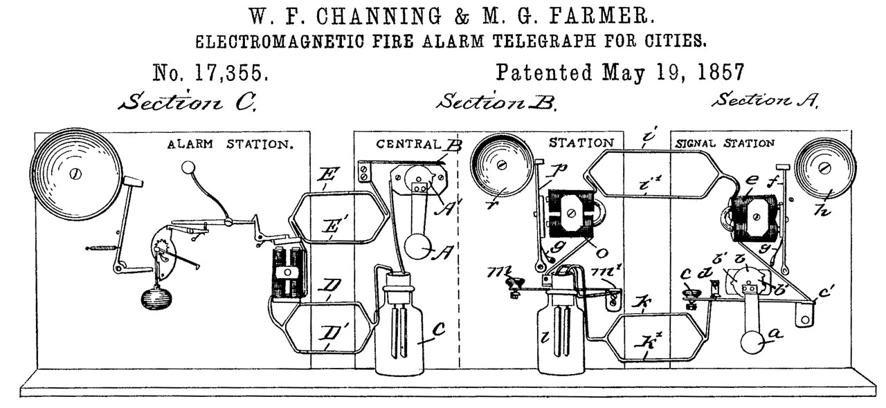
17355 electromagnetic fire-alarm telegraph for cities, W.F. Channing (Wiki) & M.G. Farmer (Wiki), May 19, 1857, 340/297; 340/298; 340/299 - Signal Station contains wheel (b) that can generate dots and dashes to signify the fire district and the box within that district. A pen register may be used to record the alarm. The Central Station repeats the alarm signal using a bell. The Alarm Station, located in a bell tower, broadcasts the alarm signal over a large area.
Note the central station rings the alarm in the bell tower, it is not the Signal Station (call box).
The Alarm Station uses a flexible arm on the clapper which when at rest is held away form the bell.
All outside wires have a redundant wire so if one wire opens the other wire will allow the system to work.
The Central Station and Signal Station (call box) bells ring when the circuit is broken and there does not appear to be a provision to pull the striker away from the bell to allow it to ring, ie the clapper hits the bell and stays there until the current pulls it away. (maybe the dots are very short?)
"
RE6239 Improvement in electro-magnetic fire-alarm telegraphs for cities, Jan 19, 1875, 340/297 (consecutive numbers all on same date)
"
RE6240 Improvement in electro magnetic fire-alarm telegraphs for cities 340/297 "
RE6241 electro-magnetic fire-alarm telegraph for cities, W.F. Channing & M.G. Farmer, assigned to W.F. Channing, January 19, 1875, 340/288 - includes provision to stop wheel (b) so the circuit is closed, thus allowing other signal stations to sound a different alarm.
164406 Fire-Alarm Signal-Box, R.N. Tooker, June 15, 1875 340/297; 340/308 - key-less door to save time getting the key from a neighbor.
223248 Fire-alarm-telegraph repeater, E. Rogers & M.G. Crane, , Jan 6, 1880 340/291 - joker repeater: call box to Central station - Repeater to engine house - base plate with towers and gears
253080 District-telegraph system, C.F. McCulloh, Jan 31, 1882 340/292 - a line break is instantly signaled
272645 Signaling Apparatus for District and Fire Alarm Telegraphs, T.A. Casey, J.H. Bunnell & Co, Feb 20, 1883 340/309 - Hand crank - gears - code wheel
338593 Fire-alarm, A.C. Gordon, Mar 23, 1886 116/5; 116/156; 116/106 - lines run from different rooms and hold a weight above a lever. If any line breaks it's weight rings the operator. (The operator would hear an off hook phone?)
253759 Signal Box for District and Alarm Telegraphs, G.M. Phelps, Feb 14, 1882, 340/309 - hand crank drives gears to code wheel.
298588 Individual signaling Apparatus, T.D. Lockwood, Apr 8, 1884 30/349; 30/193 - code wheel & bell at each station
329188 Testing apparatus for fire and police telegraph systems, Lewis H. McCullouch, Oct 27, 1885 340/292; 178/109 - non-interference and working with derangement of outside wiring
350804 Fire Alarm Telegraph System, S.A. Chase, Oct 2, 1886, 340/293; 340/292 - uses the terms "vibrating gong" to indicate a break in the line and "Electro-mechanical Gong" for the box signals
Calls 342576 Telegraphic Relay, May 25, 1886, 335/181 - which is a standard sensitive relay intended for fire alarm use
394784 Electronic Signaling Apparatus, G.F. Milliken, Gamewell Auxiliary Fire Alarm Co, Dec. 18, 1888 340/298 - bell that keeps ringing, not a single strike gong.
375569 Automatic Cut-out for Fire Alarm Box Controller, C.D. Rogers, Dec. 27, 1887, 340/295 -
415578 Fire-alarm-telegraph repeater, F.A. Skelton Nov. 19, 1889 340/291 - joker repeater
420173 Electric fire-alarm system, J. Speicher, Newark District Telegraph Co, Jan 28, 1890, 340/291; 178/3; 83/61; 178/92 - fast to station, slower to bell tower, non-interference
421853 Automatic fire-alarm system, G.F. Bulen, Feb 18, 1890, 340/535; 340/593; 374/189; 340/293 - thermostats cause code wheel to send code of the circuit with tripped temp. sensor.
453982 Fire Alarm Telegraph, G.F. Milliken, Gamewell Auxiliary Fire Alarm Co, June 9, 1891, 340/305; 340/299 - auxiliary circuit resetting?
463608 Automatic Fire Alarm System, G.W. Brown, Nov 17, 1891, 340/590; 340/506 - local not district telegraph
466604 Electrical Signal Box, T.F. Gaynor, Gaynor Electric Co., Jan 5, 1892, 340/308; 340/294; 340/299; 340/288; 340/298 - includes tap bell, function knob, and code wheel gearing, pull down lever behind front door,
540422 Signal-Transmitters Apparatus and System, H.A. Chase, Metropolitan Duplex Fire and Police Signal Co, June 4, 1895, 340/294; 340/297; 340/303; 340/292 - combined fire & Police,
546036 Signal Box, N.H. Suren, Gamewell Fire-alarm Telegraph Co, Sept. 10, 1895, 340/295 - opening door starts the alarm, uses code wheel
546037 Signal Box, N.H. Suren, Gamewell Fire-alarm Telegraph Co,Sept. 10, 1895, 340/295; 340/297 - about the Cut-out switch - has the elements (signal mechanism, line terminal block, test panel with telegraph key, tap bell) of this box only arranged differential.
551123 Successive Non-Interfering Signal Box, W.H. Kirnan, Dec 10, 1895, 340/295 - Telegraph key mounted on small block where you press in instead of down like on the above box.
563586 automatic Repeater, J.W. Frost, July 7, 1896, 340/291 - for district fire alarm systems
573924 Fire Alarm System, A.C. Rogers, Dec. 29, 1896, 340/288; 340/292; 340/309 - 4-wire system
648367 Fire Alarm System and Apparatus, R.A. Smith, Apr 24, 1900, 340/291; 340/286.04; 379/43; 340/815.7; 340/326; 340/287 - panel with a dozen indicators, each to one conventional loop
650358 Fire-alarm telegraph apparatus, William H Kirnan, Gamewell Fire Alarm Telegraph Co., May 22, 1900, 340/291; 200/1R - improvement on joker repeater
652013 Annunciator, Clarence E Beach, Herman W Doughty, Star Electric Co., 1900-06-19 - these would be used on a Fire Alarm Panel (Wiki) and the flag stays until cleared.
663082 Fire Alarm Telegraph Apparatus, W.H. Kirnan, Gamewell Fire-Alarm Telegraph Co., Dec 4, 1900 - central station and engine house apparatus
686207 Auxiliary signaling-box, Charles W Cornell, Gamewell Fire Alarm Telegraph Co., 1901-11-05 -
689930 Apparatus for controlling the connection of storage batteries with charging-circuits, Nathan H Suren, Gamewell Fire Alarm Telegraph Co., 1901-12-31
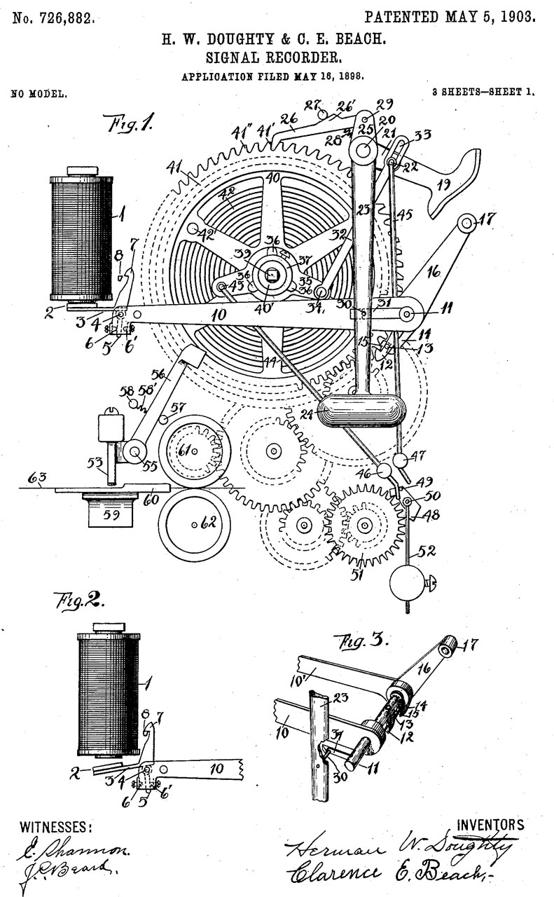
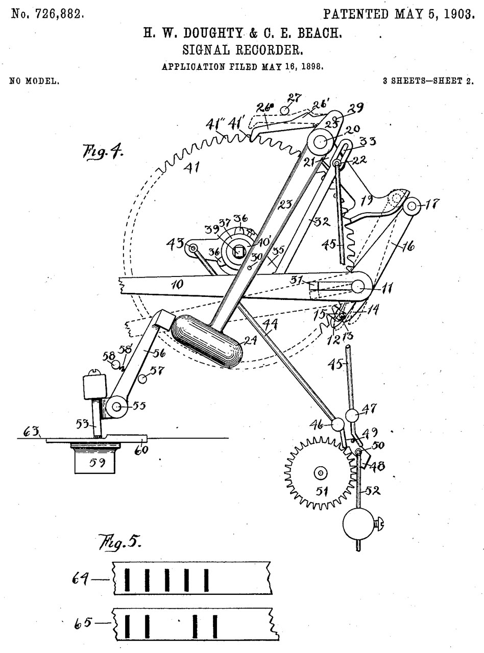
726882 Signal-recorder, Herman W Doughty, Clarence E Beach, Star Electric Co.,1903-05-05 - spring motor, released by electromagnet w/electromagnet for pen
GB190614607 Guards for Door Keys of Fire Alarm Boxes and the like, Joseph Woodman Stover, Frederick William Cole, 1906,
758724 Signaling System, J. Weatherby, Weatherby Electric and Manf Co, Jr. May 3, 1904 - district telegraph, operates even with cut line
808087 Electric Signaling Apparatus Circuit, F.B. Herzog, E.P. Hopkins & C. Herrmann, Dec 26, 1905 - for use with: 289834, 315027
824804 Auxiliary fire-alarm system, G.F. Milliken, Gamewell Auxiliary Fire Alarm Co, July 3, 1906 - indicator for firemen to know number of inside alarm pull, removes local tap bell coils when alarm has been sent (otherwise the loop would see all the tap bell coil resistances).
888340 Electric bell-ringer, George Macloskie, GE, - for train bell
949699 Signal-Box, Herman W Doughty, Clarence E Beach, Star Electric Co., 1910-02-15 - uses 2 arms to follow code wheel with contacts between them.
970886 Fire and police telegraph system, Frederick W Cole, Gamewell Fire Alarm Telegraph Co., 1910-09-20 - call box includes telephone & code wheel (police & fire combined)
1065478 Repeating-transmitter for fire-alarm telegraph systems, Nathan H Suren, Gamewell Fire Alarm Telegraph, 1913-06-24, - call box
1077767 Auxiliarized fire-alarm box, Nathan H Suren, Gamewell Fire Alarm Telegraph Co.,1913-11-04 - a relay is added
1078985 Signaling system, Clarence E Beach, (assigned to George O. Knapp), 1913-11-18 - local alarm bell in addition to sending code to fire brigade
1079309 Signal-Box, Herman W Doughty, Clarence E Beach, (assigned to George O. Knapp), 1913-11-18 - non-interfering
1080246 Controlling system for signaling-circuits, Clarence E Beach, Herman W Doughty , 1913-12-02 - 3 groups of 3 series boxes (9 total)
1106072 Frangible covered guard, Clarence E Beach, 1914-08-04 - glass plate needs to be broken in order to sound alarm
1120459 Condition-indicating mechanism for signaling systems, Herman W Doughty, 1914-12-08 - to monitor the fire alarm box circuit
1120995 Signaling system, Clarence E Beach, (assigned to George O. Knapp), 1914-12-15 -
RE14273 Signaling system, Clarence E Beach, Gamewell Fire Alarm Telegraph Co., Mar. 20, 1917 - the call box has a local switch that can add resistance into the circuit which in turn allows selecting to ring local only alarms (same building, floor or local fire dept.).1205319 Signal-box, Clarence E Beach, Lee J Voorhees, Gamewell Fire Alarm Telegraph Co., 1916-11-21 - "For Fire Open Door - Pull Handle Way Down"
1207838 Non-interference signal-box, Clarence E Beach, Lee J Voorhees, Gamewell Fire Alarm Telegraph Co., 1916-12-12 - more sensitive, lower power consumption
1225934 Fire-alarm system, David G Dee, R.H. Rogers, 1917-05-15 - code wheel system on magneto phone line
1237234 Variable-signal transmitter, Clarence E Beach, Herman W Doughty , 1917-08-14 - programmable 2 digits with appropriate spacing between digits and the group of digirts
1240811 Signaling mechanism, Clarence E Beach, Gamewell Fire Alarm Telegraph Co.,1917-09-25 - major patent, parts subdivided - different classes of signal on same circuit, police, combined telegraphic and telephonic,
1244587 Successive non-interference signal-box, Frederick W Cole, Gamewell Fire Alarm Telegraph Co., 1917-10-30
1294053 Electric Switch, Frederick W Cole, Game Well Fire Alarm Telegraph Co., 1919-02-11, 200/535; 200/241 -
The switch contacts in the "Three Fold" mechanism are made this way.
1266920 Signal-box having local alarm, Frederick W Cole, Gamewell Fire Alarm Telegraph Co., 1918-05-21 - T-handle outside box, on keyless-door box
1274367 Signal System, Clarence E Beach, Gamewell Fire Alarm Telegraph Co.,1918-08-06 - superimposing normal telegraph signals with alarm signals
Improvements on:1345355 Signal-recorder, Herman W Doughty, Gamewell Fire Alarm Telegraph Co., 1920-07-06 - multichannel pen recorder
1176421 Magnetic Device, Clarence E Beach, 1916-03-21 - polar relay
1176422 Magnetic Device, Clarence E Beach, 1916-03-21 - polar relay
1422523 Signaling mechanism, Clarence E Beach, Gamewell Fire Alarm Telegraph Co., 1922-07-11 -
1479608 Attachment for signal boxes, Jackson George Alfred, Gamewell Fire Alarm Telegraph Co., 1924-01-01, 340/287 -
"To Open Pull Handle . . For Fire Pull Lever" hinged door on front of box.
1627685 Signaling system, Clarence E Beach, Gamewell Corp, 1927-05-10 - "normal" (maintenance) signals treated differently from "emergency" (fire) signals
1986026 Signal transmitter, Nathan H Suren, Harry S Smith, Gamewell Co,1935-01-01 - 14 pages of drawings, to generate non-interference & Succession codes
1998436 Signal system, Clarence E Beach, Gamewell Corp, Filed: 1932-01-20, Pub: 1935-04-23 - "... the new circuit operates successfully with boxes having non-interference and succession effects, with short circuits bridging any number of boxes and not only under the faulty conditions which have been expressly discussed but also under more or less similar troubles or combinations thereof."
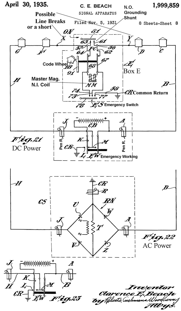
1999859 Signal apparatus, Clarence E Beach, Gamewell Corp, Filed: 1931-11-05, Pub: 1935-04-30, 340/295; 340/292 -
This patent covers a much improved system that includes:
1. Perfect non interfering operation, i.e. two boxes can be triggered at the same time
2. Either loop wire H or B can be cut or grounded or a short can develop between H & B
2270925 Signal apparatus, Frank R Bridges, Gamewell Corp, 1942-01-27 - does not allow spring to run down when there is a interfering box that has control of the line
RE22514 Signal apparatus, , Frank R Bridges, Gamewell Corp, July 11, 1944 - does not allow spring to run down when there is a interfering box that has control of the line
2300402 Signaling system, Clarence E Beach, Filed: 1940-08-03, Pub: 1942-11-03 - path to fire, or path away from danger
2301924 Circuit controller for signaling means, Clarence E Beach, Priority:1940-02-19, Pub: 942-11-17, - specially suited for embodiment in sub-stations of so-called auxiliary fire alarm systems
3214748 Fire alarm apparatus and systems, Donald J Brown , Filed: 1959-01-28, Pub: 1965-10-26 - improvement on 1999859 - This patent shows 3 electromagnet coils (Fig 9), so not applicable to this street box.
"As is well known, a municipal fire alarm circuit normally consists of a series electrical circuit or loop extending from one side of a D.C. power source, located at a central station with a recorder and alarm, through a plurality of signal boxes located throughout the municipality in series and back to the other side of the central office power source. Normally a maximum of 40 boxes are connected to any one loop. Each box is provided with a shunt switch which is normally connected in series in the loop circuit and which is closed until the box is pulled for the purpose of transmitting a fire alarm. In addition each box also contains a pair of can actuated signalling contacts connected in parallel with the shunt switch. Until the box is pulled, the signalling contacts are shunted by the box shunt switch. When the box is pulled and the box shunt switch opened, the signalling contacts are connected in series in the circuit loop to the central station power source. Under normal conditions when a box is pulled, cam actuation of the signalling contacts will transmit a coded signal in the form of a series of circuit interruptions to the central station to actuate the alarm and recorder. Boxes are normally arranged so that if one box in the circuit has been pulled and is transmitting, the pulling of a second box in the same circuit will not interfere with the transmission of the signal by the first pulled box and signal transmission by the second pulled box will be delayed until the completion of the signalling cycle of the first box. This is known as non-interfering succession operation of a fire alarm box.4401978 Combination detector, Elias E. Solomon , Gamewell Corp, Aug 30, 1983 - Ionization combined with smoke detector
In addition and as a further safety measure, some boxes are designed to detect a break in the series loop circuit to the central station, to automatically establish a ground at the box when the box is pulled and a circuit break is detected, and to transmit a signal to the central station through ground and over the unbroken portion of the loop circuit after a ground has been established at the central station. In all but the most complicated known boxes of this type, a part of the normal series of signal groups is lost because the transmitting box begins to transmit as soon as the auxiliary circuit is established and stops at the end of the cycle in which the ground was established. Also the establishment of the central station ground heretofore has generally been effected manually with resultant loss of at least a further portion and possibly all of the alarm signal from the self grounded transmitting box because the known self grounding central station systems have had no automatic system for removal of the ground following repair of the circuit break. It is also important in order to prevent loss of signals that the box also operate non-interfering Succession over the auxiliary line as well as over the normal line. Otherwise, if a box has been pulled and is signalling in the half of the loop between the break and the central station in which a Second box is pulled, the pulling of the Second box will either mutilate the signal of the first pulled box as the result of two transmitters operating simultaneously over the same channel or have its own signal lost in whole or in part as a result of the ground on the transmitting box depending upon whether it is between the central station and the first pulled box or the first pulled box is between the central station and the second pulled box. While fire alarm signalling boxes heretofore known have operated non-interfering succession over the normal circuit they have not operated non-interfering succession over an emergency established ground or auxiliary line following detection of a circuit break.
Further, while from the point of view of transmitting a fire alarm to the fire station as rapidly as possible it is desirable to permit interconnection of local private fire alarm systems installed in buildings and the like with the municipal system, such interconnections are normally not permitted due to the frequency in which false fire alarms are transmitted as a result of circuit difficulties in the private system and when they are permitted, only mechani cal interconnection may be made to a standard type of fire alarm box electrically connected in the municipal cir cuit under the existing municipal regulations in this country. Even under these limitations however a power failure in the private circuit in prior systems will result in the transmission of a false fire alarm over the municipal System."
Traffic Lights
Looking for information on "Gamewell Flashlight Controller"
1908589 Time Relay, Durbin Vernon, Holtzer-Cabot Electric Co, 1933-05-9, 335/62; 968/805 -
2051369 Traffic control system, Durbin Vernon, Gamewell Corp, 1936-08-18, 340/923; 340/927; 340/941; 361/166; 361/202 -
2076396 Traffic signal, Blue Arthur Ayling, Gamewell Corp, 1937-04-06, 340/917 -
3047838 Traffic cycle length selector, Hendricks George Donald, Gamewell Corp, 1962-07-31 -
3049614 Traffic signal adapter, Willis M Eikenberry, Gamewell Corp, 1962-08-14 - for light bulbs
3072883 Traffic controllers employing static, logic control elements, Hendricks George Donald, Garland E Fieser, Gamewell Corp,
3075173 System of automatic offset control for traffic signals, Joseph N Paul, Gamewell Corp, 1963-01-22
3110880 Traffic actuated cycle lengths selector apparatus, Garland E Fieser, Frank W Hill, Gamewell Corp, 1963-11-12
3120651 Traffic adjusted traffic control systems, Hendricks George Donald, Gamewell Corp, 1964-02-04
Diaphone Air Horn
Wiki: Diaphone -
YouTube:
Web.archive: The History of the Diaphone - The Diaphone Fog Signal - Gamewell Diaphone Technical Info - Diaphone Restoration (missing photos) -
Note that when analyzing the Helmholtz acoustic resonator (Wiki) the model is a "piston" of air moving back and forth. Also see my web page:
Tuning Forks & Helmholtz Resonators -
Gamewell Diaphone Horn (Fire Horn) 5:17 - Working Animation of the Gamewell Diaphone 1:37 - Saltaire Volunteer Fire Company's Gamewell Diaphone Horn Test - How The Historic SF Foghorn Works 14:04 - The Gamewell Diaphone, 15:42 (72 CFM) - Bronx Diaphone Bench Test (0:12) no horn -Gamewell Diaphone and Kahlenberg horns (1:05 on pickup truck) - Kahlenberg Ship Horns in Western Mass (1:54) -All Horn Sounds (As of Now) 6:09) -
Foghorn at East Brother Light Station Sounds Out Over San Francisco Bay, 3:48 -
lizard Lighthouse, "Sounding" for fog. 1997, 2:20 -
Very rare Lighthouse Diaphone Type CC (bigmikesocal), 1:15 -
Double acting steam engines (Wiki) can push and pull depending on which side of the piston the steam pressure is applied (controlled by the valving). I think the piston in the Diaphone has the air valved so that it both pushes and pulls the piston rather than use a spring and a single acting system.
YouTube: How a Type F Diaphone Fog Horn Works, 4:59 - HEAR a Type F Diaphone and Type B Diaphone Side by Side, 0:26 -
702557 Sound-producing device suitable for sirens, &c., Robert Hope-Jones, June 17, 1902, 116/147 - common piston configuration.
736428 Sound-producing device suitable for sirens or like instruments, J.P. Northey, Aug. 18, 1903, 116/147 - separate air supplies for piston (high pressure) and noise making (low pressure)
864909 Sound-producing device, J.P. Northey, Sept. 3, 1907, 340/404.1; 116/147 - electromagnet drives piston-air valve back and forth
879190 Sound-producing device, John Pell Northey, Feb. 18, 1906, 116/147 - separate air paths inside device for piston and sound production
973960 Sound-producing device, J.P. Northey, Oct. 25, 1910 - back to back dual reasonators
976682 Sound-producing device, John Pell Northey, Nov. 22, 1910 -
1016087 Sound-producing device, John Pell Northey, Jan. 30, 1912 - Dual tone Fog Horn - Gamewell's Diaphones were strictly single tone
1175656 Sound-producing device for fog-signaling, position-locating, or the like, John Pell Northey , DIAPHONE SIGNAL Co
1202305 Sound-producing device for fog-signaling, position-locating, and the like, John Pell Northey , DIAPHONE SIGNAL Co, 1916-10-24, -
1619585 Sound-signaling installation, Northey John Pell, Mar. 1, 1927 - uses two storage tanks, one high pressure and one low pressure - reducing the storage requirement.
1799387 Sound-producing device, John P Northey, 1931-04-07, - re 736428: "In the present invention I have provided a construction in which the hollow p. and its cylinder share in the control of the driving air to provide supplemental and more direct exhaust from behind the piston head, and also to provide supplemental and more direct exhaust from behind the piston head, and also to provice supplemental air passages from the inlet t the back of the piston head."
1799387 Sound-producing device, John P Northey, March 1, 1929 - "...lower pressure may be employed to actuate the piston"
1844226 Sound-producing device, Rodney V Northey, March 31, 1931, 116/147 - changing air pressure can change note to normal or an octave lower.
1979048 Sound producing apparatus, Rodney V Northey, 1934-10-30, - "In the present invention the problem is to produce a sound producing device particularly adapted for use on railway locomotives on which, for certain reasons, it is desirable to use compressed air to vibrate the piston and steam from the locomotive boiler to produce the sound. "
The following patent is a major upgrade to the classic diaphone horn.
2854944 Fog horn, George J Thiessen, National Research Council of Canada, 1958-10-07, - "The diaphone fog horn was widely adopted as the standard fog horn signalling device about forty years ago and has been little modified in that period. It is a sturdy and reliable instrument, but its practical operating efficiency is extremely low. Occasionally in isolated in stances, fog horns may be found to operate with efficiencies as high as 5%, but operating conditions are so unstable that one can only rely on a value of efficiency of the order of one-half of one percent." ... "Existing diaphone type fog horns have unsatisfactory frequency stability. Measurements taken on five different horns in service, each having a nominal frequency of 180 cycles per second, gave frequencies of 206, 196, 192, 243 and 184 C. P. S. respectively when blown at 30 p.s. i. air pressure. When the piston of the last fog horn was removed, oiled and then replaced, it gave a frequency of 199 C. P. S. initially, but gradually drifted back to 187 C. P. S. after 50 seconds of actual blowing." ... "According to the present invention, the frequency stability of the fog horn is improved by reducing the mechanical impedance of the piston in the diaphone as an oscillating mass, while maintaining as high as possible the mechanical impedance of the throat of the horn. When the piston impedance is low enough in relation to the throat impedance, the horn will dominate the system and it will then tend to take charge of the piston and control the oscillation thereof."Other Loud Sound makers
Wallace & Tiernan
I have a web page about their altimeters & Barometers.
2222218 Synchronous selector apparatus, Charles F Wallace, Wallace and Tiernan Inc, 1940-11-19, - radio control, maybe for buoys
2306819 Sound signal apparatus, John R Mackay, Wallace and Tiernan Inc, 1942-12-29, - electromagnet directly drives diaphragm
2306820 Sound signal apparatus, John R Mackay, Wallace and Tiernan Inc, 1942-12-29, - electromagnet directly drives diaphragm
2340604 Sound signal apparatus, John R Mackay, Wallace and Tiernan Inc, 1944-02-01, - electromagnet directly drives diaphragm, amplitude adjustment, for use on a buoy
2342085 Signal device, John R Mackay, Wallace and Tiernan Inc, 1944-02-15, - burned out lamp replacement, maybe for lighthouse
3138795 Electronic audible horn, Charles F Wallace, Norman S Creswick, Watters Bill Gene, Wallace and Tiernan Inc, 1964-06-23, - cites 12 patents, for use on a buoy
3292571 Audible signal apparatus, Watters Bill Gene, Wallace and Tiernan Inc, 1966-12-20, - for use on a buoy
Federal Thunderbolt
In NBS Publication LC-685 where they tested a number of proposed air raid warning devices, including a Diaphone model B, the Federal Thunderbolt was also tested.
1323826 Siren, O.S. Burke, Federal Sign System, Dec 2, 1919, 116/147; 340/404.2 - I think the basis of the Thunderbolt and emergency vehicle sirens. A later patent 1490313 attempted to allow the use of this siren in a fire alarm call box system by reversing the power to the motor to cause it to stop quicker than normal, but I suspect they were never able to get a siren to turn on and off quickly enough to work as fast as the Diaphone horn.
Tyfon pneumatic For Horn
Directions for Use, T75B (Fog Horn) & T75C (Fire Alarm Horn) (tyfon_type_t75bc_no.607.pdf)
1335921 Diaphragm-sounder and the like, Rydberg Helge Sven Albert, App: 1917-04-16, W.W.I, Pub: 1920-04-06, -
Svensson Fog Horn
1427034 Siren or Foghorn, O.H. Svensson, Aug 22, 1922, 116/139 - This is a hand cranked device with 3 piston air pumps
Lathrop Fog Horn
680874 Fog Horn, Llewellyn D. Lathrop, Aug 20, 1901, 116/139 - lever, bellows used to supply air to a horn. Made by Mason & Curtis.
Schwarze Electric (Faraday Electric Corp) pneumatic Fog Horn
Inspired by: What's this Mystery Item: @6:44 - Boat fog horn operated by large bicycle air pump: Faraday Electric Corp, Type H7, Hand Operated Ship's Fog Horn (Trafficaire)
Signal Corps. U.S. Army, Alarm MX-251/PN, Faraday Electric Corp, Adrian, MIchigan U.S.A.
1386804 Horn, Herman R Saxon, Carl J Schwarze, Schwarze Electric Co, Willys Corp, 1921-08-09, - motorized horn for Willys Overland (Wiki)
1888684 Signaling, Leslie H Middleton, Schwarze Electric Co (Faraday Electric Corp), 1932-11-22, - (Trafficaire)
2039694 Diaphragm horn, Voigtlander Frederick Von, Schwarze Electric Co, 1936-05-05, - (Trafficaire) -
2060911 Sound signaling, Voigtlander Frederick Von, Schwarze Electric Co, 1936-11-17, - double diaphragm klaxton horn
2074875 Synthetic tone signal, Voigtlander Frederick Von, Schwarze Electric Co, 1937-03-23, - dual electromagnets & diaphragms
2126433 Chime signal, Voigtlander Frederick Von, Schwarze Electric Co, 1938-08-09, - tubular gong struck by electromagnet (doorbell?)
2158209 Sound signaling, Voigtlander Frederick Von, Schwarze Electric Co, 1939-05-16, - right angle & spiraled car horn
2216380 Electromagnetic horn, Voigtlander Frederick Von, Schwarze Electric Co, 1940-10-01, - dual diaphragms
Danforth Falcon Air/Fog Horn
2840032 Portable Signalling Device, C.E.G. Reeves, Falcon Alarm Co, June 24, 1958, 116/112; 116/DIG.44; 116/137R; 116/142FP -
RE24730 Portable Signalling Device, C.E.G. Reeves, Falcon Alarm Co, Oct 27, 1959, 116/112; D10/120 - designed to be used with compressed air tank (maybe like W.W.II aircraft oxygen tank?) uses dichlorodifluoromethane (Freon-2)
Klaxon car Horn (Wiki) aka: Ah-oo-gh, Ahooga
I had one of these painted yellow, probably from my uncle who had Caterpillar tractors, and it had a plunger to spin the internal disk. It took a lot of force to get started, but then was easier. Made the classic ahoooga sound.
923048 Mechanically-actuated acoustic apparatus and method, M.R. Hutchison, May 25, 1909, 116/59; 116/142R; 340/390.1 - disk with protrusions its anvil mounted at center of diaphragm. - Klaxon
923049 Cam-operated horn, Miller Reese Hutchison, May 25, 1909, 116/59; 116/144 - Klaxon
923122 Mechanically-actuated diaphragm horn or alarm, Miller Reese Hutchison, May 25, 1909
956898 Signaling-horn, &c., Miller Reese Hutchison, May 3, 1910, 340/387.1; 5/164.1; 116/142R; 340/388.7 - Electromagnetic buzzer drives diaphragm with horn -
1050239 Electromagnetically-operated sounder, Carl J Schwarze, 1913-01-14, - electromagnets, not motor
1092117 Electromagnetically-operated sounder, Carl J Schwarze, 1914-03-31, - electromagnets, not motor
1111463 Horn and similar instrument, 340/388.4; 116/142R
1167601 Electromagnetically-operated sounder, Carl J Schwarze, Schwarze Electric Co, 1916-01-11, -
1240156 Signal, William Sparks-Withington (Sparton), 1917-09-11, 340/390.2; 116/144; 335/228; 335/256; 335/261; D10/120 - electric motor (?and manual plunger?)
American Bosch Magneto Corp Horn
1608218 Signal Horn, Ludwig P Kongsted, Ambac International Corp, Nov 23, 1926 - electromagnet based
Long Range Acoustic Devices (LRAD)
These speakers mainly transmit intelligible voice over great distances which classic megaphones (Wiki) can not. If you have been at an event, like a drag race, where the loudspeakers can be understood when you are close to a speaker, but not when you are far from a speaker while the sound is strong it can not be understood because it garbled.
Genasys - a variety of products for mass notification."
7729498 Modulator processing for a parametric speaker system, Michael E. Spencer, James J. Croft, III, Joseph O. Norris, Turtle Beach Corp (LRAD Corp), 2010-06-01, - "This invention relates to parametric loudspeakers which utilize the non-linearity of air when excited by high frequency or ultrasonic waves for reproducing frequencies in the audible range. In particular, this invention relates to signal processing and modulators for parametric loudspeakers." Also see: Ultrasonics - Holosonics audio Spotlight
9693148 Acoustic hailing device, Hernan Lopez, Genasys (LRAD Corp), 2017-06-27, - allow both warning siren and voice notifications.
Bells & Gongs
The difference between a bell (Wiki) and a gong (Wiki) escapes me. The Fire House Gong works in a way similar to a Ship's Bell in that the number of rings is important. This is very different from the bell associated with a bank burglar alarm where the bell rings continuously and there's no expectation that anyone would be counting the number of strikes. "Single Strike Bell" is a term I came across but even though the title of a product contains the words "Single Strike Bell" there was no mention of that in the description or data sheet. As of 2019 March 9 it's still a mystery.
There seem to be two types of single strike gong bells. There is the "Turtle Gong" which contains a mainspring very much like a wind-up clock that delivers the power and there is the electromechanical gong where the energy for the striker comes from an electromagnet. The Turtle Gong is said to be louder, but I think it's main advantage is the electromagnet that's used to release the mainspring is much more sensitive than the more powerful electromagnet used in the latter type.
Note if the clapper were to hit the bell/gong and stay on it there would be no ringing. The resonate frequency of most bells/gongs is in the audio range (most near 1,000 Hz) so the time when the clapper is touching the bell/gong should be extremely short [< 1/(10* frequency)].
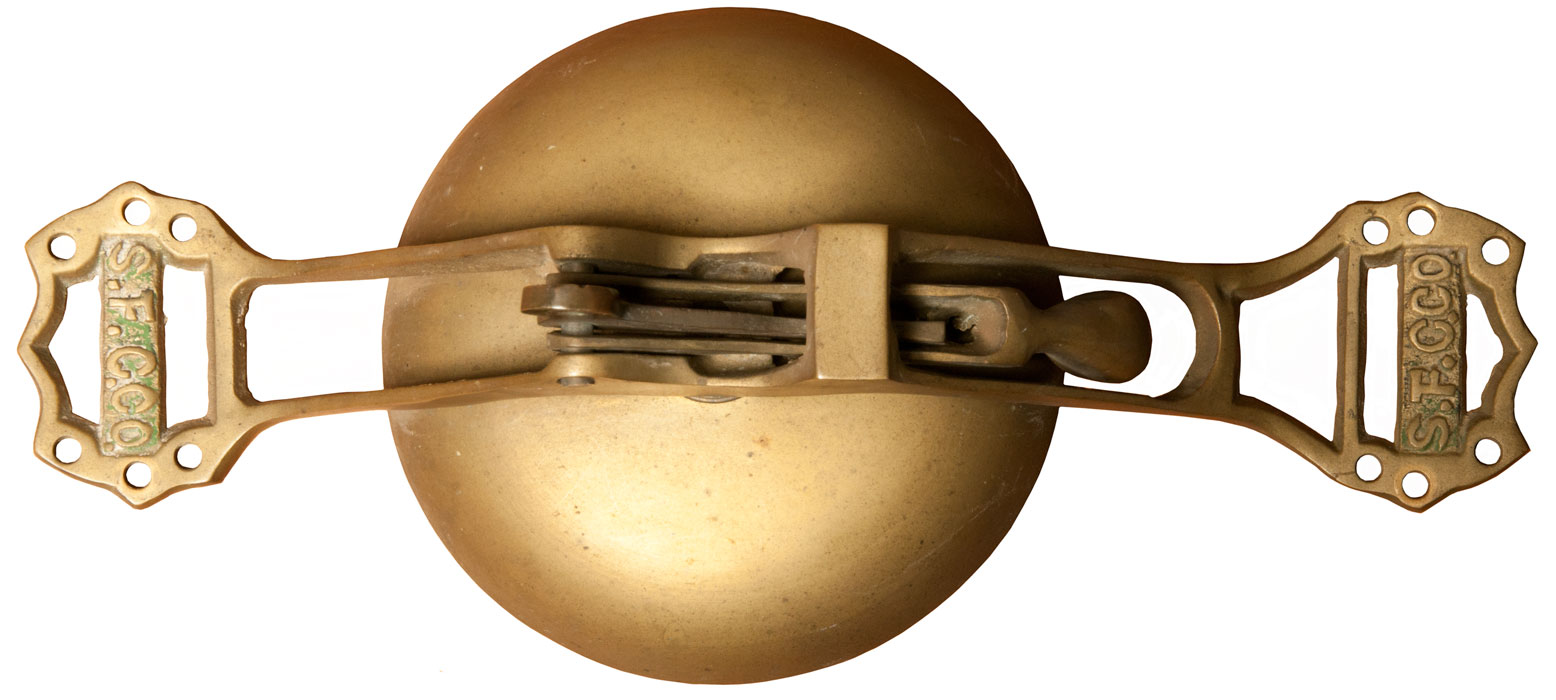
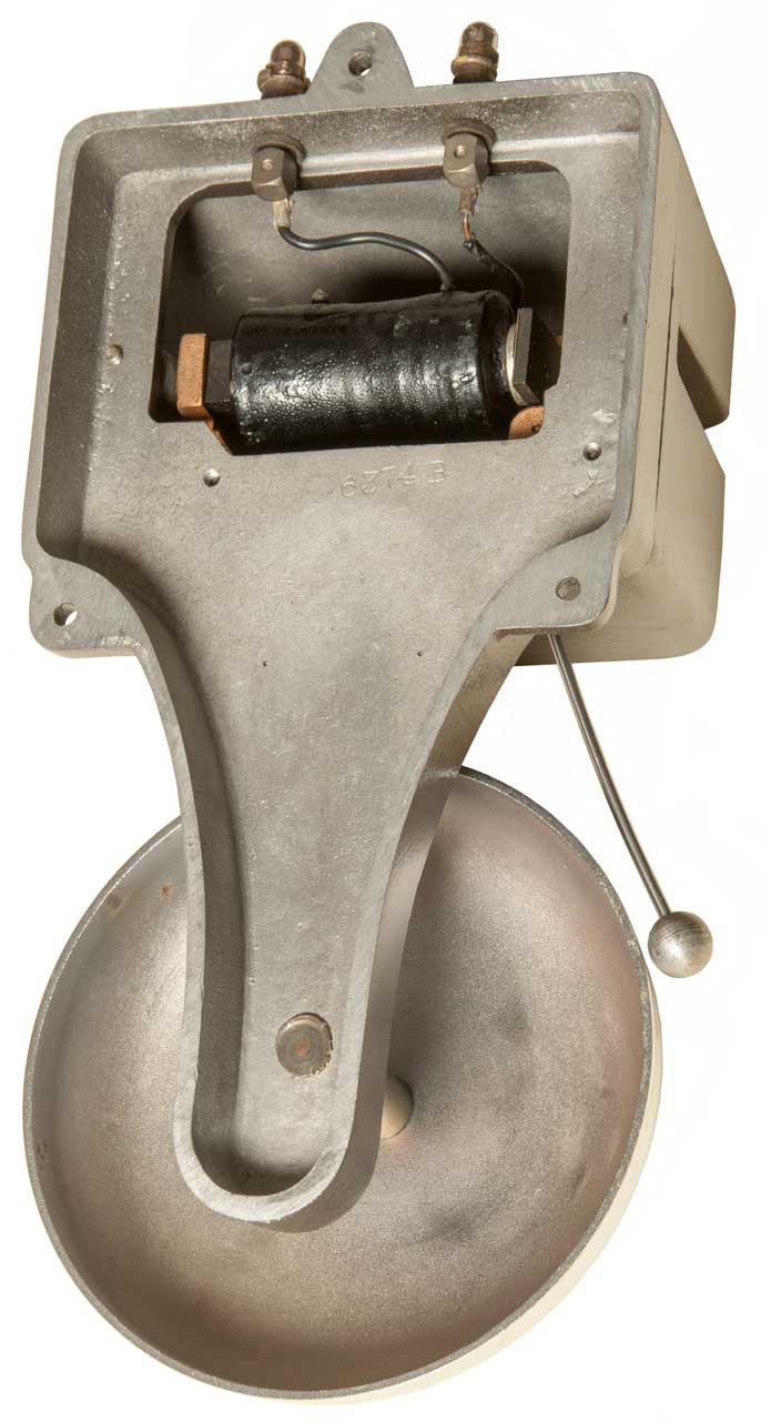
San Francisco Cable Car Co. Bell
While looking for bells and gongs I came across this one. Since I'm from San Francisco I got it. There are traces of green paint on the outside of the frame. I think this is a real S.F. Cable Car Co. Bell, not a reproduction. Note that there are two parts to the Clapper mechanism. That's to say the part with the hole for the pull rope is separate from the clapper. There may be a problem in that when the bell is mounted as shown in Fig 2 below gravity causes the clapper to rest on the bell. This can not be the case in use because the clapper would damp out the ringing after the strike. Fig 3 shows the bell in a position were gravity keeps the clapper free of the bell allowing it to ring for some time after each strike. Note: The bell was mounted on the ceiling of the car, i.e. Fig 2 is upside down compared to how it should be mounted.
Photos
Fig 1
Fig 2 As it would be if outside roof mounted. Problem gravity causing clapper to rest on the bell. There may be a missing spring?
It turns out that the bell is shown upside down, it should be inverted for proper operation. Gravity must hold the hammer away from the gong.
Fig 3 Positioned so that gravity keeps the clapper away from the bell.
193876 Street-Car Bells, C. Keppler, Aug 7, 1877, 116/165 - This may be the best match. This bell has the notch on the clapper with a plain rope pull lever.
NOTE: The bell is mounted so that the clapper is held away from the gong!
Cable Car & Trolley Car Bell Patents
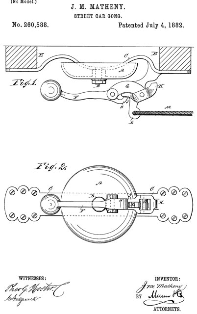
After getting the above Street-Car Gong this is a search to find a patent that covers it. 260588 is similar and explained the idea of preventing the clapper from being held against the bell if the conductor pulls and holds the rope. That would prevent the bell from ringing.
A Cable Car (Wiki) is powered by cable running underground. A Trolley Car (Wiki) is powered by an engine or motor.
San Francisco Cable Car System Bell Ringing Contest (Wiki). The bell used for the contest is different from this one. The contest bell is mounted outside on the roof with the bell like an umbrella, so when it rains the water will not collect in the bell. The clapper appears to be a single piece with a rope and cylindrical wooden handle. Note if this bell was outside roof mounted (Fig 2) the clapper would rest on the bell, not good.
Class Numbers
116 Signals & Indicators (single stroke bell 116/95; 116/148 Bells in general,
174 Electricity: Conductors & Insulators
340 Communications: Electrical (electric bell 340/392.1
Gong: see Bell
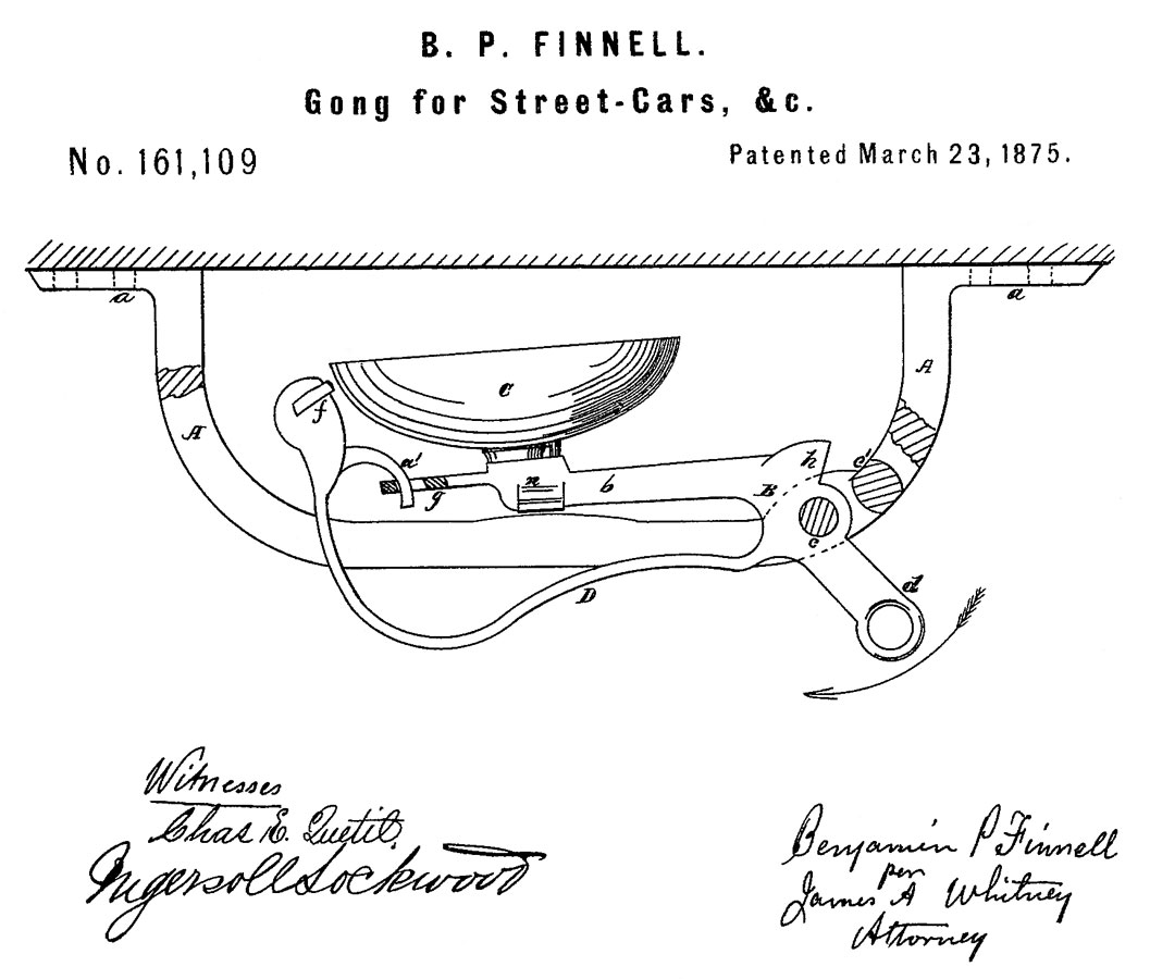
161109 Gong for Street-Cars, &c., B.P. Finnell, March 23, 1875, 116/165 -
The "elastic shaft" "D" is a silly idea. It's bound to break and before that the loudness will vary as the metal deforms.
169356 Gong for Street-Cars, W. Guilfoyle, Nov 2, 1875, 116/165 - both striker and bell move, the "elasticity" of the striker shaft is part of the design = N.G.
193876 Street-Car Bells, C. Keppler, Aug 7, 1877, 116/165 - very close to this bell.
245060 Street car gong, H.N.E. Cottier & J. Matheny, Aug 2, 1881, 116/165 - This looks very similar to my bell.
260588 Street-car gong, James M. Matheny of Woodstock, Illinois, July 4, 1882, 116/165 - "This lever (J) prevents the hammer head from being held against the gong by the strap or cord (M)." It works. also the Bolt that holds to gong to the frame is exposed so can easily be tightened if the need arises.
Note this is a single acting system, i.e. the rope runs horizontally in only one direction.
266964 Street-car gong, C.T. Brown, Nov 7, 1882, 116/165 - Double acting, i.e. two horizontal ropes running opposite directions.
271176 Gong for Street Cars, C.H. White, Jan 23, 1883, 116/165 - hammer is on hinged it's shaft, may require a hole in ceiling to clear hammer. Not better than prior designs. The stop C2 may be too weak to take a large number of blows.
284032 Street Car Bell, J.T. Marett, Halstead & Spencer, Aug 28, 1883, 116/165 - uses sliding bolt to prevent hammer from staying on bell
This has the feel of my bell, but it uses the bolt in the striker as the decoupling mechanism, so is not applicable here.
370602 Gong or bell for street-railway cars, J.A. Brill, Sept 27, 1887 - double or quad acting, uses flying plunger instead of lever J to keep bell ringing, seems complex.
436560 Electro-mechanical gong, G. Doyle, Sept 16, 1890 - power from wind-up spring, release by electromagnet
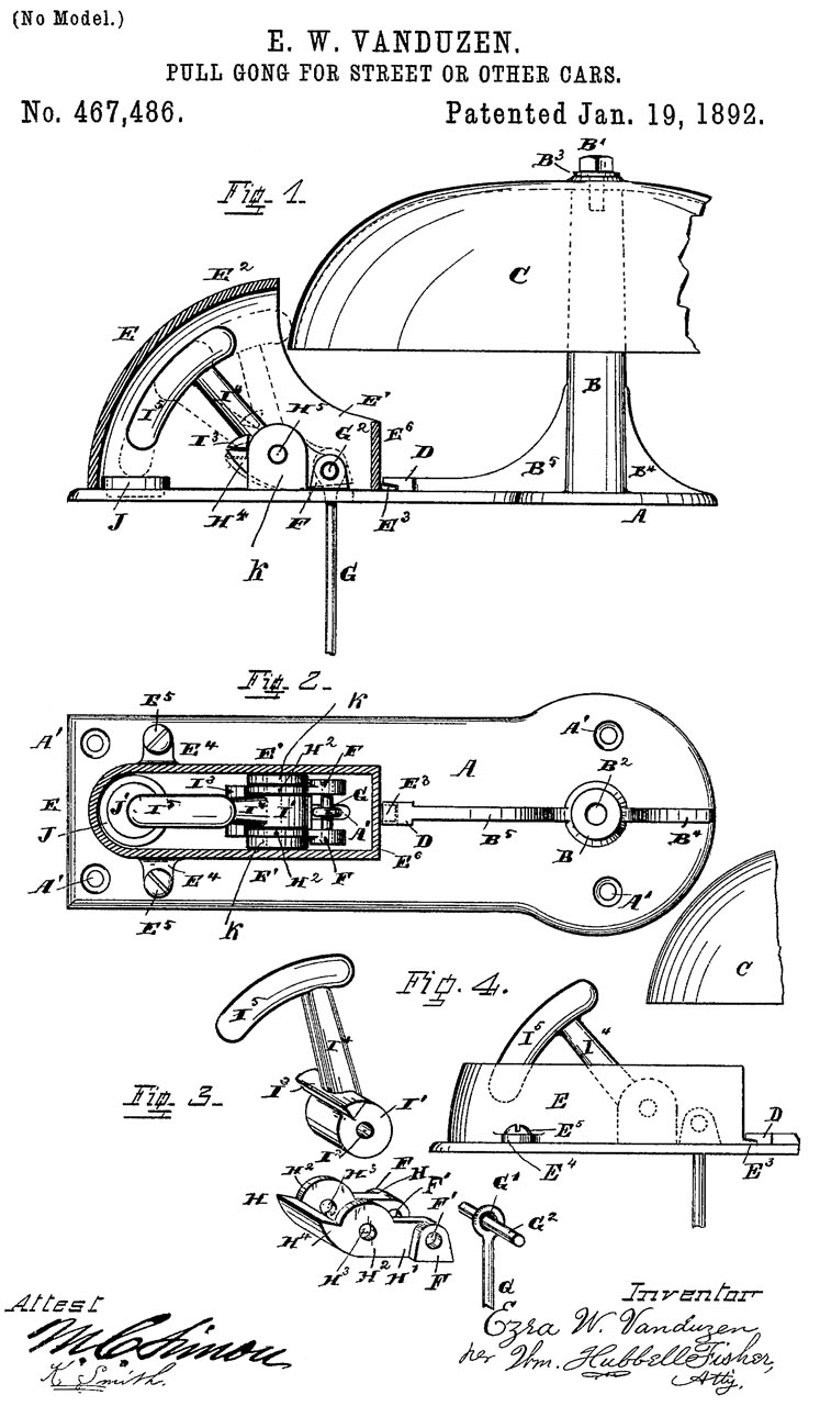
467486 Pull-gong for street or other cars, E.W. Vanduzen, Jan 19, 1892 - has the look and feel of the current gong on S.F. Cable Cars (as seen on YouTube coverage of the SF Cable Car Bell Ringing Contest). It mounts on the roof with the bell dome acting as an umbrella. Good for sound transmission. and the rope goes straight down, not horizontal. Contains mechanism to prevent hammer staying on bell.
573224 Actuating device for street-car gongs, T. Kelly, Dec 15, 1896, 116/60; 116/164 - foot pedal - not much fun.
Faraday antique Fire Alarm Products - faraday@cteksys.net sent an email but no answer.
24173 Gong or bell for signals, I.F. Woodward, 1859-05-24, 116/164 - "for Railroad-Cars, Steamboats, Hotels, &c." - maybe of the type where a lanyard is pulled tripping the striker
208275 Electrical Alarm-Striking Device, J.A. Swift, Sept 24, 1878, 340/398.1 - weight driven gong one strike per pulse on the electromagnet.
260588 Street-car gong, J.M. Matheny, July 4, 1882, 116/165 - "This lever J prevents the hammer head from being held against the gong by the strap or cord M."
292889 Call-Bell, A.W. Barton, Feb 5, 1884, 116/155 - like on store counter - press plunger down to ring.
293938 Electric Call Bell, D. Boyd, Domestic Electrical Mfg Co.,Feb 19, 1884, 340/393.2; 340/397.4 - has a couple of batteries mounted with bell on common base.
300253 Electric Bell, E.W. Hazazer, June 10, 1884, 340/387.1; 340/397.4 - looks very much like a common door bell, i.e. vibrating type,, not single strike.
318472 Electric Signal Bell, C. Henzel, May 26, 1885, 340/815.71 - includes an visual annunciator
331463 Electric signaling apparatus, J.P. Tirrell, Dec 1, 1885 - weight driven - for departure signals for railroad-trains. Uses notched tape.
345101 Gong Bell, E.C. Barton, July 6, 1886, 116/164 - "single stroke" like for boxing,
347634 Automatic Electric Signal, H.C. Nichlson, Aub 17, 1886 - similar to a clock escapement where an electromagnet moves the pendulum back and forth. Requires bipolar drive.
378124 Electro Magnetic Bell, J. & S. Wetzler, Feb 21, 1888, - bob on striker arm is adjustable along arm
389080 Electro-magnetic bell, W. Humans, American Magnetic Electric Co, Sept 4, 1888, - uses permanent magnet
393710 Electric Bell, A. Lungen, Nov 27, 1888, 340/392.1 - dual coil classic door bell, but with terminals on sides.
406294 Electric trembler-bell, J.F. McLaughlin, July 2, 1889 - Liberty bell shape with electromagnet clapper inside
451121 Electro mechanical gong striking machine, T.F. Gaynor, Gaynor Electric Co, Apr 28, 1891 -
461241 Gong or Bell, J.W. Grantland, Zimdars & Hunt, Oct 31, 1891 - pull chain turns disk with bumps which cause striker to hit bell.
461458 Automatic bell-sounding mechanism, E.W. Vanduzen, Oct 20, 1891 - weight driven mechanism rings church bell for fire alarm.
482983 Bell, E.S. Piper, Sept 20, 1892 - push down to ring like at hotel or shot to summon clerk.
483309 Electric Bell, N.H. Raynond, Sept 27, 1892 - common doorbell w/porcelain base
486354 Electro Magnetic Bell, J.J. Ross, Nov 15, 1892 - dual bells, quad coils, more reliable than prior art.
501292 Electric Bell, W.J. Newman, July 11, 1893 - progressive sheet metal forming
513587 Electro-mechanical device for bells, W.O. Meissner, Jan 30, 1894 - coil core is on center line of blot at center of bell.
519581 Alarm Bell, A.H. Langdon, May 8, 1894 - mechanical under dome, hand cranked
525145 Electromagnetic Call Bell, J.J. Geary, aug 28, 1894 - single coil, low cost
534330 Electric Bell, W.A. Harvey, Feb 19, 1895 - has the look of the common door bell but with single coil with it's axis plumb - i.e. to be cheap.
539431 Electric Bell, F.G. Ingersoll, Dewey Electronic Signal Co, May 21, 1895 - electromagnet under bell dome drives striker. for use on streetcars.
596085 Electrical signal-bell for street-cars, J.P. Orr & T.F. Galvin, Dec 28, 1897 - rings for a fixed number of strokes.
611794 Bell Ringing Mechanism, H.S. Ross, Oct 4, 1898 - manual gong
625923 Magneto Bell Striker, R. Brueckner, Holtzer-Cabot Elec. Co., May 30, 1899 - dual coil like telephone type
626131 Selective electric signal, Selective Electric Signal, J.A. Barrett, AT&T, May 30, 1899 - for party line telephone systems
637846 Electrical and selective signaling, J.A. Barrett, AT&T, Nov 28, 1899 - for party line telephone systems
646222 Dlectric Bell, F. & H.F. Keil, Mar 27, 1900 - Door Bell with two thumb nut terminals at bottom. easy to clean contacts.
717137 Electric signal-gong, Henry C Thomson, Electric Gas Lighting Co, Dec 30, 1902 - one clapper between bells, other clapper under one of the bells
723048 Electromagnetic bell-ringing mechanism, John J Sheahan, Mar 17, 1903 - aimed at larger musical bells
749365 Electric Bell, H.E. Dey, Jan 12 1904 - two gongs open fact to open fact, electromagnet on angle so each end strikes different gong.
757271 Electromechanical gong, Frederick W Cole, U.S. Fire and Police Telegraph Co, Apr 12, 1904, 340/398.2 -
824397 Electric Gong, William F Word, June 26, 1906, 340/392.1 - striker w/adjustable spring that holds it away from gong
868221 Mechanism for gongs, &c., H.E. Reeve, Oct 15, 1907 - spring would clock work provides strike power, electromagnet trips striker, continuous ringing
871168 Electric Bell, H.J. Heeny, Holtzer Cabot Elec. Co., Nov 19, 1907 - outdoor use on ship
872145 Protective Shield for Skeleton Frame Bells, G.L. Patterson, Nov 26, 1907, 340/387.1 -
872146 Adjustment for Contacts, G.L. Patterson, Nov 26, 1907, 340/392.1 -
866471 Electric Bell, R.L. Hunter, Sept 17, 1907 - vibratory using solenoid.
913104 Undulating-current apparatus, Fred Cedergren,
925439 Gong-striking mechanism, H.E. Reeve, June 15, 1909 - spring wound clock work provides strike power, electromagnet trips striker with soft striker stop.
956898 Signaling-horn, &c., Miller Reese Hutchison,1910-05-03 - buzzer driving a horn for cars
1054379 Electric-bell mechanism, George B Wurster, W.R. Ostrander & Co, Feb 25, 1913, 340/392.1 - hinged striker arm
1091548 Electromagnetic bell, Eugene W Vogel, Railroad Supply Co, Mar 31, 1914, - for railroad crossing
1116537 signal Receiver, C.A. Bals, Nov 10, 1914, dual bell, dual coil looks like telephone?
1123818 Electric Bell,Frank S Tucker, 1915-01-05 - lower cost striker.
1125489 Electromagnet structure, William W Dean, Curtis B Camp, 1915-01-19 - similar to dual bell used in telephones.
1155869 Gong, C.E. Avery, Manhattan Electrical Supply Co (MESCO) Oct 5, 1915 - improved escapement
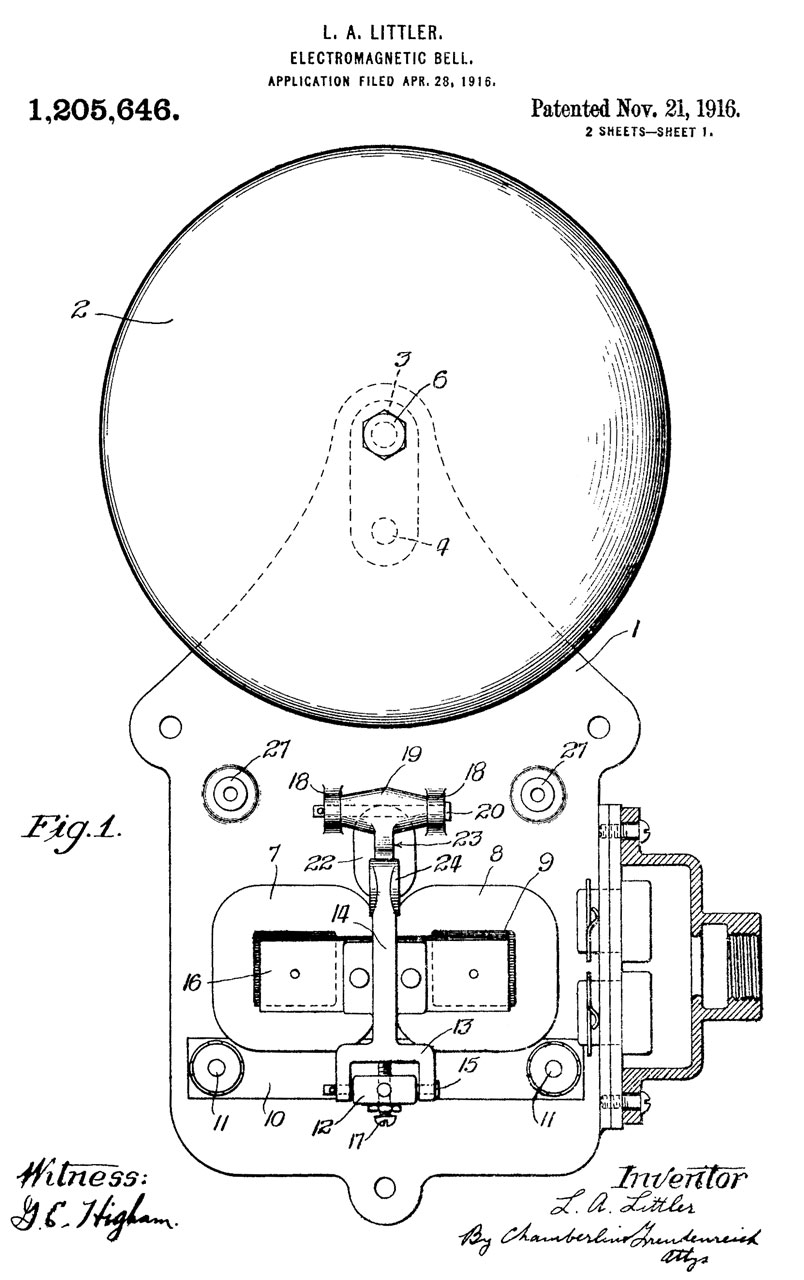
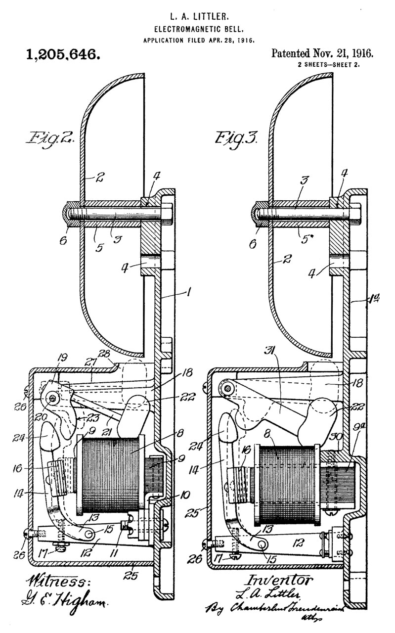
1205646 Electromagnetic bell, Lewis A Littler, Autocall Co, Nov 21, 1916, 340/392.1 - electro-magnetic bell using a minimum of current. two stage strike, no mechanical winding, heavy hammer very different from light weight clapper.
1236117 Signal Bell, L.C. Smith, 7 Aug 1917, 116/165 - manual operation by pulling rope. railway cars.
1216743 Electric bell, William J Smith, Edwards and Co., Feb 20, 1917 340/397.3 - plunger (rod) hits edge of gong/bell.
works with either AC or DC.
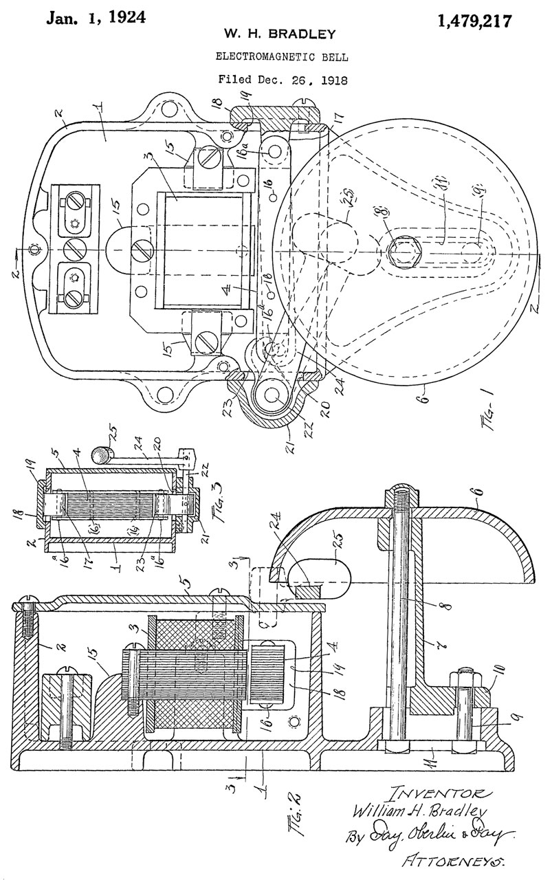
1479217 Electromagnetic bell, William H Bradley, Autocall Co., Jan 1, 1924, 340/387.1; 340/396.1 - shaft and swing arm striker.
1500325 Self-Winding Gong, W.H. Kallenbach et al, July 8, 1924, 340/398.3 - I think similar to a Self Winding Clock.
1633583 Electric Bell, William F Hendry, Manhattan Electrical Supply Co (MESCO), June 28, 1927 -
1664933 Signal instrument, King George Ernest, Gamewell Corp, 1928-04-03, - paper tape printer/punch
1674245 Electric Bell, A.C. Gaynor, E.G. Gaynor, June 19, 1928 - doorbell, more sheet metal
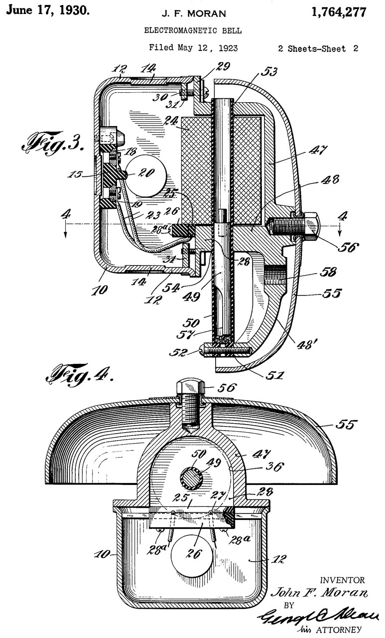
1764277 Electromagnetic bell, John F Moran, June 17, 1930, 340/401.1; 340/328 - Solenoid fires plunger at inside of gong/bell
Faraday 4070?
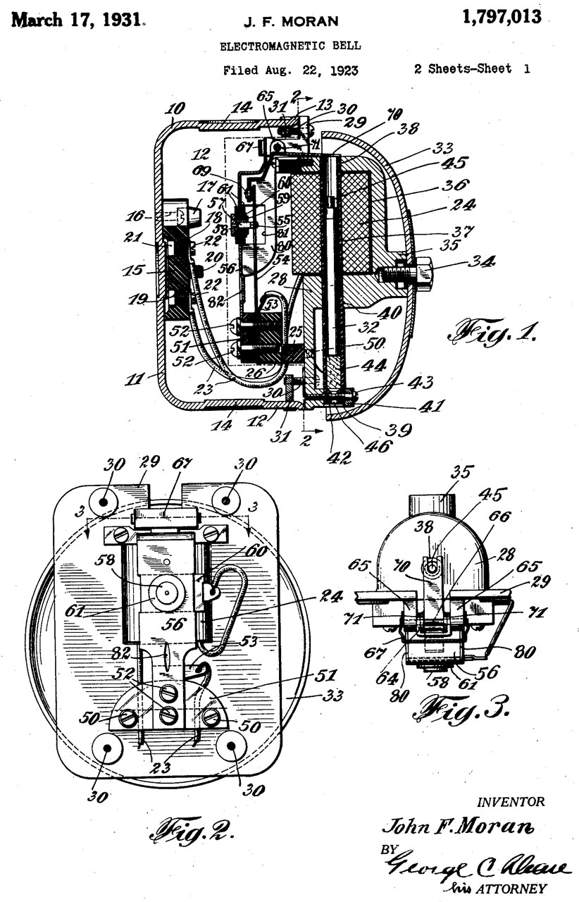
1797013 Electromagnetic bell, John F Moran,Mar 17, 1931, 340/397.4; 174/520 - solenoid and plunger type,Buzzer operation by adding parts to single stroke version. The tip of plunger hits lever that throws switch.
1819843 Electromagnetic bell, Louis E Richmond, Autocall Co., Aug 18, 1931, 340/392.1 - striker rod is sheet metal tube with striker tip.
Page 1
page 3
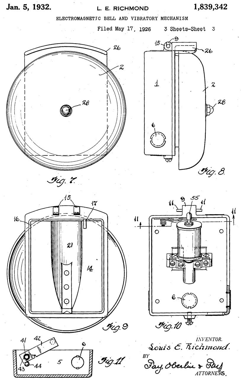
1839342 Electromagnetic bell and vibratory mechanism, Louis E Richmond, Autocall Co.,Jan 5, 1932, 340/392.1; 340/401.1 - Plunger not at an angle for vibratory action.
Return spring added.
1942811 Single stroke gong, Irving W Green, AT&T Corp, 1934-01-0, 340/397.1; 178/69.6; 340/328; 381/396 - for telephone service
1958964 Electric Bell, N. Franco, Aug 5, 1931 - Door Bell type but longer solenoid power time for stronger stroke
1962926 Electric Gong, Edward J Deary , Automatic Fire Alarm Co,
2099929 Electromagnetic bell, Joseph F Ebert, Signal Eng & Mfg Co., Nov 23, 1937 - very similar to Autocall 1797013 - makes it very easy to add parts to get vibratory operation.
2360666 Electric signaling apparatus, G.R. Fish, Edwards and Co, Oct 17, 1944 - AC or DC slow signaling - solenoid
2418863 Alternating current electric bell, Frank G Barber, 1947-04-15 - transformer-less, i.e. runs on house mains voltage (a very bad idea)
2432742 Alarm Bell, A.W. Fruh, Dec 16, 1947 - Electromagnet under bell, low friction rod striker
2443559 Mechanically Operated Bell, F.T. Garceau, Aug 9, 1946 - factory use, but has the look of a boxing match bell.
2476055 Warning bell device, Magdelain Philippe , Reeve Electrical Co, June 7, 1946 - motor drives plunger = paced rings, not vibratory and not single stroke. TO work in noisy factory.
2522664 Electric bell with momentum action gong striker, Coleman Maurice, Sept 19, 1950, 340/392.1 -
Calls:2524320 Electromagnetic bell striker, Louis C King, Oct 3, 1950 - includes condenser, for railroad crossings, very loud
824397 see above
1054379 see above
1764277 see above
2360666 see above
2733435 Sound Output Control for Telephone Ringers, H.A. Bredehoft, Bell Telephone Labs, Jan 31, 1956 340/379 -
1233989 Percussion sounding device
1342543 Sound-regulator for audible signals - control for ringer loudness
2468474 Sound regulator for telephone ringers
3043995 Bipolar reciprocating alternating current bell motor, Joseph L Cassell, The Reeve Electrical Co, July 10, 1862 -
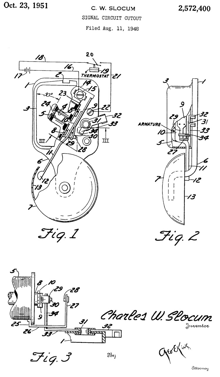
2572400 Signal circuit cutout, Charles W Slocum, Sperti Faraday Inc, 1951-10-23, 340/328; 340/327; 310/32 - Single Gong Bell with mechanism at 30 deg. angle so that there is room for the manual cutout (off switch). Mfg includes Sperti & Faraday.
Sperti also made Ultra Violet and Infra-Red Sun Lamps.
3139565 Electromagnetic bell striker actuating assembly, Walter E Levine, Edwards Co, June 30, 1964 -
3162850 Alternating Current Bell, F.E. Weld, Sept 21, 1961 - no contacts, frequency lower than 60 Hz.
3298020 Electric bell with momentum action striker, Malin Jack, Protective Alarm Devices Mfg Co, Jan 10, 1967, 340/396.1; 310/32 -
Calls:3325578 Cow Bell Instrument, D.M. Park, Seeburg Corp, June 13, 1967 - one transistor circuit that makes cow bell sound.Wheelock Signals Inc, April 22, 1969 - under dome, molded plastic frame.
1206699 Relay, GE
1962926 see above
2522664 see above
3043995 see above
4183018 Motor driven type gong striking mechanism, Tadashi Ishii, Kobishi Electric Co Ltd, 1980-01-08 -
4306227 Motor actuated bell, Tadashi Ishii, Kobishi Electric Co Ltd, 1981-12-15, 340/392.2 -
Faraday 4070 Striker w/o Bell
This is a single stroke type unit. The label says:
Farady Inc. Tecumseh, Michigan, Listed Audible Signal Appliance 328M
Cat. No. 4070
Amps. 0.36 Volts 24 - 28
Hz DC (Note DC not AC)
stenciled on the side: 75 Db Min. See Instr. Sht. For Actual Db.
Inside the two black wires connect to the solenoid.
The red wires join and are connected to a diode (the positive must be connected to a red wire).
There is a 10k680 ZNR Metal Oxide Varistor (MOV) connected across the electromagnet - maybe 10mm dia, 10%, 68 Volts
Fig 1
Fig 2 the diode in series with red is inside shrink tube.
Screw below plunger allows (after loosening bottom lock screw) adjusting striker distance to bell.
Cat. No. MB-3 4" Bell
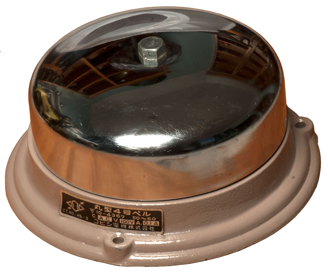
This is a single stroke bell. Catalog number MB-4, Model number 10-4367
Label says: 100 VAC 50/60 cycles (Japan mains voltage). Note no vibratory electrical contacts. The bell may have been dropped
since the solenoid seems bent down in Fig 2. The striker is almost, but not, touching the lower edge of the hole.
Fig 1 Chrome plated bell is a mirror.
Label in Japanese.
Fig 2 Mounting screws allow adjusting striker to inside of bell distance.
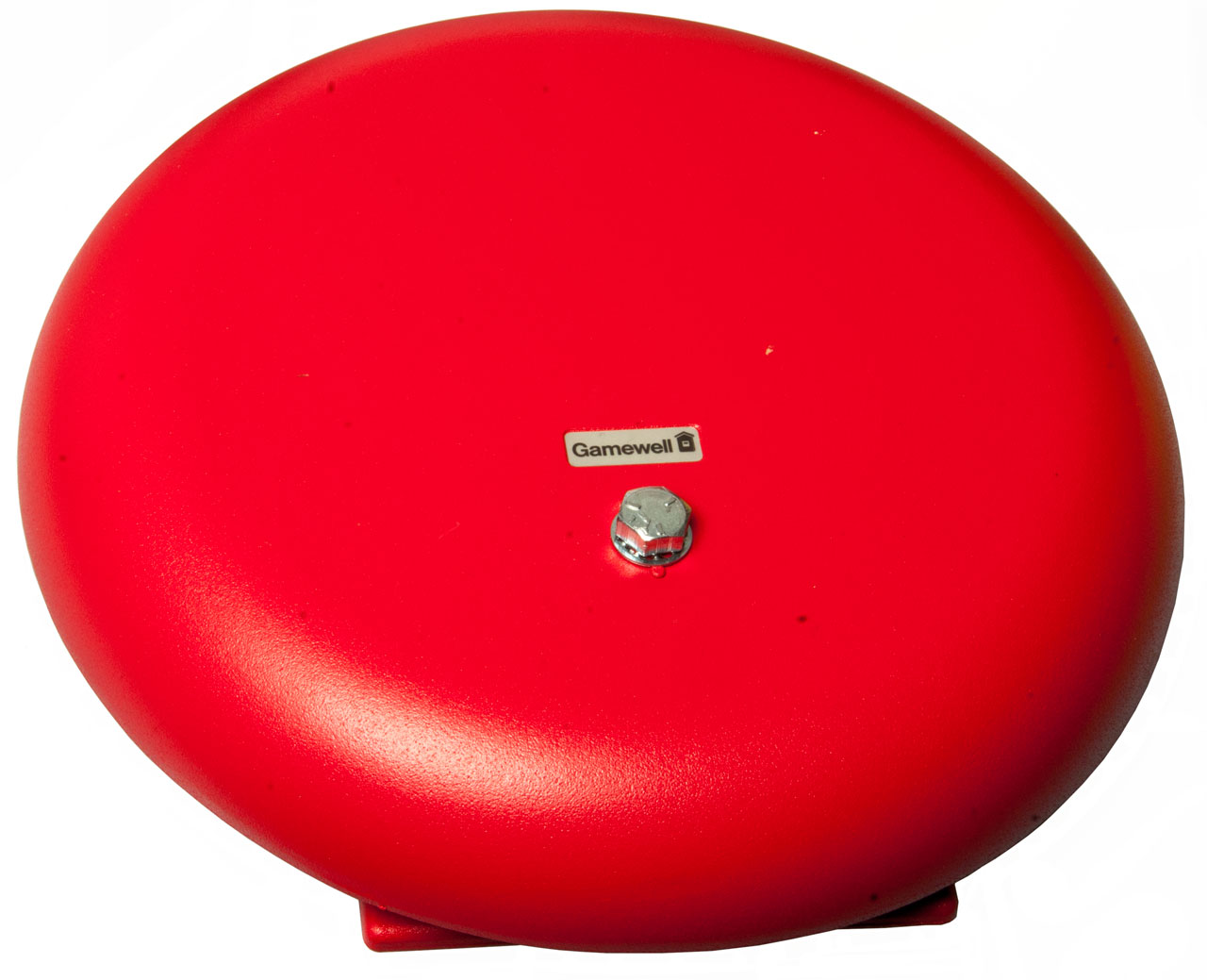
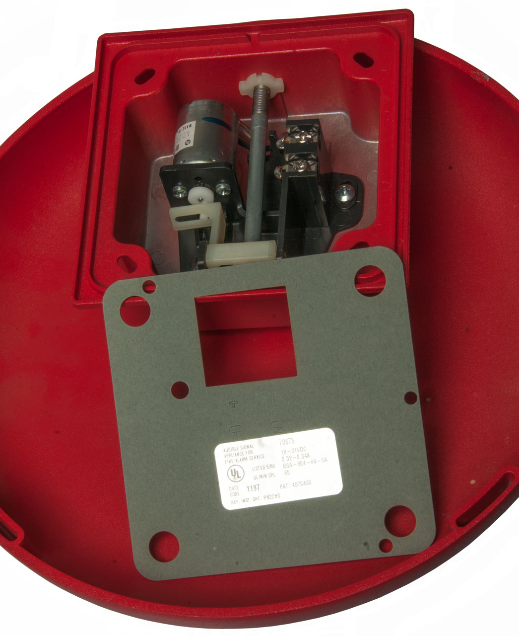
Gamewell 70875 Vibratory Alarm Bell
A small efficient DC motor moves the striker back and forth. Draws about 15 mA at 20 VDC. Notice that the Fish paper backing plate has polarity markings.
Gong is 10" diameter.
Label:
Audible Signal
Appliance for
Fire Alarm Service
UL Listed 578G
Date Code 1197
Ref. Inst. Sht. P82280
70875
18 - 31VDC
BSA-804-84-SA
UL Min SPL: 85
Pat 4970490
Fig 1
Fig 2
YouTube:
https://youtu.be/xQxehl7LBtA
Patent
4970490 Motor bell alarm, Stephen W. Andrews, Cooper Wheelock Inc, 1990-11-13, 340/392.2; 116/157; 116/159; 116/160 - motor drives cleaver mechanism that translates rotory motion into back and forth motion of striker
Calls:
4153898 Audible alarm with laminated magnetic core, General Signal Corp, 1979-05-08 - Reduces eddy current losses, see Self Winding Clock Co Laminated Core
4286259 Electrically operated bell, Kobishi Electric Co Ltd,1981-08-25 - motor drives a see-saw with striker at far end.
4360800 Gong striking mechanism, Kobishi Electric Co Ltd, 1982-11-23 - motor drives a see-saw with striker at far end.
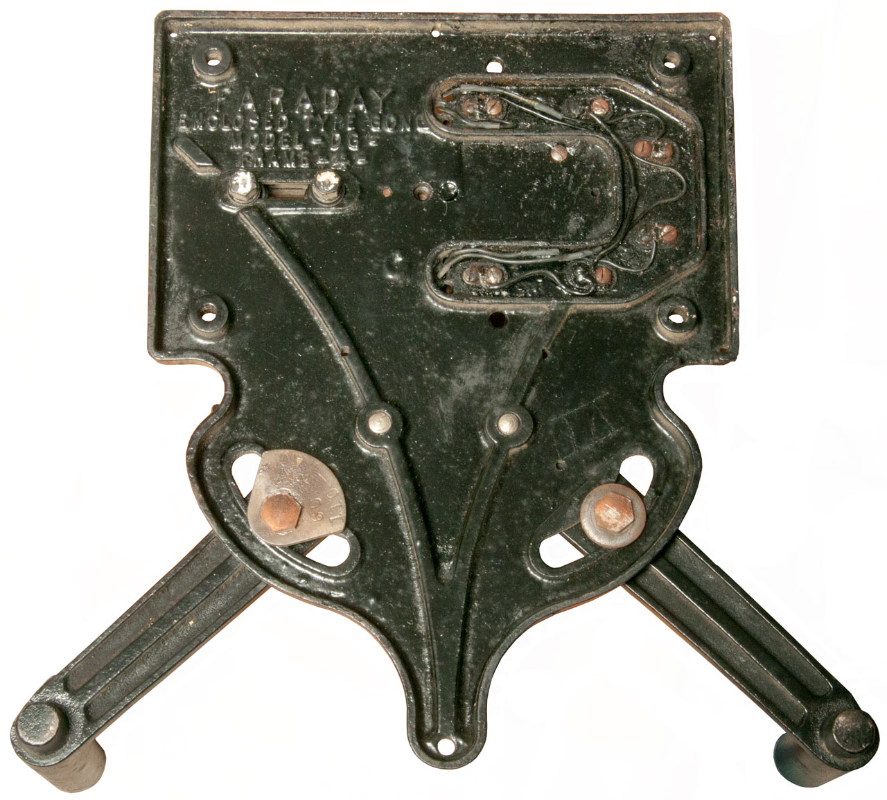
Faraday DG-4 Dual Gong
I had a mental picture of this as being maybe less than a foot across the two gongs, but it's MUCH bigger. Shipping weight 23 pounds. Each gong is 12" diameter.
The gong support arms are pivoted and so can accommodate larger and smaller gongs. They are now at the center of their range.
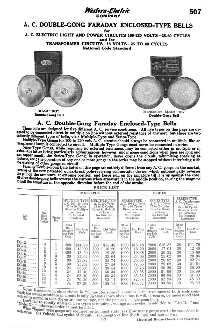
From the Western Electric Co. catalog (Fig 3 below)
"Faraday Double-Gong Bells listed on this page are entirely different from any AC gongs on the market, because of the new patented quick-break pole-reversing commutator device, which automatically reverses the pull on the armature at extreme position, and keeps pull on the armature till it is up against the core; all other double-gong bells reverse the current when armature is in the middle position, causing the magnets to pull the armature in the opposite direction before the end of the stroke."
So far have not found patent.
Photos
Fig 1 To fit into a smaller box the two gongs
were removed from the frame and stacked.
Fig 2 Faraday
Enclosed Type Gong
Model-DG -
Frame - 4 -
The tag on the left arm" 60-Cy, 110- VAC"
Fig 3
Page from Electrical Supply Year Book 1916
Faraday 8-1/4" x 6" Alarm Bell
eBay ad shows patent dates: July 2, 1907, Nov 26, 1907 & July 6, 1915 all associated with the Faraday bell, so I think the following patents assigned to Alice C. Patterson and the other patents assigned to her are all Faraday bell patents.
872145 Protective shield for skeleton-frame bells, George L. Patterson, Alice C. Patterson, 1907-11-26, 340/387.1 -
872146 Adjustment for Contacts, George L. Patterson, Alice C. Patterson, 1907-11-26, 340/392.1 -
901033 Electric bell, George L. Patterson, Alice C. Patterson, 1908-10-13, 340/387.1; 74/566; 340/392.1 -
910412 Electric bell, George L. Patterson, Alice C. Patterson,1909-01-19, 340/387.1; 174/549 -
1145507 Electrically-operated vibrator, George Lewis Patterson, Isaac Francis Badeau, Alice C. Patterson,1915-07-06, 340/397.4 -
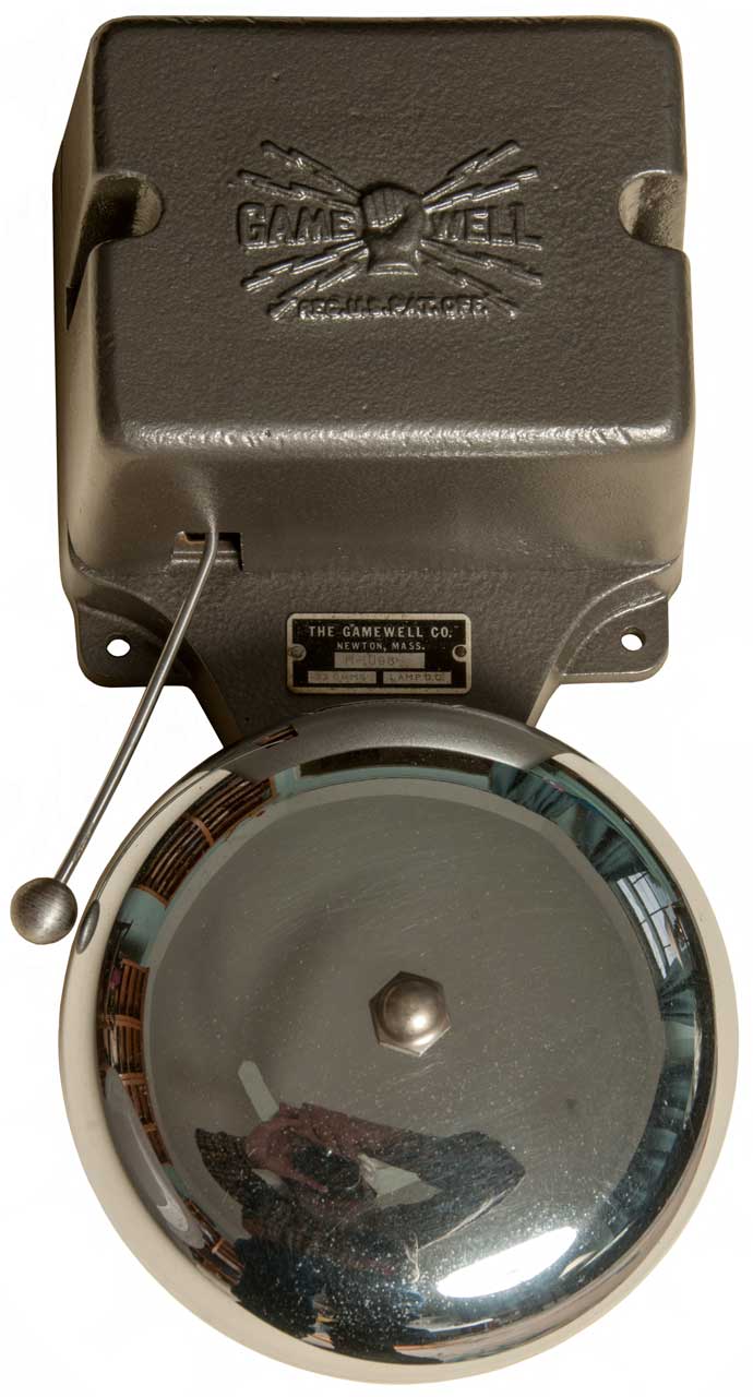
Gamewell M-1008 Tap Gong
This is not a vibratory bell or gong, that's to say it only rings one time for every pulse of current it receives.
When ringing a bell it is important not the have the striker stay away the bell since that would muffle the sound. Note there is an adjustment for the striker to bell gap. If you manually pull in the electromagnet the striker AWAY from the bell and when it is released the striker moves toward the bell, but when done manually does not ring the bell. In order to get the bell to ring the electromagnet needs to be activated and released smartly. More spring tension is associated with operation at lower voltages. A first try that works well enough to demonstrate the operation used a 45 V battery and 220 Ohm 2 Watt series resistor. The next try will be with a 90 Volt battery and higher value resistor so that the bell can be adjusted for a louder strike.
With 100 mA applied to the M-1008 the striker is pulled back all the way and the power supply reads 4.5 Volts. For a resistance of 45 Ohms for 4 each clip leads and the bell which is marked 33 Ohms.
That seems about correct. Note that the bell is operated with 100 mA current on a 24/7 basis. If the monitored loop is cut the bell will ring once and there's a remote chance someone will hear it. Also once you are used to the striker being way back from the bell, like when there's current flowing, just by sight you could recognize an open look since the striker will be very close to the gong. I think the long spring has stretched over time since adjusting it for more tension does not pull the striker from the electromagnet and does make the gong sound louder. But the threaded portion of the adjuster will stick out too far to allow the cover to be installed.
The frame and copper colored sub frame are both non magnetic.
Photos
Fig 1
Fig 2
Fig 3
YouTube 45 Volts & 220 Ohms
Bell adjusted to work
https://youtu.be/6tmZsHmgK7c
100mA Power Supply
This is a world wide AC supply (85 - 265 VAC input 50/60 Cycles) that puts out 100 mA with a max voltage of about 9 to 12 Volts.
eBay title: AC 85-265V 1x3W Power Constant Current LED Driver DC 9-12V 100MA
It uses the HA3201 8B05SS
The AC input goes through a full wave bridge and to a 4.7uF 400V cap.
The high voltage DC is stepped down and current regulated by the HA3201 8B05SS IC in conjunction with T1.
The SS110 is a 70 Volt 1 Amp Schottky rectifier diode.
I DID NOT use this because there is a direct connection from one of the AC terminals to the DC output.
The extreme shock hazard might be mitigated by using isolation transformers, but they are expensive.
Edwards 55 Bell
This is a vibratory bell, not a single strike gong. Designed to be mounted with the box above the gong, like the Gamewell M-1008.
They are both 6" bells, but the Gamewell appears larger because of the plating.
Fig 1
Door & Desk Bells
These are mechanical doorbells. Note the knocker should contact the bell only at the moment of striking. If it touches any other time it will dampen the sound. See San Francisco Cable Car Co. Bell above.
4816 Bell machinery for hotels (Annunciator), Tim D. Jackson, Alfred Judson, 1846-10-17, - bell rings and number drops
5969 Bell-telegraph, Jacob G. Day, 1848-12-19, - bell rings and number drops
21335 Call Bell, Albert W. Hale, 1858-08-31, - hotel front desk
39697 Improved call-bell, Nathaniel L. Bradly, 1863-08-25, - hotel front desk
39796 Improved door-bell, N.F. Cone, 1863-09-08 - Rotate exterior knob (3 lobes)
42107 Improved call-bell, Emery Parker, 1864-03-29, - hotel front desk, "Said wire is so bent as to allow the ball to strike the edge of the bell when the rod D is depressed, but not so as to rest against the edge of the bell to prevent the clear sound thereof."
89331 Improved door-bell, Orrin A. North, 1869-04-27, - pull knob
97617 Improved combined call-bell and table-caster, Henry A. Dierkes, 1869-12-07 -
128458 Improvement in door-Bells, Francis Blakemore, 1872-07-02 -
130690 Improvement in call-bells, Elijah C. Barton, 1872-08-20, -
128565 Improvement in door-Bells, William E. Sparks, 1872-07-02, -
D6493 Design for Ornamenting Bells, Otto F. Fogelsteand, 1873-03-18 -
150139 Improvement in door-bells, John P. Connell, 1874-04-28 -
Stewart Model 149A Army Chemical Warfare Service Siren
Also see Cars\Horns
1298428 Tuning device for signal-diaphragms, Frederik G Whittington, Stewart Warner Speedometer Corp, 1919-03-25, -
1344082 Portable signal device, John E Genn, Stewart Warner Speedometer Corp, 1920-06-22, - Army 149A. This is a Klaxon (Wiki) Awooga type device.
1566941 Electric motor for warning signals, Frederik G Whittington, Stewart Warner Speedometer Corp, 1925-12-22, -
Gamewell Fog Bell
Found on YouTube.
1478901 Signal-device-operating mechanism, George E King, Gamewell, 1923-12-25, -


Pen Registers
A pen register records on or off (digital) type information whereas a Chart Recorder (Wiki) records analog information.
1840
Samuel Morse invents the Telegraph symbols (see patent 1647 below) and uses a pen register to record them for later conversion to text. It turns out people working around the pen recorder quickly learn what character is being sent just by hearing it. The pen register is replaced with the telegraph sounder.
1846
In order to get a paper tape with letters and numbers printed for easy reading the New York Stock Market develops various "Printing Telegraphs" later called Stock Tickers. A young high school dropout arrives broke in New York to sleep in the janitor's closet where a friend works at the Gold Exchange and their system is broken. So T.A. Edison tells the boss that he can fix the problem, since everyone else does not have a clue what to do and gets the job. Starting in 1871 Edison patents a number of improvements to the Printing Telegraph and sells the patent rights and becomes famous.
1867
Syphon Recorder (Wiki) used to receive signals on first Transatlantic Telegraph Cable (Wiki). It's a very sensitive device made long before Vacuum Tubes (Wiki) were available.
1875
165379 Printing-Telegraph, John E. Smith, 1875-07-06, 178/35 - a Morse type printer with the look and feel of a Pen Register or Fire house alarm printer
Image from Wiki page: William Thomson, 1st Baron Kelvin who invented it.
1891
Strowger invents the dial telephone. It's not clear when, but the police find a new use for the pen register. When connected to a dial phone line it records all the outgoing numbers that were dialed. This was not public knowledge for many decades. The KS-3106 (single pen) and KS-3107 (dual pen) registers are intended for this application. Note "KS" indicates a Bell System specification, such as KS-8455 Telephone Lineman's "Kick Set".
Also see Spying on Cell Phones and FasTrak Vehicle ID Transponder.
1903
There is a problem in that ink is messy and the ink well need to be filled and cleaned. So a punch type register was patented, see 726882 below. Note punching paper tape results in Chads (Wiki) as a waste product. This means maintenance is required to dispose of them and keep the machine clean. The Register shown on page 29 of the Handbook of Fire Alarm Signalling, by The Gamewell Company shows a chad cup under the punch. Unfortunately there is no date on the book.
1909
After the paper tape is cut off and stored you can not tell in which direction it is moving. Note this was solved on the Teletype Automatic Send Receive (ASR) terminal (Wiki, photo) by shaping the paper tape tear off punch cover in a "V" shape. That way it's easy to see which end is which.
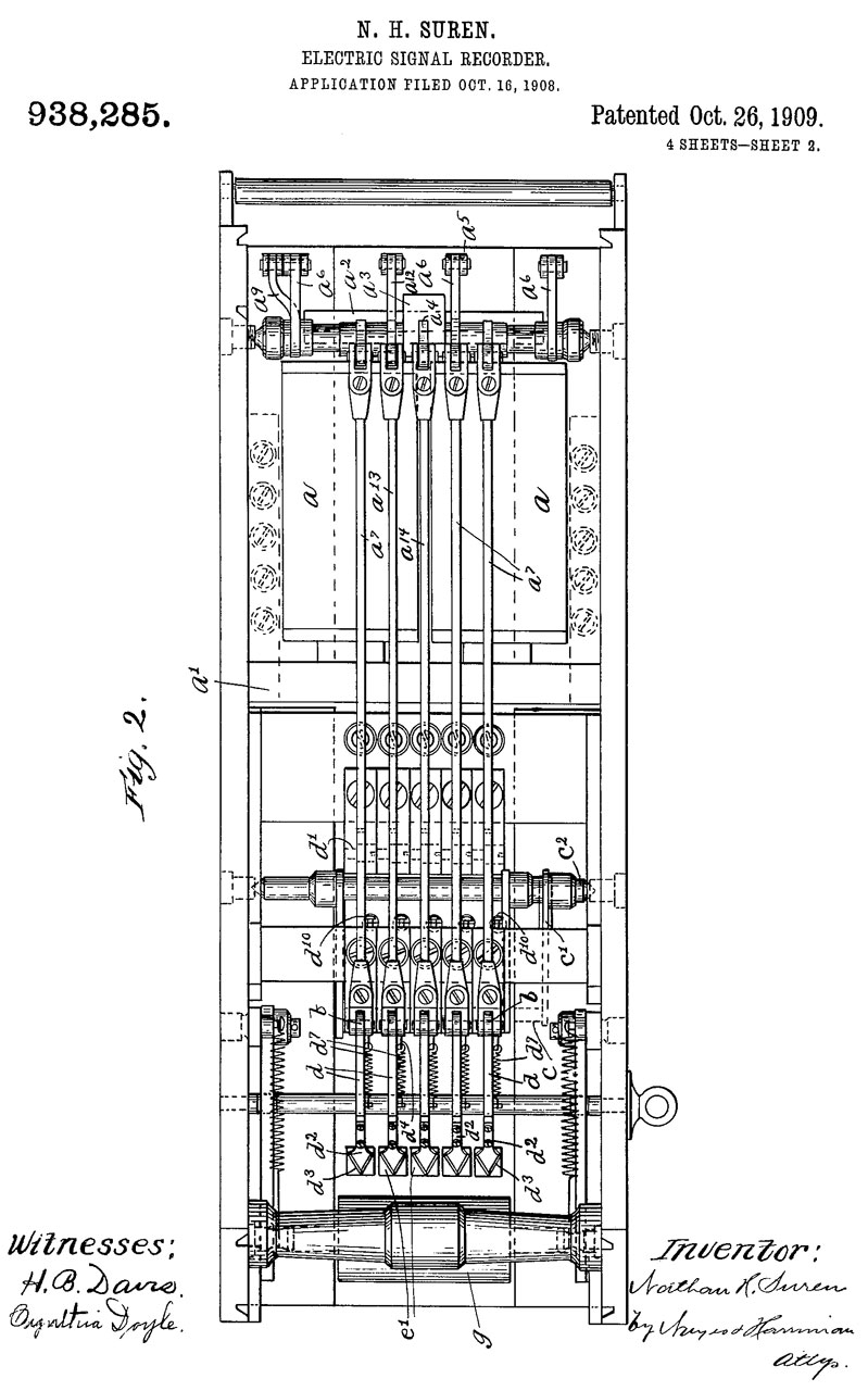
But the solution in this case was to make a triangle shaped hole, Gamewell patent 938285 calls it a "tongue" since there is no chad. This solves both the ink problem and the which-way-is-which problem.
Pen Register Patents
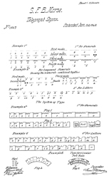
1647 Telegraph Signs, S.F.B. Morse, Jun 20, 1840, 178/2R; 178/17R; 178/86; 178/89; 341/66; 178/70A - Uses pen register.
180700 Printing Telegraph, J. H. Bunnell, Aug 8, 1876, 178/41 - Not a Pen Register, but rather a Stock Ticker
359687 Municipal Signal Apparatus, B.J. Noyes,Municipal Signal Co., Mar 22, 1887 - Police call box makes use of Break Wheel and ordinary pen register. But no claim is made for register.
487676 Electrical Signaling Apparatus, M. Martin, Dec 6, 1892 - 4 pen channels - can handle combined Fire & Police signals not printing some of the police signals.
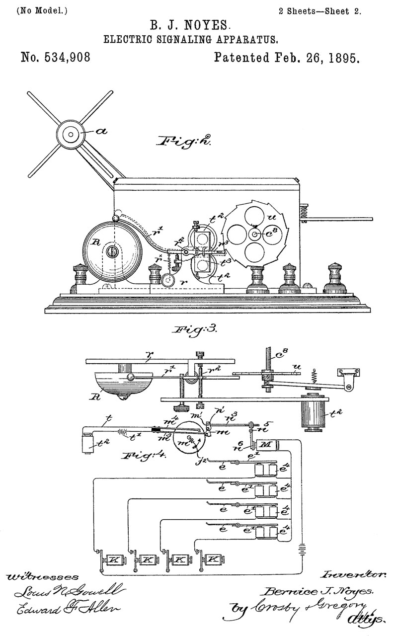
534908 Electric Signaling Apparatus, B.J. Noyes, Feb 26, 1895, 340/294 -claim is the addition of a bell, mot the register itself.
726882 Signal-recorder, Herman W Doughty, Clarence E Beach, Star Electric Co.,1903-05-05, 346/79; 101/474; 74/3.52; 192/139 - spring motor, released by electromagnet w/electromagnet for stamp or punch (not pen)
pg 4
938285 Electric-signal recorder, Nathan H Suren, Gamewell Fire Alarm Telegraph Co., Oct 26, 1909, 346/50; 83/70; 346/77R; 346/141; 178/92; 346/136 - cuts "tongues" which are folded back, not chads or ink. 5 channels.
From an eBay auction of 4 channel recorder.
938286 Electric-signal recorder, Nathan H Suren, Gamewell Fire-alarm Telegraph Co, 1909-10-26, -
938441 Message-recording apparatus, Francis A Skelton, 1909-10-26, -
1345355 Signal Recorder, H.W. Doughty, Gamewell Fire Alarm Telegraph Co., July 6, 1920 - "multiple pen registers" tape control.
1309720 Signal Recorder, H.W. Doughty, Gamewell Fire Alarm Telegraph Co.,July 15, 1919 - "multiple pen registers" tape control.
2392876 Recorder, C.E. Potter, J.W. Kendall, Jan 15, 1946 -
3350717 Plural Pen Recorder, G.M. Thompson, Oct 31, 1967
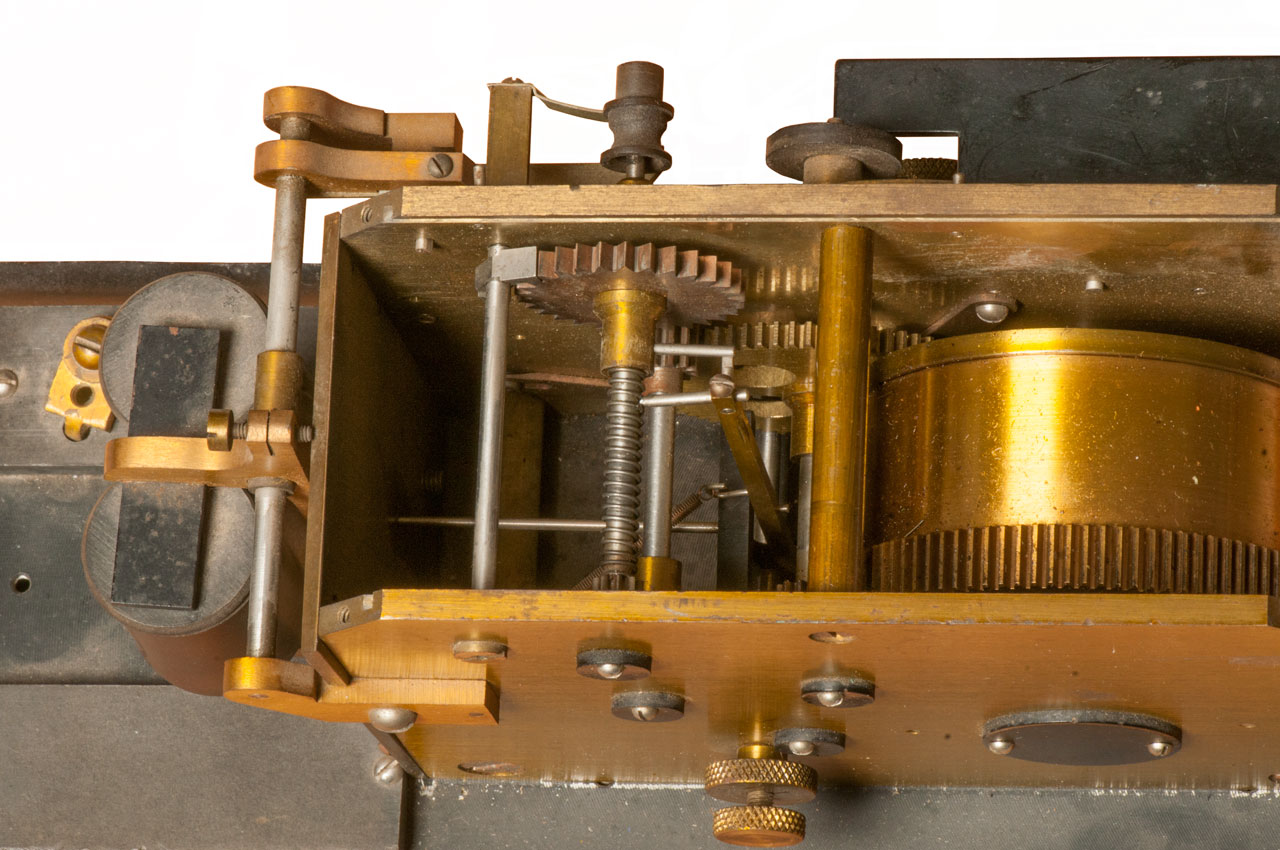
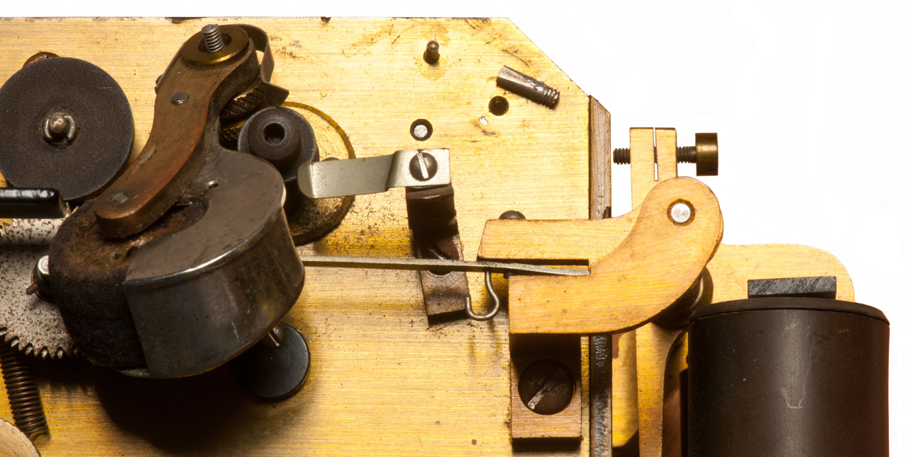
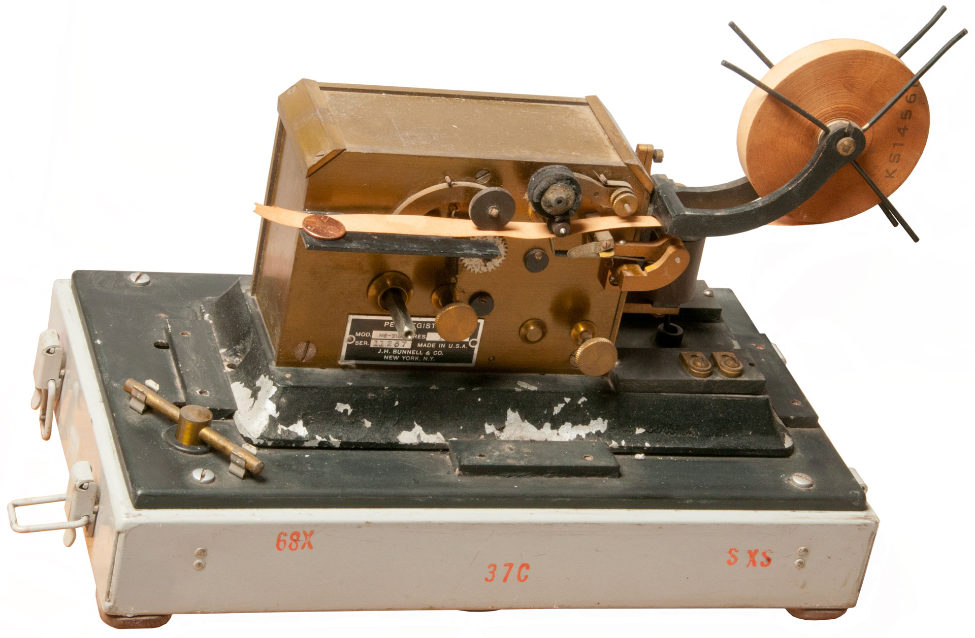
KS-3106 Pen Register
I think this was used to record outgoing phone numbers by recording the dial pulses. The coil is about 150 Ohms. It's smaller than I was expecting.
Bell System Practices Section: 030-341-701, Issue 4, Dec 1962 (pdf) -
1/2" Paper Tape
KS-1456D
Photos
s/n: 10676
Fig 1 The ink roller was inside & I have not figured out
how/where to attach it. The feed spool guide is missing
a screw and is all bent out of shape.
Fig 2 Even thought the return spring that lifts the pen is
missing the movement is stiff. So I applied a drop of Clock
Oil and the mechanism started moving. Then opened the
oil ports and oiled all of them.
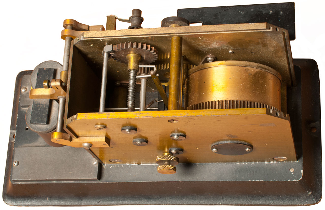
Fig 3 The next question is how to stop the movement.
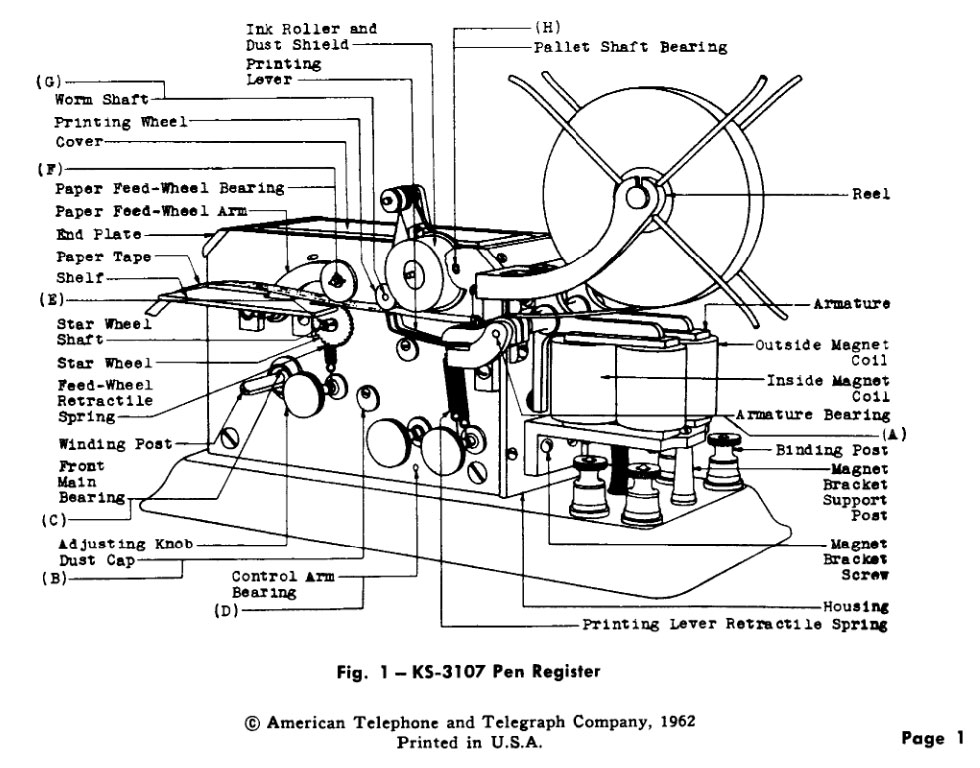
Page 1 of KS-3107 & KS-3107 Dual Pen version shown
YouTube: KS-3106 Pen Register
Shows worm shaft working. This is very similar if not identical to the Unison mechanism used in Stock Tickers.
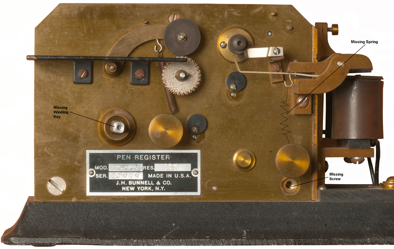
Fig 4 Front oil points & Missing Parts
Fig 5 view using new to me Sigma AF 50mm f/1.4 EX DG HSM lens for Nikon + lens corrections in Photoshop.
Fig 6 showing broken ink roller stud.
s/n: 11257
Fig 1 with bottom of carry case including winding key.


Horni Signal Strip Printer
This showed up on eBay with the title: "Vintage Very Early Horni Corp. Teletype Machine" and with a good photo of the patent number plate.
The Horni Signal company made traffic light and fire alarm systems. Patents by Paul Horni, Joseph Horni
Also see: Telegraph, Stock Ticker Patents,
1374606 Printing telegraphy, Pfannenstiehl Harry, WE, 1921-04-12,
1434290 Telegraph system and apparatus, Howard L Krum, Morkrum Company, 1922-10-31,
1448750 Telegraph printer, Edward E Kleinschmidt, Kleinschmidt Electric Co, 1923-03-20,
1564422 Printing telegraphy, Edward E Kleinschmidt, Morkrum Kleinschmidt Corp, 1925-12-08,
1565165 Telegraph printer, Edward E Kleinschmidt, Morkrum Kleinschmidt Corp, 1925-12-08, - 5-level typewriter like mechanism
1567392 Telegraph typewriter, Edward E Kleinschmidt, Morkrum Kleinschmidt Corp, 1925-12-29, - 5-level typewriter like mechanism
1567599 Telegraph typewriter, Edward E Kleinschmidt, Morkrum Kleinschmidt Corp, 1925-12-29, - strip printer in classic TTY case
1623809 Printing telegraphs, Pfannenstiehl Harry, WE, 1927-04-05, - 5-level typewriter like mechanism
1635130 Telegraph system, Howard L Krum, Morkrum Kleinschmidt Corp, 1927-07-05, - see also 1434290 - 6 level? synchronous
1745633 Telegraph receiver, Morton Sterling, Howard L Krum, Teletype Corp, 1930-02-04,
1783382 Electric selector mechanism, Howard L Krum, Teletype Corp, 1930-12-02, -
1811133 Printing telegraph, Edward E Kleinschmidt, Teletype Corp, 1931-06-23, -
1884743 Single magnet reperforator, Edward E Kleinschmidt, Teletype Corp, 1932-10-25, -
1917308 Pin barrel selector armature retaining type, Howard L Krum, Teletype Corp, 1933-07-11, -
1937376 Printing telegraph, Walter J Zenner, Teletype Corp, 1933-11-28, -
Time Register
2026 Jan: An eBay ad for "Antique Gamewell No. 15 Fire Alarm Time Register Recorder Brass Glass" has the look and feel of a Gamewell fire station alarm recorder, but it has five print wheels. Probably for date and time. The use case is not clear for the eBay item. It may be for recording working hours or the time & date of an alarm, or ...
I found another of these that has a wind up 12 hour clock on top with hour and minute hands. On the back of the clock there is what may be a once per minute electrical contact closure. This could be used to drive the printing mechanism. It might have been made by Chelsea Clock Co. (1920-1924)
This is similar to the Calculagraph.
177671 Electric Register and Time-detecter, H. Whittemore, 1876-05-23, - for use with watchmen
203689 Electric Register and Time Recorder, W.A. Wilson, (Chelsea, MA)1878-05-14, - papere feed wheels also puncture the paper as time markers
559518 Automatic time-recording instrument, H.F. Eaton, 1896-05-05, - has the look of an Edison Stock Ticker.
629366 Record-printing wheel for time-recorders, Foster J Hull, Walter Burchett, 1899-07-25, - prints large digits for hours, and smaller digits for minutes.
739224 Time-register, John L Roberts, 1903-09-15, - the printing wheels have the look and feel of those on the eBay Gamewell No. 15, but are driven by a clockwork.
Related
APX-6 IFF Transponder
Telegraph
Home Fire Protection - Hydrant - Hoses - Nozzles - Storage Tanks - Embers - Exterior Sprinklers - Mass Notification -
Indian Fire Pump
Kestrel 5500FW Fire Weather Pro
Stock Ticker Patents
Tuning Forks & Helmholtz Resonators - Links to Naval Postgraduate School of Physics
References
Web Archive: Gamewell - Our History -
Firefighters Hall & Museum - Minneapolis - The Fire Alarm Telegraph System -
YouTube
Bench testing a Gamewell street master box, 2:00, May 24, 2012 -
Gamewell Fire Alarm System - Jan 26, 2014, 3:03 - includes a number of call boxes, gong and paper tape register
AlmDoc41 - Intro -
Links
PRC68, Alphanumeric Index of Web pages, Contact, Products for Sale
Page Created 2019 February 25