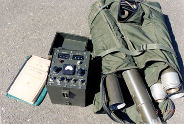

This is a one man back packable Light Weight Beacon. It includes a transmitter, 50 foot high antenna, and auxiliary parts. It was intended to be used as a navigational beacon for helicopters. A standard Non Directional Beacon (NDB) receiver found in most aircraft can be used for homing.
The manufacturer was Tridea Electronics, a subsidiary of McDonnel Aircraft Corp., 1020 Mission St., South Pasadena, CA mfg code # 13190.
- Transmit Frequency: 265 to 535 in 1 Kc steps (the DGPS Coast Guard stations are in the 283.5 - 325 kHz band- fully covered by this transmitter)
- Output Power: 10 Watts
- Prime Power: 12 Volt nominal battery (or external -26 VDC supply)
- Modulation Frequency: 1,000 cps +/- 0.01%
- ID code: 294 possible 3-letter Morse code groups
- Overall Block Diagram.jpg -
- Transmitter Wiring Diagram -
At the top end of the screw there is more than 1/2" of length where the threads have been machined off so that when the tuner is all the way up the screw can keep turning without binding.
At the bottom end of the screw there is about 3/4" of the rod
that has had the threads machined off for the same reason, to
keep it from binding at the lower limit.
Also there is a washer and a spring 0.9" free length,
0.445" OD made from 0.04" dia wire. The purpose of the
spring is to push the ferrite rod assembly back up into the
screw so that the screw can re-engage it from the lowest
position. Without the spring the assembly would fall due
to gravity and could not be lifted again.
To repair it will require getting a new screw made and a replacement for the fiberglass "nut".
Around the bottom of the loading coil there are a number of snaps. The ground plane/counterpoise system has a number of 8 mm film reels that have metalized mylar tape with a matching snap. There are two tapes for each snap. This provides a light weight way to carry a lot of conductive material. There is a winding mechanism to spool the tapes.
(you need Volo View to see *.dwf files)
W6 - 123480 - Battery Output
This is a 19" long cable that connects to the Transmitter Power Input connector J1.
The connector that mates with J1 is marked Deutsch DM 9702-3S (it has 3 sockets) 1265 - data code Dec. 1965
The other end has 3 small 0.1" dia x 0.275" long banana type pins in a triangle pattern. The triangle is NOT equilateral, it has sides of: 0.345", 0.345" and 0.25".
The three pins probably plug into a 12 Volt battery.
The J1 Pin assignment seems to be:1 = -26 Volts - There is a -26 V to +12 Volt Dc to Dc converter in the transmitter.
2 = 12 Volts
3 = Common = the pin that is furthest from the other two on the battery sideW1 - 123485 - External Generator
This is a 14 foot long cable that has the same Deutsch DM 9702-3S on the transmitter end.
On the other end there are 2 standard banana plugs with Red and Black sleeves marked +26 and -26.W7 - 123445 - Battery Charge from generator
Big alligator clips on one end: Red marked E1 (+ 26 V) and Black marked E2 (-26 V)W2 - 123420 - Transmitter Output (missing from my set)
The transmitter J2 Amp Control Connector is a Bendix MS 3114E-10-6S (6 sockets) military circular connector.
There are 2 lugs on the outside to engage the mating connector.
The pin assignments are:A = RF groundThe Connector at the base of the antenna tuner is a Bendix PT07A-8-4P (4 pins/plugs)
B = Earth Ground
C = low side of DC screw turning motor
D = hi side of DC screw turning motor
E = to J1#3
F = ground (the W2 cable has a jumper from E to F.
There are 2 lugs on the outside to engage the mating connector.
The pin assignments are:A = Wire to the lower end of the CoilFigure 1-2 in the manual shows W2. Estimated length of W2 is 2 feet.
B = Earth Ground (metal plate at bottom of antenna tuner) inside ant tuner called E1
C = Black tuning motor wire called E2 inside tuner
D = Red motor wire called E3 inside tuner
Eight Silver-Zinc sealed wet cells and solid state 0.3 amp. recharging circuit. Full charge voltage is 16.2 Volts.
Capacity is 4 Amp Hours before recharge is needed.
It is an equilateral triangle maybe 6" on a side. The angles of 60 deg. are used as a guide when locating the guy stakes.
There is a pin 1.100" in diameter that goes into a recess in the bottom of the antenna loading coil.
The pin should be about 0.2" high since the recess is 0.25 deep.
These are different from the Light Weight Beacon in that these use the motor to change the inductance of a coil by shorting or tapping the coil rather than using a movable core as in the above case.
Bandhopper - 3.7 to 30 MHz & 600 Watts
Super Antennas - KW3 - 75 through 10 meters & 2,000 Watts
Stealth Antennas - Stealth-2000 - 6m to 80m in 3 models & 1,000 or 3,000 Watts depending on model
GLA Systems - Texas Twister - 2000 - 80 through 10 meters & 200 Watts
High Sierra Antennas - HS-1500 - 3.5 through 30 MHz + 6 meters & 800 Watts PEP, 400 Watts average
DK3 - Don Johnson W6AAQ - 3.5 - 30 MHz, 1 kW?
Possible patents related to permeability tuned inductors.
2458282 High-power permeability core inductance, George J Maki, Collins Radio Co, 1946-11-16 -
2961657 Mobile antenna structure, Hodges Hato Rey, Fred J Schnell, 1956-07-09 - screwdriver?
Brooke's Products for Sale, Navigation, Home Brooke's Military Information page