Students learning Morse code have
had a variety of commercially made practice instruments
available to them over the years to assist in their studies.
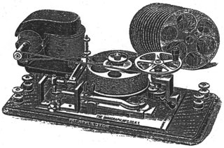
Such devices included purely mechanical sounders that simulated
the audio of a working sounder (fig. 1), inexpensively made
sounder/key combination sets identical in function to the more
robust instruments for commercial use, a variety of perforated
tape devices such as the Instructograph, Teleplex, AA
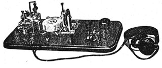
Transmitter, and others, a rotating painted cylinder device
called the ‘Natrometer’ (
fig. 2), as well as
a variety of 78 RPM and later 33 RPM records and tapes.
Fig. 1: “No. 1 Mechanical Telegraph
Instrument” is the name for this device in the 1912 J.H. Bunnell
catalogue. Bunnell made another variety of mechanical sounder,
and a number of other manufacturers also made such purely
mechanical instruments including Manhattan Electrical Supply
Company, and British companies.

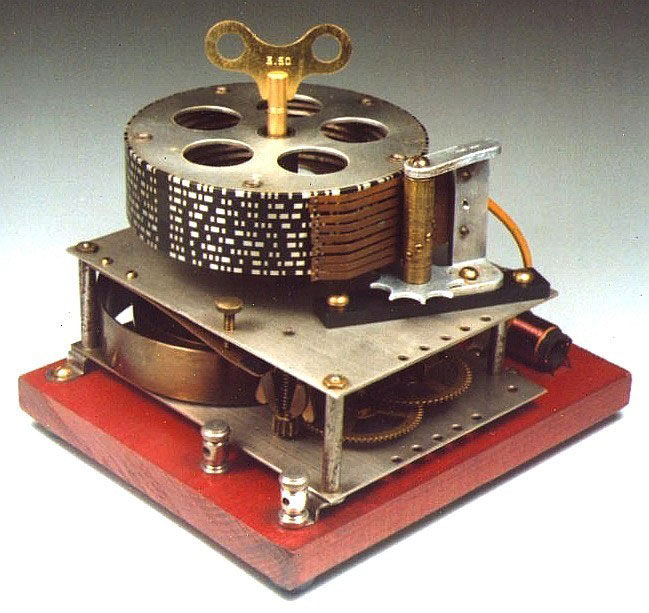
Fig. 2: Natrometer. A clock motor drives a
rotating aluminum drum painted in dielectric (insulating) paint.
The unpainted surface is in the shape of continental code
characters. A stylus in contact with the surface of the
drum automatically travels from one line of Morse code to the
next higher line and then back down the lines of code.

Current generation Morse code practice instruments employ
microprocessorcontrolled random character generators capable of
almost any sending speed. PC based software programs for
learning Morse code are also widely available. Among the
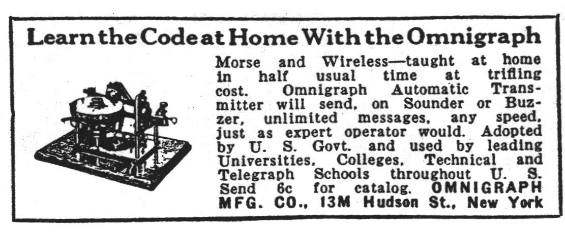
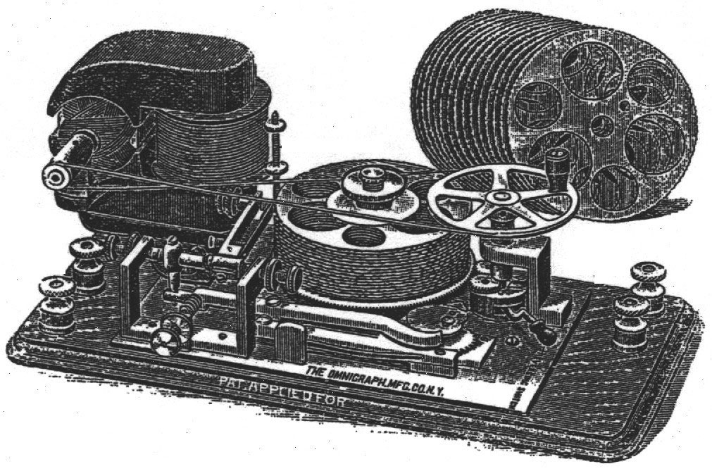
most unusual Morse code practice devices were those manufactured
by The Omnigraph Manufacturing Company in New York City between
1900 (
1) and 1931 (
2). As
best as can be determined, the Omnigraph company never produced
anything other than Morse code practice devices, and did not
produce commercial devices such as telegraph keys or sounders of
any sort. Omnigraph advertisements were featured in numerous
telegraph, radio and electrical publications of the day
including QST, The Wireless Age, Modern Electrics, The
Electrical Experimenter, Journal of the Telegraph, Radio,
Electrician and Mechanic and probably others (
3).
Omnigraphs were also marketed by major retailers of the day
including Sears and Roebuck, J. H. Bunnell, Manhattan Electric
Supply Company (‘MESCO’), and Wholesale Radio Service Company
(New York City). The factory occupied several different New York
City addresses over the 30+ year span of the company existence,
judging from the addresses listed in the numerous advertisements
during this time period. The 1914 and 1919 U.S. Department
of Commerce rulebooks stated that commercial and amateur radio
license examinees undergo a code test that: “shall consist of
messages with call letters and regular preambles, conventional
signals and abbreviations, and shall in no case consist of
simple, connected reading matter. The test will be conducted by
means of the Omnigraph or other automatic instrument wherever
possible (
4)”. The demise of the company
and its unique instruments was undoubtedly related in part to
the superior capabilities, versatility, and reliability of
perforated tape devices such as the Instructograph. As dazzling
as Omnigraphs were to watch in use, they were finicky and
temperamental instruments to use. The multi-disc Omnigraph
devices (see below) although ingenius in design, allowed for, at
best, pseudo-random code generation, limiting overall utility.
Although company advertisements boasted a 45 minute running time
on a single winding, a properly functioning and adjusted
instrument would begin to slow noticeably after about 20 minutes
running time (
5).
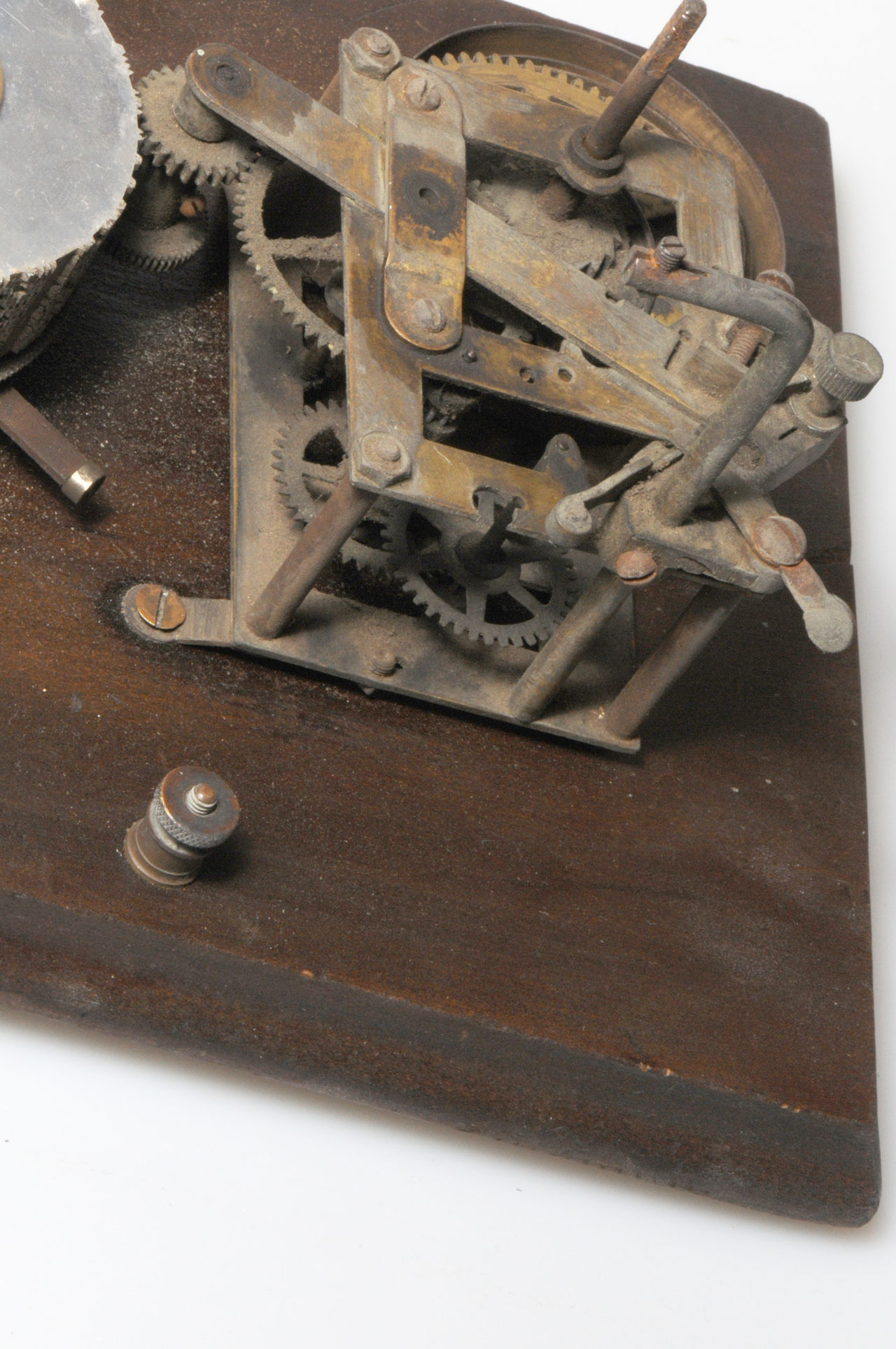
The Instruments
The company manufactured a number of instruments of varying
complexity, all of which had rotating aluminum discs with Morse
code characters incised into the edges of the discs as raised
teeth. As the disc rotated, a tracking stylus in contact with
the teeth was displaced by the raised teeth, and allowed an
electrical contact to make and break a circuit, producing the
Morse code characters. The instruments varied only in whether
the discs turned by use of a hand crank or were motor-driven,
and in the numbers of discs that could be stacked, necessitating
a cam mechanism which raised and lowered the tracking stylus in
the multi-disc models. Some instruments included keys, sounders,
or buzzers integral to the devices, although the company also
sold ‘stand-alone’ sounders, buzzers, batteries, and hookup wire
produced by other manufacturers as accompaniments to their
instruments. A student could purchase the Omnigraph instrument
alone, however for a few dollars more, the student could obtain
a package that
included a learner’s manual, a battery, a sounder or buzzer,
some wire, and a straight key. Although the company
advertisements described 5 models of Omnigraphs, (
Table 1), in reality, at least 15 distinct
instruments were advertised or produced over the years.
TABLE 1: Omnigraph Company Instrument
designations
| COMPANY DESIGNATION |
DESCRIPTION |
VARIATIONS |
| No. 1 Omnigraph |
Transmitter only or
transmitter/KOB combination
|
Two versions (figs. 7,9)
|
No. 2.Omnigraph
|
5 and 15 disc versions
|
5 disc model-four types
(figs. 12-15).
15 disc model-six types (figs. 19-24.)
|
No. 3 Omnigraph
|
Single disc transmitter
model with hand crank.
|
One version (fig. 8). Similar to Omnigraph
No. 1 (fig. 7)
but larger size wooden base.
|
No. 4 Omnigraph
|
5 disc model with key,
buzzer, and provision for headphones |
Two versions, (included
in No. 2 variations, above). (figs. 13,15)
|
No. 5 Omnigraph
|
Single disc model with
hand crank and clock motor
|
Two versions (figs. 10,11)
|
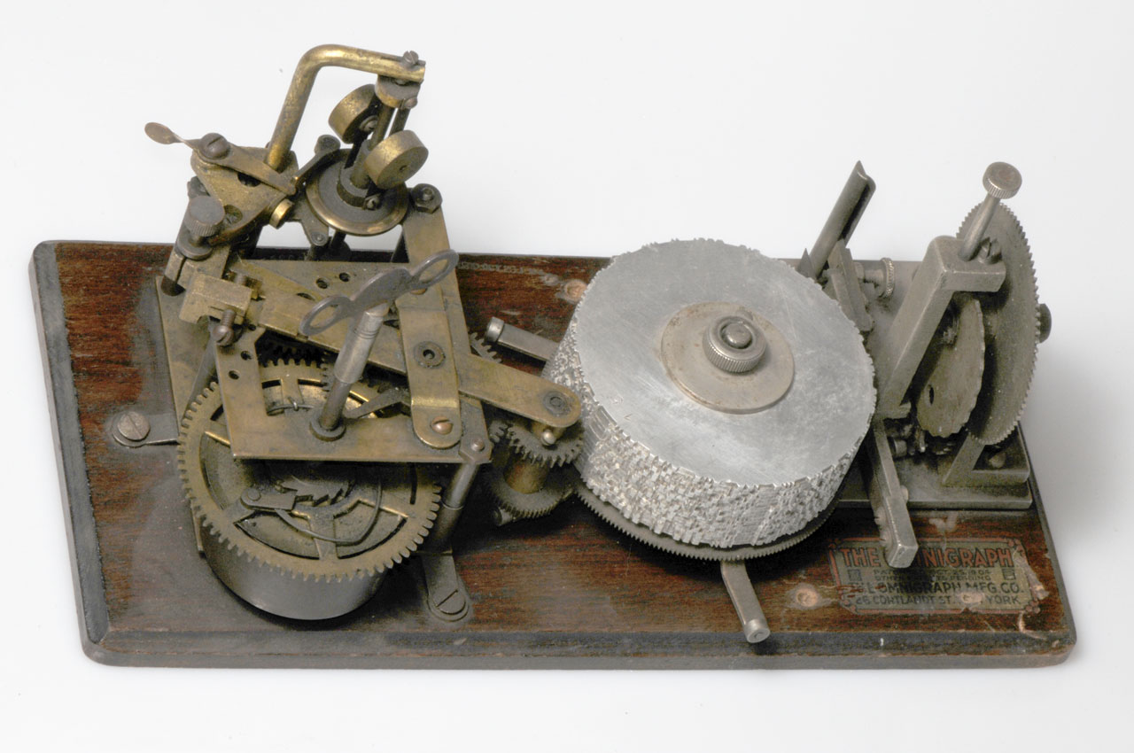
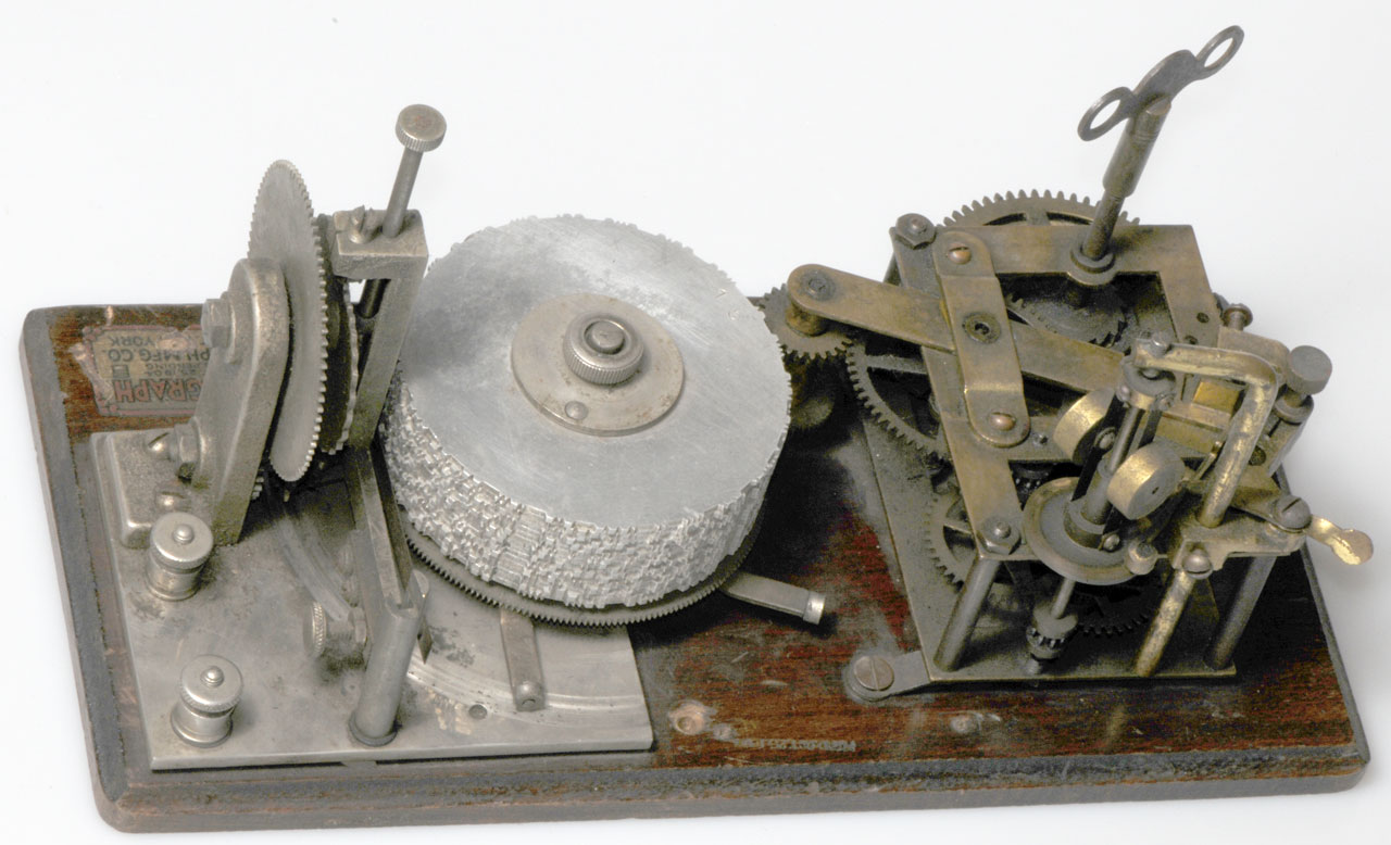
The instruments were mounted on wooden bases, which on most
models measured 5” X 10-1/2”. Many but not all instruments bore
a company identification label. Some were decals applied to the
wooden bases while others were metal tags attached by small pins
hammered into the wooden bases.
The company supplied Omnigraphs to others who affixed their
names to the instruments including the National Wireless
Institute (a study-at-home correspondence school) in New York
City, and A. W. Gamage, Ltd., London. Most Omnigraphs have
the notation ‘Patented’ or ‘Pat.’ embossed into the wooden
bases. A c. 1910 Omnigraph catalogue has a diagram of a No. 5
instrument bearing the patent date Oct. 25, 1903. The only
instrument with a patent date encountered by the author was a
5-disc instrument bearing the patent date of Oct. 23, 1904. To
the best of the author’s knowledge, there has been no research
on the patents held by the company nor on the individuals who
designed instruments. Discs The unique feature of the Omnigraph
instruments is the use of rotating aluminum discs with raised
teeth on the edge in the shape of the actual Morse code
characters. Discs were of at least 3 different types (figs.
3-
5) and a fourth type
that appeared in an advertisement (
fig. 21)
but which has never been seen by the author.
Fig. 3: A typical disc from a multidisc
instrument. Notice the 5 concentric holes in addition to the
central spindle hole. In use, besides the central spindle post,
a second post must be fitted into one of the 5 holes to align
all the discs in the stack in a uniform manner to allow for
coherent messages that were spread over more than a single
disc. This disc is marked 9-O, representing the 15th disc
of the 9-series of discs. (The letter ‘O’ is the 15th letter of
the alphabet). Transcription of the Continental code reads: “SEE
SILAS FLA HEY ABOUT 5 AND 35 SIG W LEE”
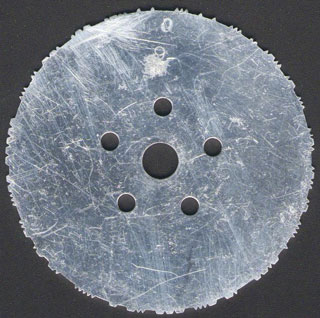
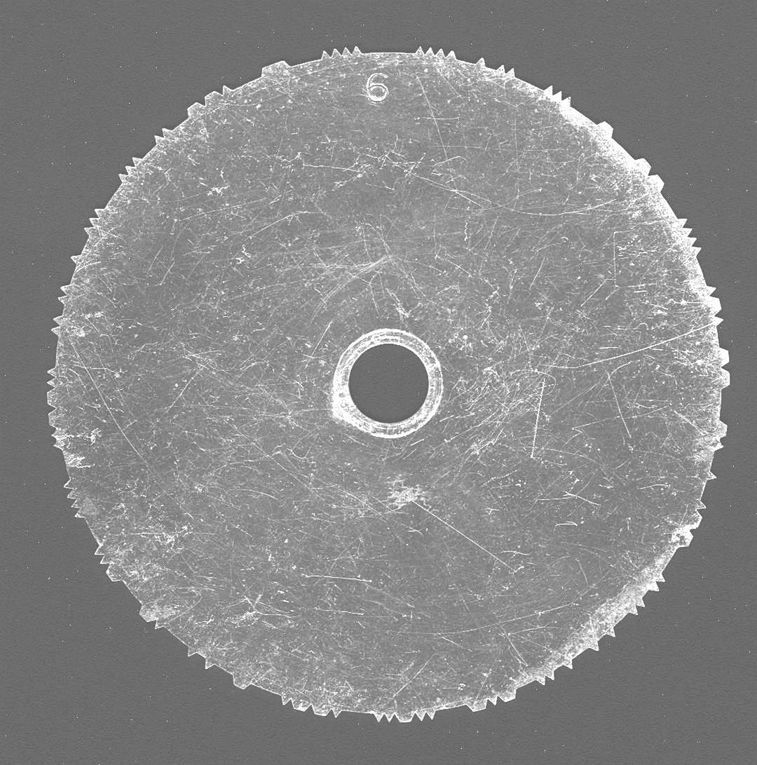
Fig. 4: A typical disc used on a single disc
Omnigraph instrument. A single central spindle hole holds the
disc onto the rotating platter. This particular disc is marked
“6”. Transcription of the American Morse reads: “HR STMH
FM NEW YORK 21 TO ADH. YES SIG LH”

Fig. 5: An unusual disc, with a central
spindle hole and two alignment holes. This disc is one of a
complete set of 15 found on the instrument shown in
fig. 23. This disc is the last disc (‘O’)
from the series, and bore no numerical designation. The
character consisting of 4 short dashes at approximately the 2:00
position on the disc is the Morse character denoting a new
paragraph (6). Translation of the Morse message reads:
“ON SALE CAN YOU SEE? ANSWER SIG L RICHARDS”

The discs were all 3-1/8” in diameter and were either thin
(1/32”) or thick (1/16”). Thin discs were used on the single
disc instruments, and had a single central hole for the spindle,
whereas thicker discs were used on the multidisc instruments,
and had alignment holes in addition to the central spindle hole.
Close inspection of the discs indicates that production involved
cutting the discs, analogous to a locksmith duplicating a key.
Such an arrangement would produce a disc with closer dimensional
tolerances than stamping discs from a die.
Discs were available for both American Morse and Continental
code. The number of characters on any individual disc varied
from 12 to 36 (
4) with the lower number of
characters allowing for slower code speed in the beginning
lessons and the closer spaced characters for more advanced
lessons. The speed of rotation of the discs, of course was user
modifiable, allowing further control of sending speed. Code was
sent using the ‘Farnsworth Method’ indicating that the
individual Morse code characters were uniform in dot and dash
length and spacing with slower code speeds achieved simply
allowing more time between individual characters. The thicker
discs could be used on the single disc instruments but the
thinner discs were physically incompatible with the multi-disc
mechanism, which required a second alignment hole. Practice
sessions included code groups, random characters, numbers,
punctuation, and short messages (
fig. 6).
Fig. 6: Transcription of the full disc series
of Continental code for the 7-series of discs.
(Transcription courtesy of Mr. Lynn Burlingame N7CFO).
7-A
|
III
SS AS HOOKER OFF LB NJ SEPT 15 TOT
|
7-B
|
BROWNS
OPR
STR BRITTON VIOLENT RAIN AND
|
7-C
|
WIND
STM RAGED AT ASBURY SE OF US THIS MNG
|
7-D
|
DAMAGED
THE
TOWN AVON. 2 LIVES IN PERIL
|
7-E
|
BY
FIRE ON SHIP KENNEDY BEACHED HERE. B
|
7-F
|
GEO
DENTY
KEY ESCEBETTS FRANK R. MILLERS
|
7-G
|
JOE
TEER JOHN Z. WORTON SAMUEL T. CORBIN
|
7-H
|
NAMES
FM POCKET OF ROB BENTLY SAVED,
|
7-I
|
TURKISH
HUSSARS
ARRESTED WHILE AT SCUTARI
|
7-J
|
MAN.
Q HIGGINS ON STEAMSHIP XE MEYER.
|
7-K
|
RECD
FM HATTARAS WED. 5 AM SEVENTEEN HUNDRED
|
7-L
|
WT
IS ZN HOPING FOR ? S FORD IS A VYGD
|
7M
|
.
IT WAS STATED IN ADVICE S. MURAD WAS PUT
|
7-N
|
TO
DEATH D’S NO IS 496 ADSMEAT 370N
|
7-O
|
SEA-AIR AVE 7 AM (SIG C HAROLD EBLIN.
|
Discs that were used on multidisc instruments (5 or 15 disc
models) were designated with an alphanumeric numbering system
consisting of a number followed by a letter between A and O
accounting for the 15 discs in the series. Other discs (
fig. 4) were designated simply by a number. A
set of 15 discs exists that is labeled A through O with no
number designation (
fig. 23).
It is not known with certainty but it is suspected that the
discs for single-disc instruments were numbered whereas the
discs for instruments employing multiple stacked discs bore the
alphanumeric designations. Alphanumeric discs are known up the
‘9’ series however it is unknown if more than 9 sets of discs
exist. The lowest numbered series of discs (series 1 and 2 for
example) had simple code groups whereas the highest numbered
series (
8 and
9) had more
complex messages including numbers and punctuation characters.
Nine sets of 15 discs may exist for both Morse and continental
code for a total of 135 discs for each code. The highest
numbered disc encountered by the author is ‘19’, suggesting that
at least 19 numbered discs exist.
Discs from the “2” series exist for both Morse and Continental
code, and transcription indicates that the messages were
completely different indicating that the Morse and Continental
code discs were not simply the same messages in Morse and
Continental code.
Morse discs were identical in appearance to Continental code
discs and the company made no attempt to differentiate one from
the other based on appearance. The only way to tell Morse from
Continental discs is to visually inspect the discs, looking for
the characteristic Morse characters that were distinct form the
continental code characters.
In addition to the discs that were included with the initial
purchase of the instrument, additional discs could be obtained
at modest cost. The company also permitted students to exchange
their discs for different ones for a 2 cent per disc postage and
handling fee. If one ordered 5 extra discs for a 5 disc
instrument, it is suspected that the student would receive the
first, second, or third set of 5 discs of a 15 disc sequence.
Transcription of the discs has demonstrated that sometimes the
company mislabeled the discs. A 7-L disc owned by a collector is
the same as a 7-I disc in the author’s collection. Other
collectors have other discs with the same messages on discs with
different alphanumeric designations suggesting incorrect
labeling. The author has several alphanumeric discs with the
letter crossed out and another letter stamped next to it as a
correction. Another disc has the letter designation on the disc
upside down. The finding of inconsistent and erroneous labeling
of discs suggests that disc labeling was not automated, and that
human errors were not rare in labeling discs.
The author’s experience and the anecdotal experience of other
collectors is that most discs encountered are the thicker discs
used in the multidisc instruments. The 6 thin discs in the
author’s possession are all American Morse.
The Clock Motors
Another feature of some of the Omnigraphs is their use of a
spring-driven windup clock motor. An interesting adaptation is
the use of a flying-ball governor mechanism to maintain constant
speed in the face of a marked increase in the instantaneous
loading, as when the stylus tracking mechanism moved from one
disc to a higher disc in a stack. In reality, the sending speed
slowed as the tracking stylus moved to a higher disc, and
frequently would flub the first character on the higher disc. As
the stylus descended the stack of discs, frequently it would
skip the adjacent disc and track to a lower disc, although this
may have been secondary to wear on the cam mechanism. The clock
motors on different instruments varied slightly in design over
the years but all had the flying ball governor, and a friction
speed control mechanism. An experienced clock repairman
indicated to the author that the clock motor resembles a Seth
Thomas clock mechanism of the era with the addition of the
governor, and that most likely Seth Thomas provided the clock
drives to the Omnigraph company. The motor mainspring is
presently an off-the-shelf item from clock repair parts sources
and can easily be obtained and replaced on existing instruments
if needed.
The Simplest Omnigraph
The simplest Omnigraph device consisted of a single disc mounted
on a platter which was rotated by use of a hand crank (
fig. 7).
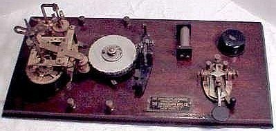
Fig. 7: “Omnigraph Transmitter No. 1”, the
simplest device the company produced. The user had to supply his
own battery, buzzer or sounder, wire, and key.

Advertisements in 1909 listed this model as “The Omnigraph
Transmitter No. 1”. The single disc supplied with the instrument
had American Morse characters which sent the nonsense statement:
JOHN QUICKLY EXTEMPORIZED FIVE TOW BAGS, which incorporates all
26 letters of the alphabet into one sentence. No numerals or
punctuation were included. An instruction booklet “How To
Become An Excellent Operator” was included with purchase of the
device. Additional discs could be purchased for 5 cents each.
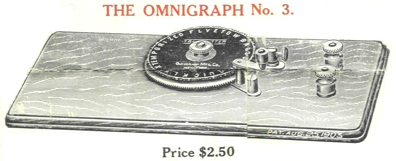
The same device on a larger base was known as “The Omnigraph #3”
in a c. 1910 catalog (
fig. 8).
Fig. 8: “Omingraph Transmitter No. 3” is the
same instrument on a larger wooden base. From a c.1910
Omnigraph Company catalogue.

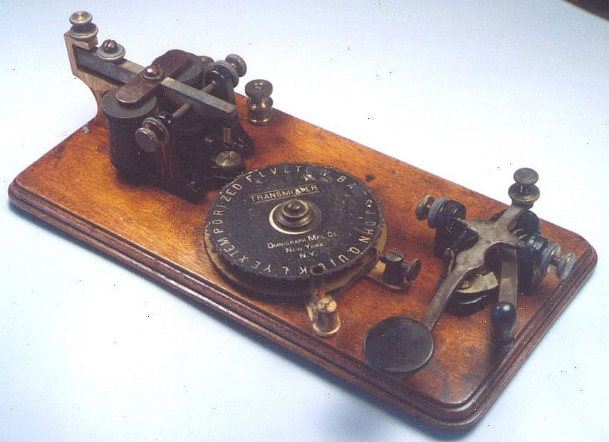
Omnigraph KOB
A device similar to the simplest Omnigraph (above) incorporated
an inexpensive sounder and key identical to the J.H. Bunnell
“Morse Learners’ Outfit” advertised in the 1900 Bunnell
Catalogue, and were undoubtedly supplied to Omnigraph by
Bunnell. (
fig. 9).
Fig. 9: Omnigraph transmitter with integral
key and sounder. This instrument is missing the hand crank used
to turn the platter containing the disc.

There was no separate model number for this device, and it was
regarded as a version of “The Omnigraph Transmitter No. 1.” The
1903 MESCO catalogue listed this device as “Omnigraph Learner’s
Set”. A ‘press release’ in the April 16, 1901 issue of The
Telegraph Age described this device suggesting that it may be
the first instrument produced by the company.
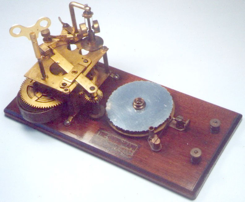
Single Disc Omnigraph with hand crank and motor
Due to the inconvenience of having one individual hand crank an
instrument while another listens to the code, (or even worse,
trying to crank it yourself
while attempting to copy Morse code), the company supplied a
device that allowed both for hand cranking and motorized disc
rotation (
fig. 10).
Fig. 10: “Omnigraph No. 5” is the company
designation for this model. At $7 around 1915, it came with a
total of 3 discs and a learner’s manual. This instrument is also
missing the hand crank as is
fig. 9.

The logic behind supplying such an instrument is unclear,
inasmuch as the hand-cranked mechanism would seem completely
superfluous in the face of the convenience of motorized use.
Despite the ease of having automated disc turning, the user was
still limited to a single disc at a time, and by having to
change the disc after every use. It must have been very tedious
for the student to listen to the same disc over and over, and to
have to change every disc by hand. It is speculative, but
undoubtedly at least some students thought to turn the disc
over, thus playing the disc backwards, generating new
characters. The letter A (.-) for example would then become N
(-.). A c. 1930 company catalogue illustrated a slightly
different version of this instrument on a smaller base and with
a more compact design (
fig. 11).
Fig 11: “Omnigraph No. 5” on a smaller base
with more compact design than
fig. 10.

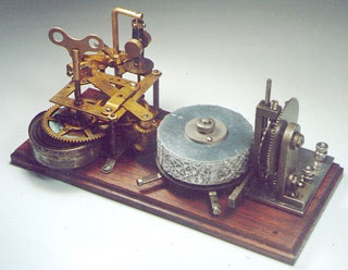
Five Disc Model
The 5 disc model was designated “Omnigraph No. 2 Junior” in the
1924 J.H. Bunnell catalogue. The five disc model (fig. 12) was
probably the most popular model (4), and incorporated the clock
motor, a stack of 5 discs, and a cam mechanism to move the
stylus from one disc to the next higher disc.
Fig. 12: “Omnigraph No. 2 Junior” is the
company designation for this model, and is reported to be the
most popular model sold (
4). A buzzer was
included in the purchase price of $12.50, or for $14 the device
came with a key and sounder, battery, wire, and a learner’s
manual.

When the stylus arrived at the highest disc, it would travel
down the stack again from the highest disc to the lowest disc
and then ascend again. An adjustable mechanism allowed the user
to decide whether to play the entire disc before moving to the
next disc in the stack, or to play a segment of the disc before
moving to the adjacent disc. 1/5, 2/5, 3/5,4/5 or the entire
disc could be played before moving on to the next disc. By
allowing less than a full disc to play before moving to the next
disc, the user could create nonrepeating messages much longer
than the sum of all of the characters on the 5 discs. For
example, if the user wished to play only 2/5 of the disc before
moving on to the adjacent disc, then when the disc reached the
highest level, it would begin to descend down the stack of discs
again, and would play a different 2/5 segment of each disc on
the way down. At the lowest disc, the stylus would begin to
ascend the stack of discs again, this time playing a 1/5 segment
of the disc that had already been played with the last 1/5
segment of the disc that not been played. This ingenius
pseudo-random character generator design would allow continued
playing of different 2/5 disc segments for many, many hundreds
of characters before repeating the message. By adjusting the
device to change discs after 1/5 of a disc, then 2/5, 3/5, 4/5
or a complete disc, students could produce a nearly infinite
number of non-repeating characters before repeating. Of course
shuffling the disc order, flipping the discs over, or rotating
one or more of the discs ‘out of phase’ with each other would
allow even more variety. Nevertheless, students may have
relatively quickly memorized segments of discs, diminishing the
utility of the device as a learning tool. The company also
manufactured a 5-disc device with a key and buzzer (
fig. 13).
Fig. 13: Omnigraph No. 2 Junior with
integral buzzer, key, and provision for use with earphones.
|
The governor is missing from the spring motor as is the
cover for the buzzer.
|
Advertisements for the 15 disc version of this device show
earphones being used. The small cylindrical object next to the
buzzer is a primitive coupling transformer for use with the
earphones described in a c.1930 company catalogue as “induction
coil #21”. The primary winding is in series with the buzzer, and
the secondary is connected to the earphone terminals. The audio
heard in the earphones would be the same frequency as the buzzer
and would be expected to mimic the raspy audio quality of spark
transmitter signals of the era. A similar coupling device is
present on the Natrometer (
fig. 2), and is
also present on a similar device advertised in a c.1919 Gamage
catalogue. The buzzers included on the Omnigraph devices so
equipped were almost certainly manufactured by Signal Electric
Company of Menominee, Michigan. Another version of the 5
disc model had the discs stacked on top of the motor (
fig. 14) in a compact arrangement.
Fig. 14: Compact 5-disc device.
Advertisement from an issue of QST c.1920’s

As best as can be determined, there was no separate model
designation for this device. A version of this model included a
buzzer and key (
fig. 15) similar to
fig. 13, and was manufactured for use by the
New York Wireless Institute, and which bore their name (
fig. 16).
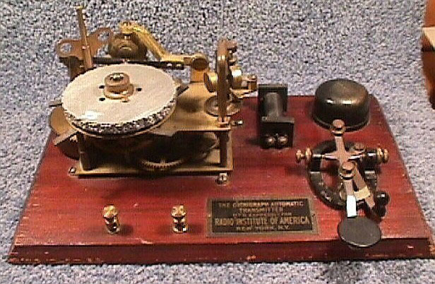
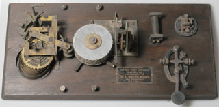
Fig. 15: Compact 5-disc Omnigraph with
integral key and buzzer made for the New York Wireless
Institute. (Photo courtesy of Mr. Lynn Burlingame N7CFO).

Fig. 16: Label on device shown in
fig. 13.
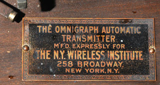
Although the New York Wireless Institute was a study-at-home
correspondence school, advertisements mention an on-site ‘post
graduate’ course. It is unknown how many students actually
studied at the ‘campus’. Of note, the address of the New
York Wireless Institute was 258 Broadway.
Between about 1910-20 the Vibroplex Corp. factory was located
directly across the street at 253 Broadway. Students enrolled in
the Wireless Institute ‘post graduate’ course of study wishing
to purchase bugs could conveniently do so at the Vibroplex
factory. Of interest, a c.1930 Omnigraph catalogue listed
Vibroplex bugs for sale including the #4 model (“Blue Racer”)
for wire work and the #6 model (“Lightning Bug”) for wireless
work.
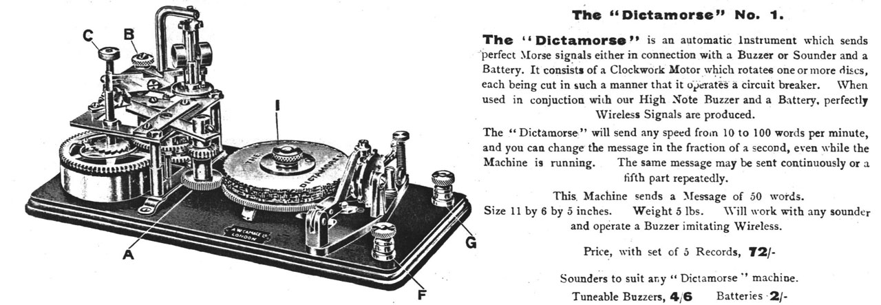
A typical 5-disc model Omnigraph was listed in a c. 1919 A. W.
Gamages (London) catalogue (
fig. 17) under
the name “The Dictamorse No. 1” and bore a Gamages label (
fig. 18).
Fig. 17: Typical No. 2 Omnigraph listed in a
c.1919 Gamage catalogue.

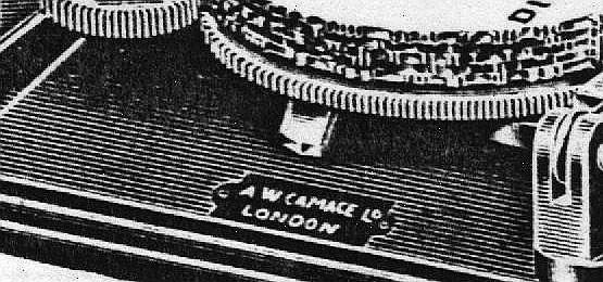
Fig. 18: Detail from fig. 17 showing the
Gamage label on the device. The label reads, “A.W. Gamage
London”

15 Disc Model
The fifteen disc model was listed in company advertisements as
“The No. 2 Omnigraph” incorporating the same driver motor as the
other models, but with a more elaborate cam mechanism for
changing the discs (
fig. 19).
Fig 19: “Omnigraph No. 2” is the name the
company gave to the fifteen disc model. This instrument is
probably on a replaced wooden base.
A version of this model advertised in 1909 as “The Omnigraph No.
2 Improved” used a battery powered motor and rheostat in lieu of
the wind-up motor (
fig. 20).
Fig. 20: “Omnigraph No. 2 Improved” is the
company designation for the electric motor driven version of the
No. 2. Omnigraph.
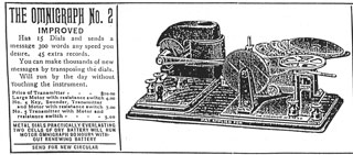
An elongated drive belt connected the drive shaft of the
electric motor to the rotating platter. A total of 60 discs was
included with this model. At $10 in 1909, this amounted to
nearly a weeks’ wages for a typical worker, making the purchase
of this instrument a very serious decision. A slightly different
version of this instrument with a different design cam mechanism
also allowed for hand cranking (
fig. 21).
Fig. 21: Another version of the “Omnigraph
No. 2 Improved” with a different type of cam mechanism and a
provision for hand cranking the instrument. Notice the different
style discs with large holes. The author has never seen these
discs such as these and wonders if they were ever produced.
A slightly different version of the 15 disc model advertised as
“New Omnigraph No. 2” in 1910 employed the wind-up motor and
also had the capability of hand cranking the device if desired (
fig. 22).
Fig. 22: “New Omnigraph No. 2” from a 1910
advertisement. The 15-disc instrument could be powered by either
the clock motor or a manual hand crank. Notice the user wearing
earphones. Auxilliary equipment such as a buzzer or oscillator
must have been present and not illustrated.

As with the single disc device that has both motorized or manual
drive (figs.
10,
11),
the author wonders why the hand crank mechanism is included with
motorized capability. It is possible that the company knew that
the clock motors wound down very rapidly and that students
working in pairs probably represented a more efficient way to
use the instrument. In addition, a human could probably crank
the machine more forcefully, minimizing the slowing that
occurred when the cam mechanism moved the stylus from one disc
to the next higher disc.
A version of the 15 disc model exists that has the hand-crank
mechanism, and no motor drive, with extra stacked discs where
the motor would be
normally located (
fig. 23).
Fig. 23: Hand crank instrument with no clock
drive. This unique instrument was never advertised to the best
of the author’s knowledge, and contained 30 Morse discs with 15
in use and 15 spares. This instrument contained the unique discs
shown in (
fig. 5). (Photo courtesy of Mr.
Mike Feher N4FS).

The company also supplied a 15 disc device with a buzzer and
straight key, to the New York Wireless Institute (
fig. 24).
Fig. 24: Omnigraph #2 with integral key,
buzzer and provision for earphones. from a 1920 advertisement in
QST for the New York Wireless Institute. Similar to
fig. 13, except with 15 discs. Students
enrolling at the institute received this instrument according to
the widespread advertisements for the school.
Conclusion
The Omnigraph company advertised or produced at least 15 models
of telegraph learning devices over an approximately 30 year span
early in the 20
th century (Table 1). There may be
other devices or variations thereof not listed here that may
come to light, and the author would appreciate hearing about the
existence of any such devices from readers. It should be noted
that a number of the devices described (above) are known only by
their advertisements. Telegraph manufacturers in the early 20th
century are known to have advertised items that are completely
unknown today, and it is uncertain if they were ever produced (
8).
Devices similar to the Omnigraphs that appeared after the demise
of company had an incised wheel which would send “SOS”
repeatedly and were presumably of WW-II military origin.
Interestingly, in 1963, long after the demise of the company, a
device was advertised in CQ magazine identical in function to
the Omnigraphs (
9). It consisted of a
motorized circular wheel with the Morse code characters cut into
the edge. Amateur radio operators could have a custom message
(such as their radio call letters) cut into the disc as an
operating convenience.
Inasmuch as the telegraph keys, sounders, buzzers, binding post
hardware and the clock drives included with the Omnigraph
instruments seem to be items supplied to the company by others,
it is uncertain exactly what portions of the instrument were
made at the Omnigraph factory itself. The wooden bases,
the rotating platter, and the aluminum discs may be all that the
company actually produced.
The unique design of the Omnigraphs represented a continuation
of the 19
th century American tradition of
electromechanical innovation that also produced the universe of
telegraph instrumentation, fire alarm systems, stock market
tickers, nationwide time service systems, and innumerable other
devices.
Given the explosion of the use of telegraph following the
successful demonstration by Samuel Morse in 1844, and the
importance that instant communication played in the economic,
social, and military fabric of the 19
th and early 20
th
centuries, the Omnigraphs played a small but important role
during the declining years of telegraph.
Morse code takes advantage of the simplest property of an
electrical circuit: on or off. As such, this binary form of
communication may be rightfully regarded as the earliest form of
digital communication, and the necessary predecessor of digital
communication as we know it today.
Notes and References:
1. An Omnigraph catalogue c. 1930 listed the
company as ‘Established 1900’. The first Omnigraph advertisement
the author could locate was from a J.H. Bunnell catalogue from
1900.
2. No advertisements for Omnigraphs were found
after 1931 suggesting this year for the demise of the company.
3. Numerous radio and electrical publications
and equipment catalogues from 1900-1931 were employed as
reference materials and are too numerous to mention individually
4. Friedman, Neil D. A Clockwork Omnigraph; CQ
Magazine Feb. 1981 p. 7-9.
5. Martin, Fredric W (KI6YN). Personal
communication.
6. Elwood, John (WW7P). Personal communication.
7. Friedman, Neil D. Omnigraph Disc Codes; Old
Timer’s Bulletin of the Antique Wireless Association. Vol. 35,
No. 1. (Feb. 1994). p. 54
8. Reinke, Roger W. I’ll Never Forget That Old
Whatchamacallit; Old Timer’s Bulletin of the Antique Wireless
Association. Vol. 37, No. 1. (Feb. 1996). p. 39.
9. ‘Parks Code Wheel’; Parks Electronics
Laboratories Rt. 2 Box 35, Beaverton, OR. CQ. Vol. 19, No. 5.
(May 1963). p. 79
ACKNOWLEDGEMENTS:
The author wishes to acknowledge the kind assistance of Mr. Lynn
Burlingame (N7CFO), Mr. Mike Feher (N4FS), Mr. Neil Friedman
(N3DF), and Mr. John Casale (W2NI), Mr. John Elwood (WW7P), Mr.
Fredric W. Martin (KI6YN), and Mr. Roger Reinke for providing
references, photographs and historical materials, and Mr. Edward
Gable (K2MP) of the Antique Wireless Association for his
assistance accessing the AWA database.
THE AUTHOR:
David R. Pennes, M.D. (WA3LKN) is an advanced class amateur
radio operator and diagnostic radiologist living in Grand
Rapids, MI. Dr. Pennes collects and restores bugs and landline
keys.