Microwave Diode TestHP IBasic for Windows
Environmental Stress ScreeningHP Workstation Basic
Microwave Diode TestLabVIEW
HP 4380S Balanced Component Test System
Semiconductor Bar Code & Weight Counting Inventory
Axial Lead Glass Diodes
Microwave Detector Testing for a Satellite Application
GaAs HBT MMIC chips on wafer & packaged
Microwave Detectors
Oscillator phase noise
Mixer scalar and vector parameters plus spurs
Tunnel Diode Testing
DLVA transfer curves
Resistor Selector for DLVA temperature compensation
Miscellaneous Systems
Mil-1553 Cable test systemHP & Agilent
Drivers for HP Microwave Instruments
Temperature, Humidity, Altitude, Furnace, Random Vibration, Fluid Flow & Level, Hydraulic & Pneumatic Pressure
Mac<->Modem ..... Modem<->computer<->GP-IB Remote Test Interface
E5022 Spin Stand hard drive head test
HP Series 80 Calculators
Microwave Diode Test
A number of test systems were built that tested DC I-V curve parameters and/or junction capacitance. These were used on packaged Schottky, PIN, varactor, and SRD diodes. They were used for confirming conformance to specifications including matching of Schottky ring and bridge quads. These systems were the basis for the article Get the best match from ring-quad diodes" in the August 1986 issue of Microwaves & RF that I wrote. I used the Matrix Systems coax relay assemblies to do the switching between the DC equipment and the LCR meter. These were driven by an open collector card in the HP 3488A.
HP IBasic for Windows
Environmental Stress Screening
This is a system to burn in printed circuit boards for a robotics system. The board is in a temperature chamber that is controlled by the IBasic program. All the boards in the system are powered by a common power supply that is turned on and off by the IBasic program. Each board has a dedicated RS-422 interface to the controlling computer and is exercised by the IBasic program. A log is written to a file that can be directly imported into Excel with the test results.This system has been cloned by the customer and is still profitably running.
HP Workstation Basic
Microwave Diode Test
A number of systems were made to test packaged diodes, raw chip and beam lead diodes and both chip and beam lead diodes still in wafer form on Electroglas 1034 & 2001 probers. The HP 4145 and 4142 SMU or the Keithley Model 23X SMU were used on many of these. For capacitance measurements I used the HP 427X LCR meters and later the HP 4280 C-meter. Various switch matrix boxes were used including the HP 3488 and 3235A as will as the Racal Dana 1250. The 1250 can be purchased without the front panel and can be rack mounted reversed, i.e. with all the connectors to the front and what used to the the front panel to the rear. This is good when the other equipment has the connectors only to the front.As with all testing, it makes sense only if you can detect enough bad parts to pay it's way.
In one case we had an operational wafer probing test system for beam lead diode quads that worked well but it did not make sense to use it because almost 100% of the diodes tested passed. In this case the test would have added cost to the final product.In another case where the customer needed diodes that were all matched to each other but not to some absolute number the wafer test was extremely helpful. In this case we set the skip row and skip column to 10 each (i.e. test only 1% of the wafer) and found the mean value of the critical parameter. Then we inked all those die that were outside the matching range centered on the known mean value for the wafer. Now all die without ink were within specifications.
HP 4380S Balanced Component Test System
Recently I worked on porting the code to operate the HP 4380S. This system can measure the balanced, unbalanced and between mode parameters of LAN cable or any other component using modal decomposition (aka mathematical baluns).Semiconductor Bar Code & Weight Counting Inventory
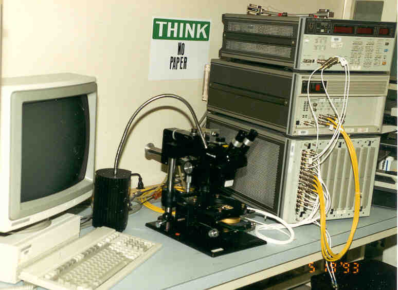
This system combined a precision Mettler analytical balance (with glass doors to keep out wind) with an RS-232 interface and a bar code reader. By weighing the tare weight of an empty container and weighing a known number of raw diode chips we could later keep track of the quantity of diodes in the container and do a physical inventory on all the diodes. This replaced a system where an expert would look at the diodes in a glass vial by eye and "estimate" how many were there. The software used a data base language with a custom software link to the balance and the bar codes were printed to end with a carriage return so that the bar code input looked just like a keyboard entry.Photo - HP 4280 C-meter, HP 4142A SMU, HP 3235A switch matrix & Micromanipulato rmanual probe station
Axial Lead Glass Diodes
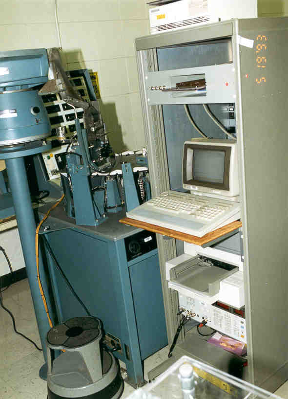
This system used a vibratory hopper to feed bulk diodes into a rotary binner. The computer controlled DC test instruments to decide on the bin number and set the binner to drop the diode in the proper bin.Photo - The tester in the background was obsolete and could no longer be repaired
Microwave Detector Testing for a Satellite Application
This was an upgrade to a system running on an HP workstation written in Rocky Mountain Basic. It measures the D.C. output voltage of a microwave detector with frequency and power as independent variables. An HP power meter is used in the calibration of the system. This system has a repeatability on the order of 0.0x dB.GaAs HBT MMIC chips on wafer & packaged
This was a system to measure DC parameters on GaAs HBT unit amplifiers and ink them. The chips were then returned to the foundry where the wafer was scribed and broken while on a blue membrane and returned to us. We had a Royce Petaluma, CA (Photo) that manually poked out the un-inked chips and automatically placed them into waffle packages. Each wafer had a number of different designs in different locations which needed to be accounted for in the automatic probing and by the packaging operator.Microwave Detectors
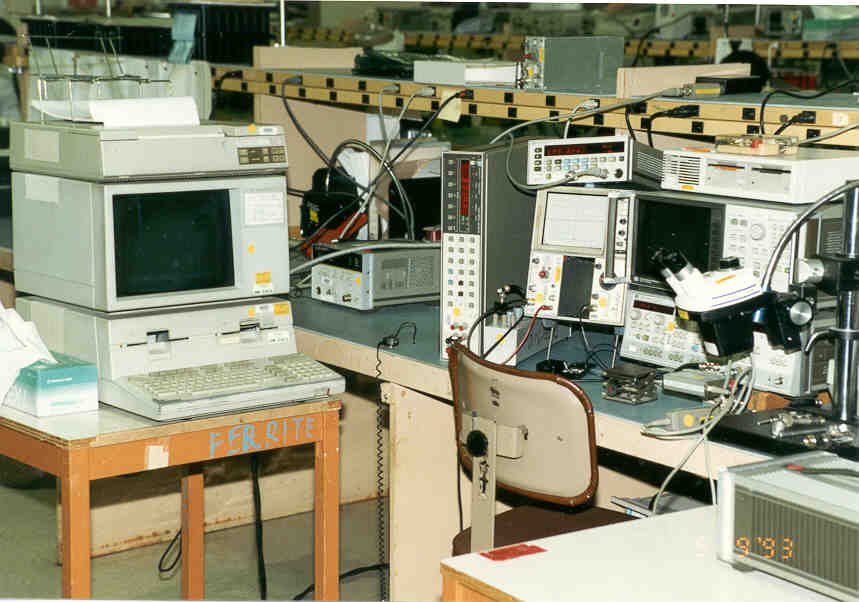
A large number of systems were built for detector testing. The main reason for this was that the voltage out vs. power in transfer curve needed to be tested accurately. Although we had sweep generators that would sweep frequency they had limited capability to sweep power. By using a controller, power meter for calibration, a signal generator to supply the desired frequency and power level, and a DC voltmeter to read the output both the frequency response and transfer curve could be measured accurately. This was a great time saver. Either the HP 438, 436 or 437 Power meter could be used since I had written RMB drivers for all of them. A case of an IVI type driver way before they were developed by NI. The technician would need to input the model number of the head and it's cal data into a file for the program to use.Photo - Many of these systems contained an HP Scalar network analyzer that was part of the automated system using the pass though port so that the system could be run manually or automatically. Also if the program was run with all or part missing it would prompt the operator to connect and configure each equipment. This saves a huge amount of time when a cable became disconnected or broken. The system can be run with or without the scalar analyzer.
In the photo you can see the 438 power meter and in the background the 436 power meter, the software would look at the power meter HP-IB address and figure out which one was being used. The Tek 5110 scope was for manual testing. In the right foreground is an HP microwave power amplifier that was used for power levels higher than could be obtained from the 8350B sweep generator that typically had a .01 to 18 GHz plug-in. The decade box between the Tek scope and one of the supported HP-IB Digital Voltmeters is used to apple a specified load to the detector.
It turns out that the classical cost justification based on conventional accounting fails for many of these systems because of the intangible benefits. For example prior to one system implementation the product was only tested after it was potted, painted and a serial number applied. If the part failed at this point there was an expensive rework cycle that cost both time and money. After the automated test system the part could be quickly checked just prior to potting and fixed quickley.
Oscillator phase noise
Although HP had the 3048 Phase Noise test system it was over kill for our needs. So I made a phase noise test system based on the HP 11729C Carrier Noise Test Set and some related equipment mounted in a half height rack that could be rolled to the bench were phase noise needed to be measured. We cloned this system since it worked well.Mixer scalar and vector parameters plus spurs
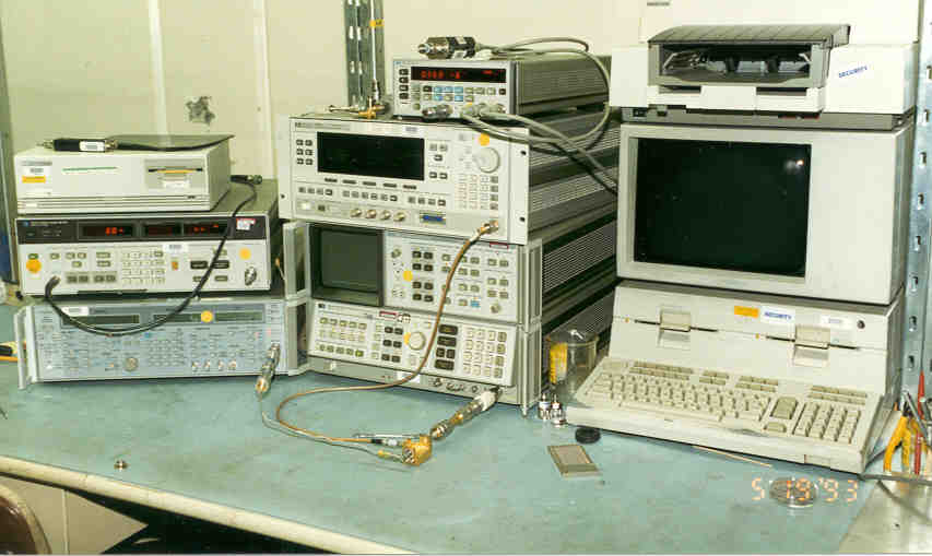
This was the most profitable HP WS Basic system that I built. We were making mixers for a program were the customer specified a long list of spurious products. It took a senior technician a number of days to test all of these. The automated system used synthesizers rather than signal generators. They were both driven from the 10 MHz output from the HP 8566B Spectrum Analyzer (SA). In that way the SA could be tuned to exactly the frequency to be tested rather than sweeping to find the signal. For each spur a number of measurements needed to be made, relative levels calculated and comparison to the limits made for a pass or fail on each test along with a data sheet for each mixer.
4244024 - may be for the HP 8568 & 8566 spectrum analyzers
If you waited for a sweep to make each measurement a lot of time would be wasted. Because the two synthesizers and the spectrum analyzer were all using a common 10 MHz reference the SA could be used in zero span mode. In this mode the CRT shows amplitude variations and so you only needed to allow the sweep to proceed for a small number of pixels then read the marker amplitude.Not only did this system save a huge amount of time and money it changed our way of quoting from charging for the manual testing to charging for the automated testing. This had a tremendous marketing impact because our competitors either were charging for all their spur testing or only doing sample testing. This gave us a big marketing advantage.
Photo - Either Wiltron and HP synthesizers could be used depending on availability. This was done by using modular code and a subprogram that looked for a list of acceptable instruments. Another case of an IVI type driver way before they were developed by NI.
While working at Aertech Bob Mouw invented (US 3,512,090) the Orthostar (tm) Microwave mixer. This was the first doubly balanced mixed that operated above 2 GHz which was the upper limit of the ferrite bead type double balanced mixers like those sold by Mini Circuits. He also invented a wideband detector patent number 3693103 Wide-band Detector for use in Coaxial Transmission Lines Sep 19, 1972 324/95.
Tunnel Diode Testing
Tunnel diodes are also called back diodes when the peak current is below about 1 ma. Back diodes have a number of advantages when used in microwave detectors. In order to characterize the diodes I built a test system that combined RF testing based on an HP 4191A Impedance Analyzer and Keithley voltage and current sources and a Keithley DMM. This system measured all the key parameters on a tunnel diode quickly and without electrocuting the diode.
Photo - The HP 11713 controls the SPDT coax switch, Keithley 220, 230 & 196 for DC and 3488 for DC switching. Tunnel diodes require both voltage and current sources for DC test. In order to measure non-orthogonal parameters like peak and valley voltages requires curve fitting the DC I-V curve.
A problem can occur when testing a Tunnel or Back diode if the DC bias point is in the negative resistance region and the impedance looking out from the diodes point of view is higher than the diode negative impedance and any frequency below the maximum frequency of oscillation, which was many tens of GHz. So, if you want to see a smooth I-V curve a special microwave circuit is needed. Bob Mouw came up with two circuits, one was a radial line made as a sandwich of two aluminum plates with a this sheet of lossy material in between. A tapped hole in the center of the top plate allowed installing the diode between the plates. The DC bias was applied to each plate. A resistor shunted the two plates where the bias wires were connected. The test box contained a bridge circuit that would back out the effect of the shunt resistor so the true I-V curve could be seen on a scope.
The other microwave circuit was a coax line maybe half a foot long where the dielectric was lossy material, but this one was very tricky to make and so not so common.
DLVA transfer curves
A number of systems were made for testing Detector Log Video Amplifiers. These were a combination of a detector and a logarithmic amplifier on the video side of the detector. The testing requirements were similar to those of a detector except there were new parameters to test that were based on a probability of detection. To do these additional tests required modulating the test signal and searching the input power until a predetermined count occurred on a frequency counter.
Photo - We used the Sigma Systems temperature controlled plates in many systems. They took up a lot less room than chambers and because of the intimate thermal contact were quicker to hot or cold temperatures. For cold we used house plumbed liquid nitrogen. We were in Sunnyvale, but in nearby Santa Clara there is a street where LN is a utility so those facilities on that street do not need to have the LN trucked.
Resistor Selector for DLVA temperature compensation
We were behind schedule shipping some DLVAs where they needed to be temperature compensated at cold, room and hot. This required stabilizing at temperature and adjusting a number of resistors to get the desired RF transfer function. A fully automated system was built that would run overnight unattended and print out a table of resistor values for up to four DLVAs on each run. This system was put together quickly and got us back on schedule. It made use of a custom made binary resistor that was controlled by a computer.
Miscellaneous Systems
Quite a number of systems were made to do simple tasks. For example someone needed to measure GaAs transistors and get the data from the HP 8753 Network Analyzer to their computer for design work. I wrote a program to control the 8753 and bias on the transistors so that an operator could just install the transistors and they would get a floppy disk for each transistor. This was a good thing since if the operator made a mistake the expensive transistors were very easy to kill.A home brew HP 8409 automated network analyzer system was put together. It had improved frequency setting by use of an EIP counter locking an HP 8350 sweeper. A DVM was used to measure the X & Y vector signals from the 8414A vector display to avoid the poor quality A/D that was built in. The calibration methods were also upgraded to use more modern methods.
In another case we were making polar discriminators and by using a simple computer program a lot of data could be collected quickly and analyzed for linearity.
In another case power supplies needed to by turned on and off for controlling a stress test.
I worked on a system to test hard disk drive heads in R&D and engineering labs. The system is controlled by HP-IB, RS-232 and IEEE-1394 Firewire interfaces. I am investigating to see if I can control the complete system using a Sony VIAO 505 computer. The slot zero interface driver software now only supports WIN95. When WIN2000 has been released I expect a new Firewire driver to be available.
LabVIEW
Testing micro controller driven EL display for bill changers
A company has an animated Electo Luminescent sign that is driven by a PIC microcontroller. There is an extensive high voltage switching system to drive the various sign elements. The self test involved sequencing the microcontroller though a number of states and measuring the high voltage levels and logic and power supply voltage levels and comparing them to specifications. This system used a Tektronix TDS 3xx scope, Keithley switch matrix, and some custom glue parts.Mil-1553 Cable test system
The customer had integrated the hardware aspects of this system but was up against a time line to get the software running. A LabVIEW program was written in a matter of days to drive the system for testing a family of MIL-1553 cables. The system has worked very well and has been cloned. This system used HP 4339 high resistance meter, the HP 8116 pulse generator and HP 34401 DMM plus a lot of mercury whetted relays driven from a National Instruments 96 bit TTL I/O card.Drivers for HP Microwave Instruments
A company was working on a extensive test system and needed LabVIEW drivers for a number of HP microwave test instruments. These were supplied working and on schedule.Temperature, Humidity, Altitude, Furnace, Random Vibration, Fluid Flow & Level, Hydraulic & Pneumatic Pressure
An Air Force base was testing fiber optic sensors for use on aircraft. There are two aspects to this:This system uses a Tenney combined temperature plus altitude or humidity chamber, a furnace for very high temperatures, a Solarton random vibration system, and a couple of custom built test benches. One for fluid flow or level that used water and a correction factor for JP-4 jet fuel and another for either pneumatic or hydraulic pressure. All the equipment in the lab was controlled from a single Mac computer but only one test station at a time. I wrote the LabVIEW code on my PC and transferred it to the MAC on floppy disks. This is an example of the cross platform portability of LabVIEW.
- they need the stimulus signals for the sensors for example a hydraulic pressure sensor needs to have pressure applied and the output measured as a functional test
- they also subjected the sensors to environments to see how stable they were. For the hydraulic pressure sensor may be put in a temperature chamber and cycled then retested for function.
The system was controlled in the past using a 286 PC that was getting very old and they wanted to use the MAC on their network in order to match what they were doing in other labs in the same section. One aspect that we changed was to stop using an obsolete HP pen plotter for output and switch over to using networked printer. Both B&W and color printers were already on their network in rooms very close to this lab. The printers provided higher resolution output than the old plotter.
The Tenney thermal vacuum chamber would not meet the specifications that the Air Force had and after a number of attempts was returned so I didn't write code for it.
Mac<->Modem ..... Modem<->computer<->GP-IB Remote Test Interface
A company that made semiconductor process equipment wanted to have a capability of controlling its equipment form the factory for diagnostics. I wrote a program on their MAC that controlled the system by sending and receiving HP-IB commands over a simple modem. This required converting some special HP-IB characters to ASCII format that the modem could handle. One problem was that the interface card in the MAC could be moved slightly and this would pull the connector partially out of it's socket causing a malfunction.Driver for Stanford Research PRS-10 Rubidium 10 MHz frequency standard
Driver for TCI/BR RCS-5A Chirp Sounder Receiver
Back to Rack and Stack Systems