SATCOM Antennas

© Brooke Clarke 2010 - 2020

Background
UHF
    Dorne & Margolin C152-1-1
Patents
Microwave
Satellites
Links

Background

Two way satellite communications has been around for a long time.  This page was started after acquiring a military UHF circular polarization SATCOM antenna made by Dorne & Margolin.

UHF

Dorne & Margolin C152-1-1

The boom length, including the BNC connector, is just under 20" and does not telescope.  But all the elements are hinged to allow a compact package for shipment.  The tripod legs can be pulled out of the head and folded so they point up and then fed through two holes in the connector box on the back of the antenna making for a very compact package.  Each element has a spring loaded detent mechanism that holds it in place when in the operational position.  These have the feel of a precision machine.
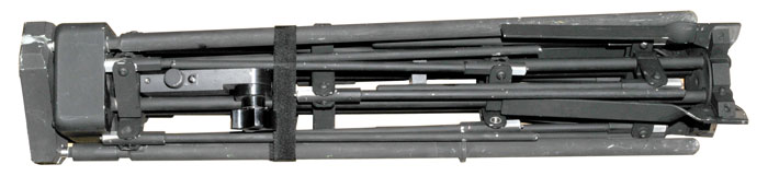
D&M C152-1-1 SATCOM Antenna
Shown in shipping configuration.
Tripod top at left, then electrical box, then antenna.
D&M C152-1-1 SATCOM Antenna
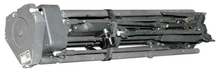
Another view of antenna in ship configuration.

The bottom of the tripod head can be seen.
D&M C152-1-1 SATCOM Antenna
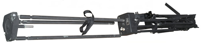
The Tripod has been pulled out of the antenna.
D&M C152-1-1 SATCOM Antenna
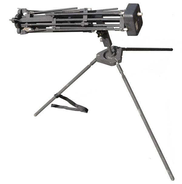
Antenna (still folded for ship) mounted on tripod.
D&M C152-1-1 SATCOM Antenna
Fully deployed.
D&M C152-1-1 SATCOM Antenna
Another view fully deployed.
D&M C152-1-1 SATCOM Antenna
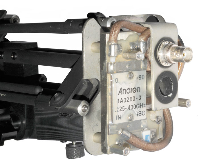
The two top holes are for the tripod legs in the stowed position.

It's not clear what the center hole is used for?  Maybe there's an alternate tripod/mount that uses this hole?  Let me know.
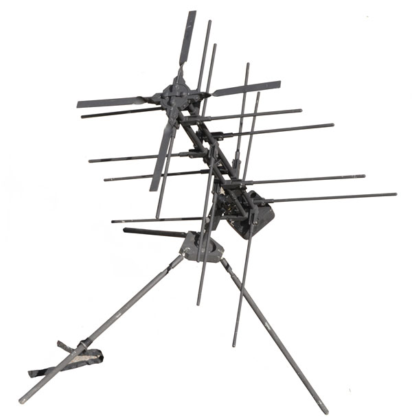
D&M C152-1-1 SATCOM Antenna
Instead of using transmission lines to do the phasing needed to generate circular polarization this antenna uses a 90 degree hybrid coupler.

The BNC connector feeds the IN port and a termination is on the ISOlated port.  The 0 and -90 degree ports feed adjacent tubes in the antenna structure.  This is done by running the coax up the tube and connecting at the front of the antenna where the elements are diagonally connected.

The BNC connector shows a DC short and that's normal since there is a DC path from the IN port to the -90 port which in turn is connected to ground.
D&M C152-1-1 SATCOM Antenna
Front of antenna showing the electrical connection between diagonal supports.

Patents

2501094 Antenna, R.C. Raymond, Mar 21 1950 - has three elements, one direct, one through a cap and one through an inductor to get circular polarization.
2511611 Aperiodic Directive Antenna System, H.A. Wheeler (Hazeltine Res), Jun 13 1950 - Helix
2532428 Elliptical Polarization Electromagnetic Energy Radiation System, C.E. Smith, Dec 5 1950 - using phase to drive the elements to get any desired polarization
3013268 Elliptical-Polarized Logarithmically Periodic Antenna, R.H Du Hamel & F.R. Ore (Collins), Dec 1961 -
Calls:
2278560 Antenna, (Telefunken) Apr 1942 Peters - TV circular polarization
2480154 Aug 1949 Masters (RCA) - TV circular polarization
3039099 Linearly Polarized Spiral Antenna System, - by controling the phase of balanced drive
3059234 Logarithmically Periodic Antenna (Collins) Oct 1962 - coax feed to the front point
3113316 Uni-Directional Circularly Polarized Log Periodic Antenna, (Collins) Dec 1963, 343/792.5 ; 343/795; 343/797; 343/908 -
Calls:
1988434 Antenna System, (Telefunken), Jan 22 1935 - uses "energy transfer line" like the D&M antenna
2192532 Directive Antenna, (RCA), Mar 1940 - Fishbone type
2298449 Antenna, (Bell Labs), Oct 1942 - feed appears to be coax with some elements connected to the shiled and others connected to the center conductor.
3196443 Circularly Polarized Dipole Antenna, (United Shoe Machinery Co), Jul 1965 - sleeve dipoles driven from a coax line
3518690 Boom and Feed Line Construction for Multielement Antenna, (Sylvania), Jun 1970 - low cost unitary boom

Dorne & Margolin

2555857 Antenna System, Arthur Dorne et al (AIL), Jun 5 1951 (filed Nov 1948), - Ram's Horn antenna on top of aircraft
2635187 Broad Band Antenna, Arthur Dorne (Sec of War), Apr 14 1953 (filed Mar 1946), - balanced sellved dipole for aircraft DF
2644090
2658145 Cavity Antenna, Arthur Dorne et al (Sec of War), Nov 3 1953 (filed Jan 7 1946), - slot in aircraft skin
2659003 Antenna Mountable in Small Spaces, Arthur Dorne et al (Sec of War), Nov 10 1953 (filed Apr 1946), - for aircraft
2834959 Antennas, Arthur Dorne (Dorne & Margolin), May 13 1958, - Recesseed slot antenna
2931036 Tunable Slot Antenna Assembly, Arthur Dorne et al (Dorne & Margolin), Mar 29 1960 - 2 parameters are adjustable to match
2949606 Slotted Airfoil Ultra High Frequency Antenna, Arthur Dorne (Dorne & Margolin), Aug 16 1960 -
3276023 Grid Array Antenna,
3951134 Apparatus and method for remotely monitoring and altering brain waves, R.G. Malech (Dorne & Margolin), Apr 20, 1976 -
Signals at 100 & 210 MHz are sent to the brain and the signal at 110 MHz is received and demodulated to sense brain activity.
The demodulated signal can be used to modulate the 100 and/or 210 Mhz signals thus altering the brain signals.
5453753
Mechanically steerable modular planar patch array antenna,  John M. Cosenza et al (Dorne & Margolin, Inc.), Sep 26, 1995 - satcom antenna on Az-El mount
5650792 Combination GPS and VHF antenna,  Shaun G. Moore et al (Dorne & Margolin, Inc.), Jul 22, 1997,
5673052 Near-field focused antenna,  John M. Cosenza et al (Dorne & Margolin, Inc.), Sep 30, 1997 - railroad application
5697583 Radio frequency coupler for communication between adjacent railway cars,  Michael Kane (Dorne & Margolin, Inc.), Dec 16, 1997
5864318 Composite antenna for cellular and gps communications,  John Cosenza et al (Dorne & Margolin, Inc.), Jan 26, 1999 - cables terminated with BNC and SMA

Microwave Antenna Noise G/T

Most microwave antennas for satellite communications use a parabolic reflector and a feed.  The feed is designed so that it illuminated the reflector with as strong a signal as possible and also so that it does not send any signal that does not intercept the reflector.  Any feed spill over will result in wasted transmit power and increased noise when receiving.  The noise increase is because the dirt is at ambient temperature but the sky temperature at microwave frequencies is almost zero Kelvin. 

For reception the figure of merit is G/T where G is the antenna gain and T in the noise temperature.

When C-band satellite first came out it was the way cable TV head end systems got the programming to feed the cable.  So if you put up a medium sized (8 to 20 foot diameter) dish at your house you could watch cable movies for free.  That lasted for a number of years and then they added encryption to prevent the free movies.  I'd estimate that 99% of those dishes were made with an f/d (Focal Length / diameter) ratio of about 0.45 since that provided the highest gain.  But that was a mistake since for the lowest G/T the f/d should be more like 0.3 (i.e. a deeper dish, not as flat as the 0.45 f/d type).

The 10 foot spun aluminum dish I got from the Stanford radio astronomy site in Portola Valley (the other side of 280 from the big dish) had an f/d of 0.3 and outperformed larger dishes that had a 0.45 f/d.

Modern Ku-band satellite antennas use an orange peal dish shape with a offset feed.  The C-band dishes were round and had a centered feed.  The offset feed eliminates the problem of the feed blocking some of the dish area which reduces the gain and adds noise.  But you need to take into account the reflection angle.  My first Ku-band antenna was improperly installed and I've seen other Ku-band antennas with the same problem.  To see it look at the lower antenna mounted on the wall and whose beam hits the metal gutter at:

The Free To Air antenna is round, but it has an offset feed.

Satellites

The SBIR satellites was in the news recently in relation to the shoot down of PS752 (Wiki).
The missile launches were detected from satellites.
Reference: Space-Based Early Warning: From MIDAS to DSP to SBIRS - Wiki: MIDAS, DSP, SBIRS

Links

Trivec - makes satcom antennas

Back to Brooke's Products for Sale, PRC68, Alphabetical Index of web pages, Home web page

[an error occurred while processing this directive] page created 17 Jun 2010.