A friend mentioned that he had this
in his garage and would I like to have it. Here it is.
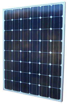
Solar Panel
Parameter
|
Spec
|
Voc
|
30.96 V
|
Isc
|
8.81 A
|
Vpmax
|
22.84
|
Ipmax
|
7.67
|
Ppmax1
|
175 W
|
# of Cells
|
6 * 8 =
48
|
1000 x 1314 x 50 mm (39 1/4 W x 51 3/4 H x 2" T)
Note 1 - Ppmax is Vpmax * Ipmax, not an actual power. The
actual power will be less than this value.
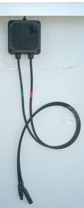
On the back of the solar panel are a couple of wires, one with a
socket termination and the other with a plug termination.
Looks as if you could have gotten ready made cables with matching
terminating connectors to make it easier to install the
system. It's probable that when two panels are arranged side
by side that you can connect them in series using just the cables
on the back of the panel.
Need to find a place where it will not be shaded by all the trees.
The rated output only applies when the panel is getting full
summer Sun. At other times of the year the output will be
lower, even when the panel is aimed directly at the Sun because
the path through the atmosphere is longer and so less light gets
to the panel.
Note that the current into a short circuit is directly
proportional to the intensity of the light falling on a Silicon
diode. One of the things that can be done by a power point
tracking controller is to short the panel and measure the
current. This is done for some number of micro seconds to
get an idea of how bright the Sun is. Knowing the short
current current the controller knows what amount of power is
available. Some controllers do this very often so that they
can track as clouds reduce the light to the panel.
13 Feb 2009 - It's been raining for a number of days.
Checked current output from main panel while raining, facing the
house in near vertical position and got 200 ma into Fluke 87 DMM
in Amps mode.
24 Feb 2009 - 11:45 am 63° F = 7.45 Amps seems to be the peak by
manually tilting and pointing the panel. Need to get the
Electronic Load connected and plot the I-V curve next.
13 Mar 2009 - 12:20 am 63.3° F = 7.83 Amps.
Weston 594 Photronic light
meter into ma current mode of Fluke DMM = 163 ma.
Load Testing
Using
EL1132 Electronic Load
Outside air temp 81 deg F
Weston 594 about 50 ma
Amprobe
LM631A 10940 foot candels
21 July 2010 10:15 am
Not pointed at Sun
Volts
|
Amps
|
Watts
|
25.08
|
0
|
0
|
24.57
|
0.505
|
12.4
|
24.06
|
1.014
|
24.4
|
22.92
|
2.012
|
46.1
|
21.5
|
3.005
|
64.6
|
18.86
|
3.997
|
75.4
|
10.44
|
4.511
|
47.0
|
0.072
|
4.95
|
00.4
|
Aimed at Sun
| Volts |
Amps |
Watts |
25.44
|
0
|
0
|
24.52
|
1.012
|
21.8
|
23.58
|
2.011
|
47.4
|
22.54
|
3.005
|
67.7
|
21.35
|
3.997
|
85.3
|
19.87
|
4.997
|
99.3
|
17.22
|
6.121
|
105.4
|
10.5
|
7.1
|
74.6
|
10:30 am aimed at Sun, resistor load mode of EL1132
Ohms
|
Volts
|
Amps
|
Watts
|
11.6
|
27.27
|
2.351
|
64.1
|
7.7
|
21.76
|
2.842
|
61.8
|
5.9
|
20.97
|
3.553
|
74.5
|
4.9
|
20.26
|
4.136
|
83.8
|
3.9
|
19.21
|
4.901
|
94.1
|
3.0
|
17.41
|
5.866
|
102.1
|
2.0
|
13.71
|
6.922
|
94.9
|
You can see that the load for maximum power changes quite a bit so
any fixed load will waste some power. Hence the need for a
Maximum Power Point Tracking (MPPT) electronics package.
12:00 noon PDT
104 deg F
| Volts |
Amps |
Watts |
24.07
|
0
|
0
|
23.16
|
1.012
|
23.4
|
22.22
|
2.011
|
44.7
|
21.19
|
3.003
|
63.6
|
20.01
|
3.995
|
79.9
|
18.51
|
4.995
|
92.5
|
15.64
|
6.103
|
95.5
|
5.3
|
7.105
|
37.7
|
1:00 pm PDT
103 deg F
Volts
|
Amps
|
Watts
|
23.8
|
0
|
0
|
22.92
|
1.012
|
46.1
|
21.94
|
2.011
|
44.1
|
20.87
|
3.005
|
62.7
|
19.62
|
3.995
|
78.4
|
17.64
|
4.995
|
88.1
|
9.212
|
6.103
|
56.2
|
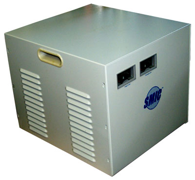
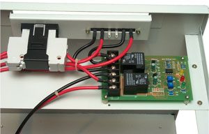
Battery Box & Charge Controller
Uses couple of 14 V automotive
relays and has an 8 pin IC marked HA17393 which is a dual
voltage comparator. There are three LEDs (Yellow, Red
& Green) but they can not be seen when the lid is on the
box. There may be a transistor and diodes, but no
switching mode charge controller. So the function seems to
be disconnecting the panel from the batteries at night or when
the panel voltage is below the battery voltage.
A modern charge controller will adjust the load on the panel so
that it's near the maximum power point even though that is not
the actual load it is supplying.
Maximum Power Point controllers come in many flavors that have
different capabilities, it's a subject of many patents.
This may be the same as the
YY-12-12.
350 x 380 x 300 mm (14 x 15 x 12")
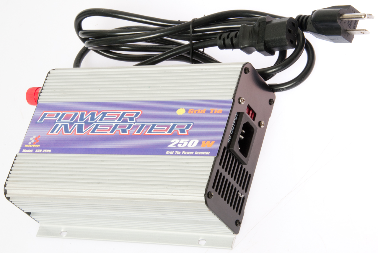
Enphase Energy
- makes a small Maximum Power Point Tracking Utility Intertie
Inverter designed for use on a single solar panel. About
$200 per unit. Intended for use with many panels where
each panel does not need to be oriented the same and where there
can be differences between panels or light falling on the
panels. The controller is about $1400 that's required if
you want to sell the electricity back to the utility. This
also may require a minimum of 1600 Watts system capacity.
Wiki:
Solar
micro-inverter
Two each 65 AH Gel Cell type batteries are recommended wired in
parallel ( i.e. a 130 AH 12 V battery).
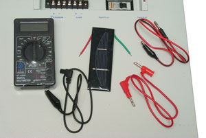
DMM & Calibrated Solar Cell
The idea is to measure the
incoming flux at the user's location and time of year and at the
same time measure the panel short current output.
The Date, Time and temperature for each measurement are also
requested.
Cables
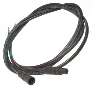
A couple of
cables are supplied that have connectors on one end that match
those on the back of the panel.
The other end of the cables has banana plug connectors that will
plug into the DMM to allow measuring the panel output voltage and
current (although not at the same time).
The female connector (lower left) is marked:
+
ZJRH
05-1
TUV
The Male connector is marked:
-
ZJRH
05-1
TUV
The wire is marked:
TUV 2 PIG 1169 1x4.0mm
2
ZJRH Cixi Renhe Photovolaic Electrical Appliance
Co. Ltd.
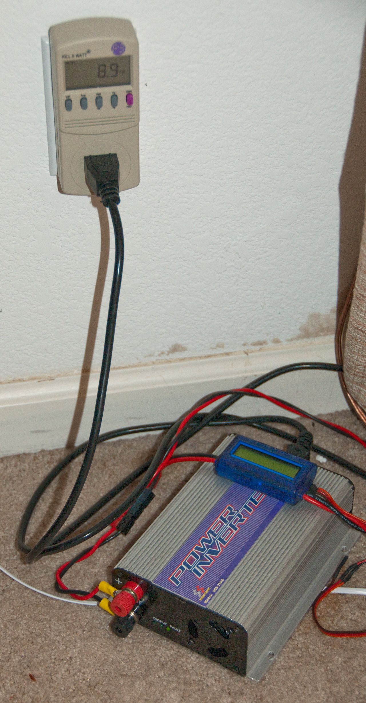
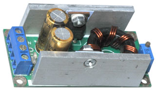
Switching Mode Power Supply (SMPS)
There was a problem in getting a Maximum Power Point Tracking
(MPPT) unit for this particular panel because it's output voltage
exceeds the spec on the unit I wanted to get. A way around
this is to feed the panel output to a SMPS that's rated to take
the possible range of panel voltages and then use it's output to
feed a MPPT unit. That was my motivation for buying this
unit which was listed on eBay (seller: wholesell-aa) as:
DC IN 10-32 OUT 12-35V adjustable converter Module Z
and specified:
Output power: natural cooling 100W
(MAX), strengthening cooling 150W (MAX) real power
Conversion efficiency: 94% (Under
Input 19V 2.5A output 16V) For reference only
These specs are for a higher power than my panel can generate
(about 100 Watts) at my location (it might make more power at the
equator).
Note that as the Sun angle & brightness (clouds) cause the
panel output to fluctuate, this module will try to maintain the
output voltage constant. Although not the same aa power
tracking I expect it's much better than making a direct connection
between the panel and a load. It's now summer and an
interesting load may be a 12 VDC fan, like those attached directly
to automotive radiators.
2015 Update
The
Moringstar
SunSaver MPPT should work with this panel.
Unfortunately these cost over $200.
These are available as integrated
units in the $200 to $400 range. But it may be possible to
use a 12 Volt automotive fan designed to be zip tied to the back
of a radiator. These come in different sizes (diameters) and
have different current requirements. The data from eBay
sellers is mostly missing or inconsistant between sellers, but
this table gives an idea.
Dia.
|
Amps
|
Watts
|
CFM
|
SFP=1
Watts
|
Calc
SPF
|
6"
|
4.8
|
58
|
300
|
14
|
0.19
|
7"
|
6.7
|
80
|
850
|
40
|
0.09
|
9"
|
6.7
|
80
|
1000
|
47
|
0.08
|
10"
|
6.7
|
80
|
1200
|
57
|
0.07
|
12"
|
6.7
|
80
|
1250
|
59
|
0.06
|
14"
|
12
|
144
|
1200
|
57
|
0.12
|
16"
|
14
|
168
|
1600
|
76
|
0.48
|
The 7, 9, 10 & 12" fans all seem to draw the same power, but a
larger diameter fan moves more air.
The 12" fan running seems to be specified at 12V & 6.7 Amps or
80 Watts
Theory
The Specific Fan Power (Wiki:
SFP)
varies between 0.8 (probably these fans) and 2.5
Watts/litre/second (commercial air handling systems).
1 W/L/S = 0.353 Watts/Cubic Foott/second = 21.18 Watts/CF/Minute =
21.18 Watts per CFM.
These seem to be very inefficient fans. There may be a
better choice of fan type. If you know of one
let me know what it is.
Got this in June 2015 as a
demiled foldable solar panel. It's had the label cut off and
the output wires cut off back in the fabric. The wires are
plastic coated and laminated into the fabric so it is not a simple
matter to make a good electrical connection. By using a
large soldering iron to heat up the plastic that surrounds the
wire I think I have remade the electrical connections.
Near the end of the day with the Sun low in the sky the open
circuit voltage is 43 VDC, but when I try to measure the short
circuit current do not get any current. It's as if there's a
very high resistance in the circuit, maybe my wire splice is not
very good? Need to check some resistances along the wires.
[an error occurred while processing this directive] page created 3 Feb
2009