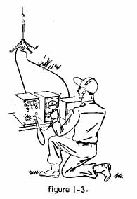
Radio Receiving Sets AN/TRQ-23 & AN/TRQ-30
Antenna Group OE-4/GR
AS-2360 Series Loop Antennas
Table of Antennas &
Receivers
Equipment Descriptions
TG-177/GR
Ant Drive
TG-176/GR
Shelter Ant Mount
IP740/GR
Azimuth Indicator
C-6183/GR
Antenna control
AS-2360
Loop Antenna
AS-2364
Loop Antenna
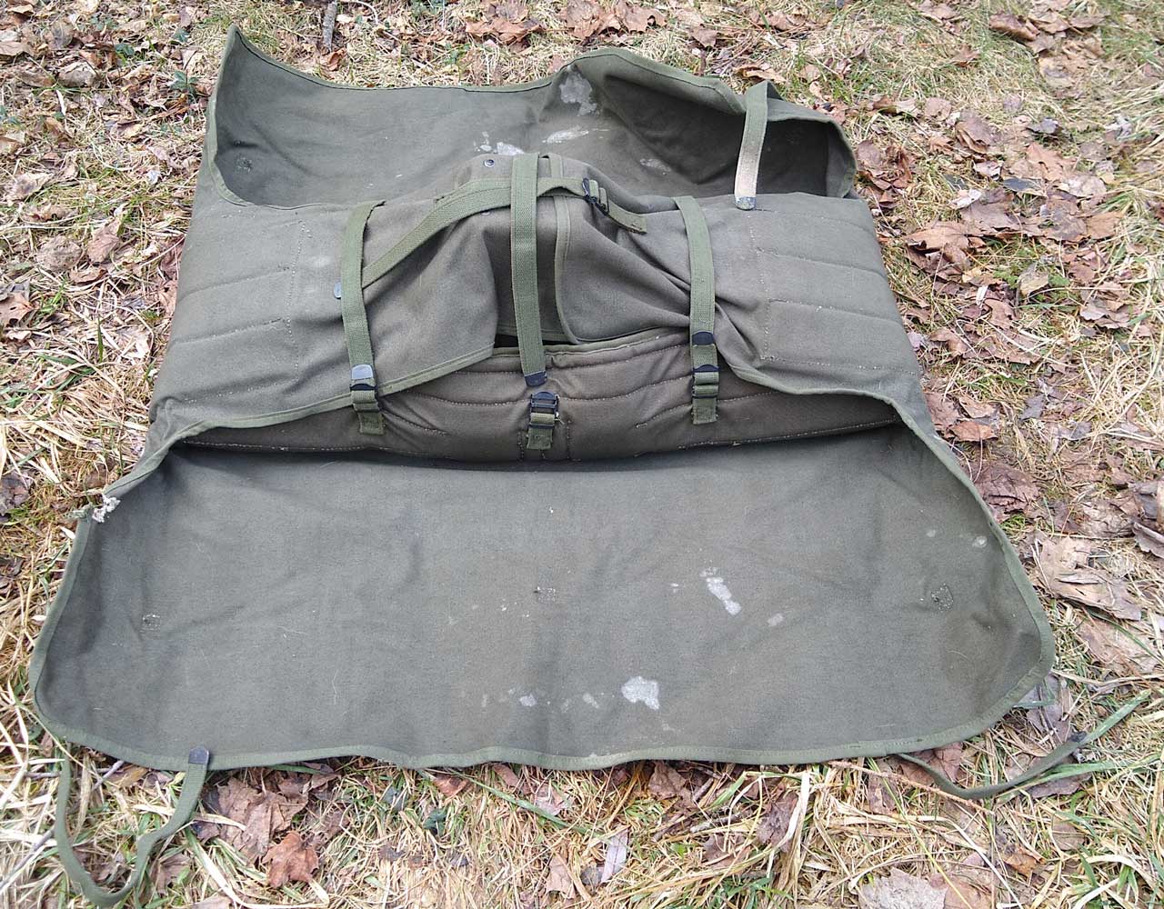
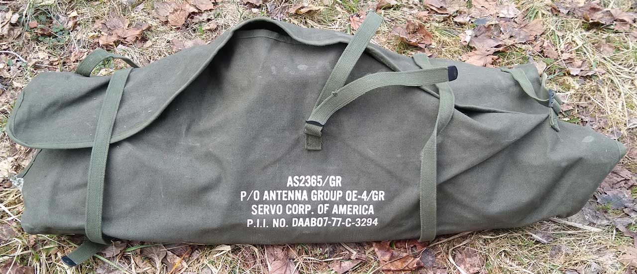
AS-2365 H-Adcock Antenna
Antenna
Group OE-4/GR
R-901
Receiver
TRQ-30
URR-69, URR-70 & URR-71 Man portable
intercept receivers
R-1518/URR-71 Receiver
TRQ-23 Documents
Frequency Coverage, Antennas &
Receivers
|
Band #
|
Freq MHz
|
Antenna
|
Type
|
Receiver
|
| 1 |
0.53 - 1.1 |
AS-2360/GR 0.53 - 10 (20.5)
MHz
Servo p/n 7040-LA |
loop |
R-901/GR |
| 2 |
1.1 - 2.3 |
"
|
" |
R-901/GR |
| 3 |
2.3 - 4.8 |
"
|
" |
R-901/GR |
| 4 |
4.6 - 9.9 |
"
|
" |
R-901/GR |
| 5 |
9.5 - 20 |
AS-2361/GR 10 - 20 MHz
Servo p/n 7040-LB
AS-2360/GR 0.53 - 10 (20.5) MHz |
loop |
R-901/GR
0.536 - 20.5 MHz |
| 6 |
20 - 33 |
AS-2362/GR 19.5 - 33 MHz
Servo p/n 7040-LC |
loop |
? |
| 7 |
31 - 56 |
AS-2363/GR 31 - 56 MHz
Servo p/n 7040-LD |
loop |
normal mil rcvrs
R-1518/TRQ-30
|
| 8 |
55 - 101 |
AS-2364/GR 55 - 101 MHz
Servo p/n 7040-LE
AS-2365/GR 95 - 210 MHz
Servo p/n 7040-HAD |
loop
H-Adcock
|
R-902/GR
95 - 405 MHz
R-1518
|
| no # |
190 - 1050 |
AS-2365/GR 95 - 210 MHz
AS-2366/GR 190 - 1050 MHz |
H-Adcock
Log Periodic |
R-902/GR
? |
no #
|
382 - 1020
|
?
|
?
|
R-903(XE-2)/PRD
|
The current version of this system may be
Equipment Descriptions
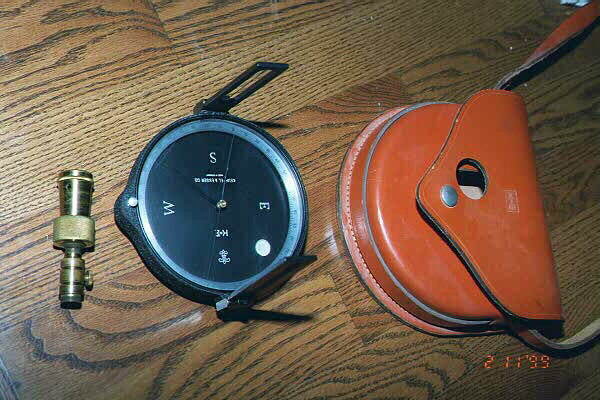
TG-177/GR Portable Antenna Drive -
Tripod mount WANTED TO BUY
In this drawing you can see:
- Portable Antenna Drive TG-177/GR
- Tripod (Legs Electrical Equipment) MX-6334/GR
- Compass
J23
15 RPM nominal (clutch energized) 24 VDC @ 300 mA
150 RPM (clutch de-energized)
18 - 32 VDC
Rotation by means of a 24 VDC motor with a 24 VDC clutch.
Resolver reads back antenna
position.
TG-176/GR Fixed
Antenna Drive - Shelter mount WANTED TO
BUY
Rotates at 60 PRM (1 rev per second).
24 VDC @ 375 mA. to azimuth DC motor (pin L and ground pin x)
Resolver (R1: pin: U; S1: pin S, R2: pin V=pin W=R3; R4: pin T)
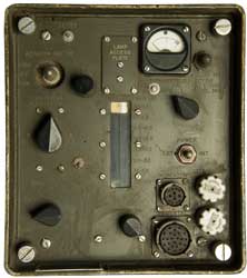
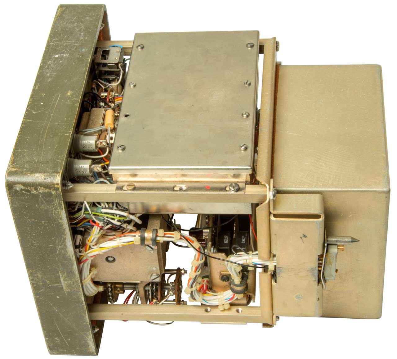
IP740/GR Azimuth Indicator - CRT
based
Since the continuous rotation speed can be up to 150
RPM a CRT type indicator will have a much longer life than a
mechanical indicator. The antenna pattern can be seen on
the screen and the null direction read out to within 2 degrees.
There has been a modification that disconnects the active
wire from Diode Input connector on the Front panel and adds a
BNC(f) connector to the rear panel, a pot on the rear panel,
Red & Black wires coming out the rear panel and a Sense
push button on the front panel (maybe to replace a momentary
rotary switch or diode connector?).
On the Front and Rear panel there are a 4 pin Power Input
connector (ITT Canon 1S13114E8-4P)
and also a pair of Control Unit connectors (Burndy 14-12P)
with 8 small pins and 4 large pins.
The name plate says:
Indicator, Azimuth
IP-740/GR
Serial No. 47
Servo Corporation of America
PII No. DAAB05-67-C-2337
U.S.
Battery to Indicator Cable Assembly, CX-11950/U (5'0") must
have an ITT Canon 1S13114E8-4S connector.
C-6183/GR Antenna control
Band Switch
There is a band switch with "sync" and band numbers 1 through
8 (see below table). The antennas all have provision for
8 band positions, but only some are used in any single
antenna. The AS-2360 supports band numbers 1 through
5. The bands are changed by means of a 12 position
rotary solenoid in the antenna assembly. In position 6
the coil of antenna sense relay (K1) is connected to the
"Sense" line pulling the line up to +36 volts (B+) allowing
the control unit to synchronize (SYNC) thus learning that the
solenoid is on step # 6. I expect that when the antenna
control band switch is placed in "SYNC" the solenoid rotates
until position 6 where it stops. The solenoid only
rotates in one direction 30 degrees per step.
Band
|
Low
MHz
|
Hi
MHz
|
1
|
0.53
|
1.15
|
2
|
1.10
|
2.35
|
3
|
2.25
|
4.80
|
4
|
4.60
|
9.90
|
5
|
9.50
|
20.5
|
6
|
19.5
|
33.0
|
7
|
31.0
|
56.0
|
8
|
55.0
|
101
|
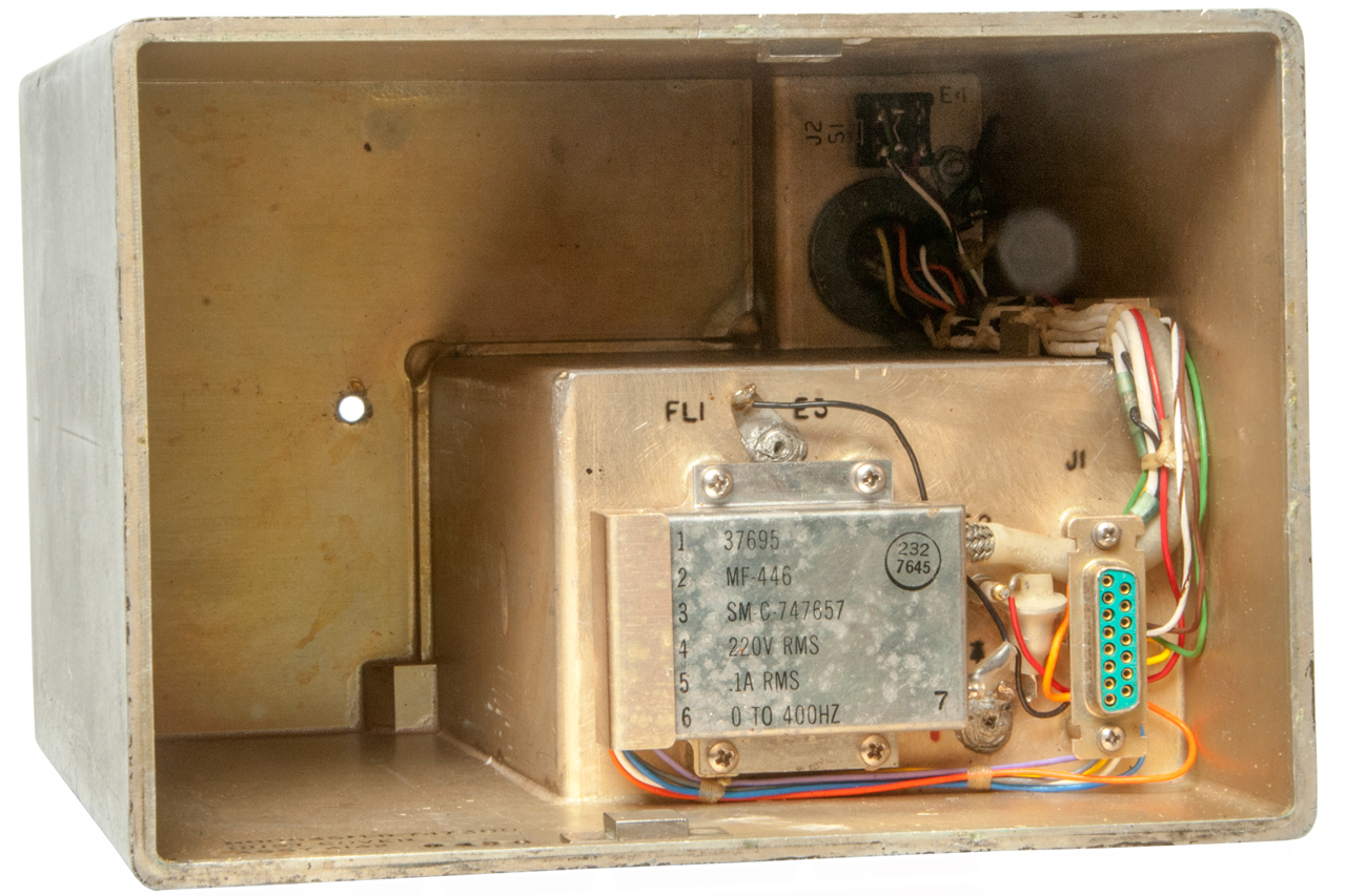
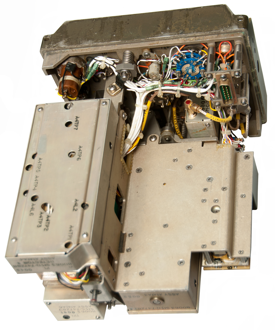
Photos
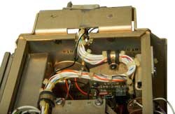
The Mystery Circuit
(Fig 8 and Fig 9
below). Battery Boxes.
This is the internal battery consisting of four each BA-408, 6V
batteries with Octal sockets.
The four tube bases are labeled BT1 through BT4.
SM-D-64 33 95 - my be the drawing for this assembly.
The 4 devices are wired in series.
? - Orange - BT2 - Black - BT1 - White - BT3 - Orange - BT4 -
Black - J5
BA-408 might be 2.5" x 2.5" on the face with the Octal socket
and stand 3.5" tall.
That space probably would hold 4 each "D" cells.
Internal batteries are only needed if the IP-740 is not part of
the equipment setup.
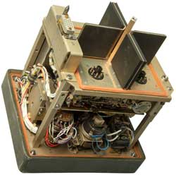
Fig 1 Front
|
Fig 2 Labels
 |
Fig 3 Back
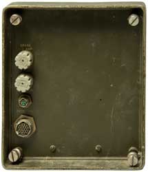 |
Fig 4 Inside Back Cover
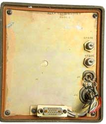 |
Fig 5 Inside Back of Chassis
 |
Fig 6 Left & Top Inside
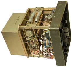 |
Fig 7 Right & Bottom Inside
The Rear connector bracket is bent.
 |
Fig 8 Mystery
Circuit= battery boxes for BA-408: 6V
|
Fig 9 Other
side of Mystery Circuit
|
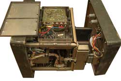
Fig 10 Front & Back mated w/o cover.
Internal lid opened.
 |
|
|
The antenna can be rotated continuously at speeds
ranging from 15 RPM to 150 RPM (depending on which mount is
used) or can be manually turned CW or CCW.
The Front panel has connectors for the Indicator (Bendix
PT02E-14-12S) and Pedestal (Bendix PT02E-20-24S) .
Indicator (Front Panel)
Bendix 14-12; 8 small & 4 larger sockets
Pedestal (Front Panel)
Bendix 20-24; 24 small sockets
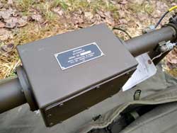
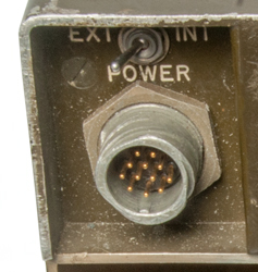
The Rear panel has connectors for Power In (ITT Canon
1S13114E8-4S) and Pedestal (ITT Canon MS3114E14-19S).
Why is the rear Pedestal connector different than the Front
panel Pedestal connector?
Power In (Rear Panel)
Bendix; 4 small sockets
Pedestal (Rear Panel)
MS3114E14-19S2; 19 small sockets
The name plate says:
Control, Antenna
C-6183/GR
Serial No. 106 A
Servo Corporation of America
PII No. DAAB07-77-C-3294
U.S.
Control to Indicator Cable Assembly, CX-11952/U (5'0") looks like a 12 wire with male pins on one
end and female pins on the other end. Both connector
shells are MS3114E14 type.
Battery to Control Cable must have an ITT Canon 1S13114E8-4P
connector.
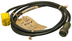
Control to Drive Cable Assembly CX-11953/U (100'0") WANTED TO BUY
AS-2360 Loop Antenna
Description from Fair Radio eBay
auction:
AS-2360 Loop Antenna .53 Mhz to
10 Mhz, usable to 20.5 Mhz.
Impedance 50 ohms
Null depth 25 db, bearing error less than 2 degrees.
Originally part of TRQ-23 radio receiving set.
The base of the loop contains a loop cathode follower with
Varactor diode for tuning, two RF amplifiers, and an output
cathode follower using 4/6612 tubes which require 36 v B+,
1.1v filament.
Tuning voltage 0-102 vdc, gain voltage 0-37 vdc, sense relay
24 vdc.
Comes with canvas bag, sense antenna (not pictured), connector
for antenna, schematic.
Not tested, used good physical condition. AS IS.
Approx size 6.4 x 26.2 x 61.8 (with sense antenna )
From the Fair Radio - 2020
October Sale web page:
"Loop Antenna .53 Mhz to 10 Mhz useable to 20.5 Mhz.
Impedance 50 ohms Null depth 25 db bearing error less
than 2 degrees. Originally part of TRQ-23 radio
receiving set. The base of the loop contains a loop
cathode follower with varactor diode for tuning two rf
amplifiers and an output cathode follower using 4/6612
tubes which require 36 v B+ 1.1v filament. Tuning
voltage 0-102 vdc gain voltage 0-37 vdc sense relay 24
vdc. Comes with canvas bag. 6.4×26.2×61.8 30 lbs sh.
Used" |
It has 6 separate loop windings that can be connected
by relays to operate in band numbers 1 through 5. It also
has a Varactor diode to allow resonating the antenna. The
R-901/GR and R-902/GR receivers output the diode tuning voltage
which is passed through the antenna indicator unit then the
control unit and finally to the antenna. Schematic.dwf (get the Autodesk free Volo
viewer to see this) and the corresponding parts list.
Connections to the AS-2360 (and probably all the other loops
are the same)
|
Pin #
|
Name
|
Description
|
|
1
|
Relay Ground |
? return for pin 5, big current pulses? |
|
2
|
Loop Gain |
control voltage to 6612 RF amp screen grids |
|
3
|
Sense |
control voltage activates sense ant & for Sync |
|
4
|
Filament 1.5 VDC |
to drive 4 6612 tubes in parallel
WHAT IS THE VOLTAGE? 1.1 VDC? |
|
5
|
Band switch |
Bipolar pulses to change bands |
|
6
|
Ground |
|
|
7
|
+36 |
B+ for 6612 tubes |
|
8, 9
|
N.C. |
|
|
10
|
Diode Tuning |
0 to +? VDC range for
VA-521A varactor diode? |
|
A1
|
RF |
output coaxial connector (DC blocked) |
Photo of rotary solenoid, 4 deck switch
and resistor board
The 30 deg/step rotary solenoid was made by Ledex
- p/n 128558-001 date code 7913.
From their records the drive voltage is 28 VDC and a 50
millisecond pulse would be long enough to latch.
Remember that the B+ voltage is 36 (see pin # 7 above).
The 12 position, 4 deck rotary switch was made by Grayhill.
The connector on the base of the
AS-2360 (inside the lower tube) is a special DB15(m).
It has a coax connector in the center that has a male shield
and a female center contact.
It may be a Cannon Combo
D but I have not figured out their part numbering
system.
Mouser carries a D-Sub
Mixed Contact Connector and the 152-FM11W1S housing
looks correct.
Page
165 shows these connectors. It's not clear
which of 152-FMX1067, 3067, 0003P or 0003S is the correct coax
insert.
AS-2364 Loop Antenna - Photo
Label: Antenna, AS-2364/GR, Serial
No. 61 A, Servo Corporation of America, PII No.
DAAB07-77-C-3294, U.S.
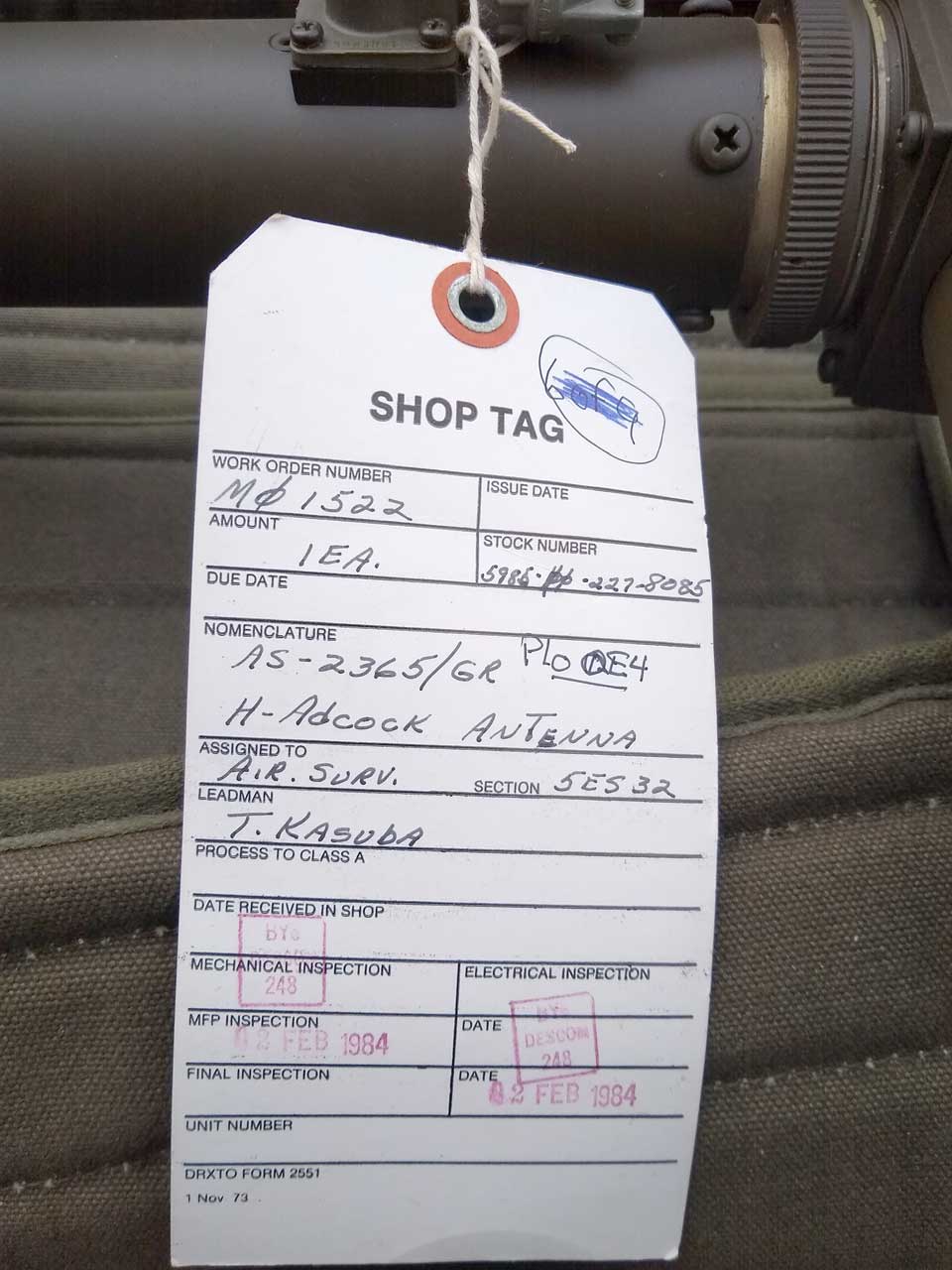
AS-2365 H-Adcock Antenna
2026 March: Photos courtesy of JZ kc3mvl.
Fig 1 Shipping Bag
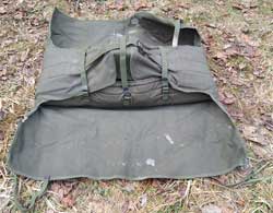 |
Fig 2
AS2365/GR
P/O Antenna Group OE-4/GR
Servo Corp. of America
P.I.I. No. DAAB07-77-C-3294 (1977 contract)
 |
Fig 3 Shipped w/vertical arms separate
from Main body.
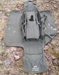 |
Fig 4 "H" after assembling V arms.
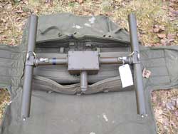 |
Fig 5 Electronics box
|
Fig 6
Stock No.: 5985-00-227-8085
Last Insp: 02 Feb 1988
 |
Fig 7 Connector Shell used to connect
Whip Antennas. Note disk with 4 holes is plastic,
i.e. an insulator.
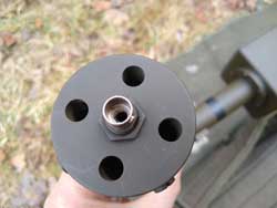 |
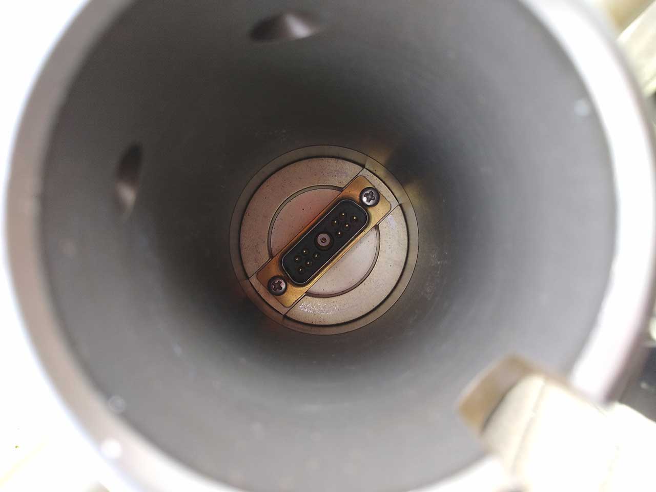
Fig 8 This is the common view looking up
into the central mast of all TRQ-23 antennas.
A DB type connector with 5 mail pins + Coax + 5 mail
pins.
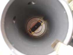 |
Fig 9
Amphenol Coax Relay.
Model: 327-10582-3
SP3T, BNC Connectors, 26VDC Coil
Size: 2.5"~ x 2"d x 2"h
NSN: 5985-00-879-4653
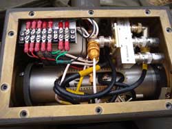 |
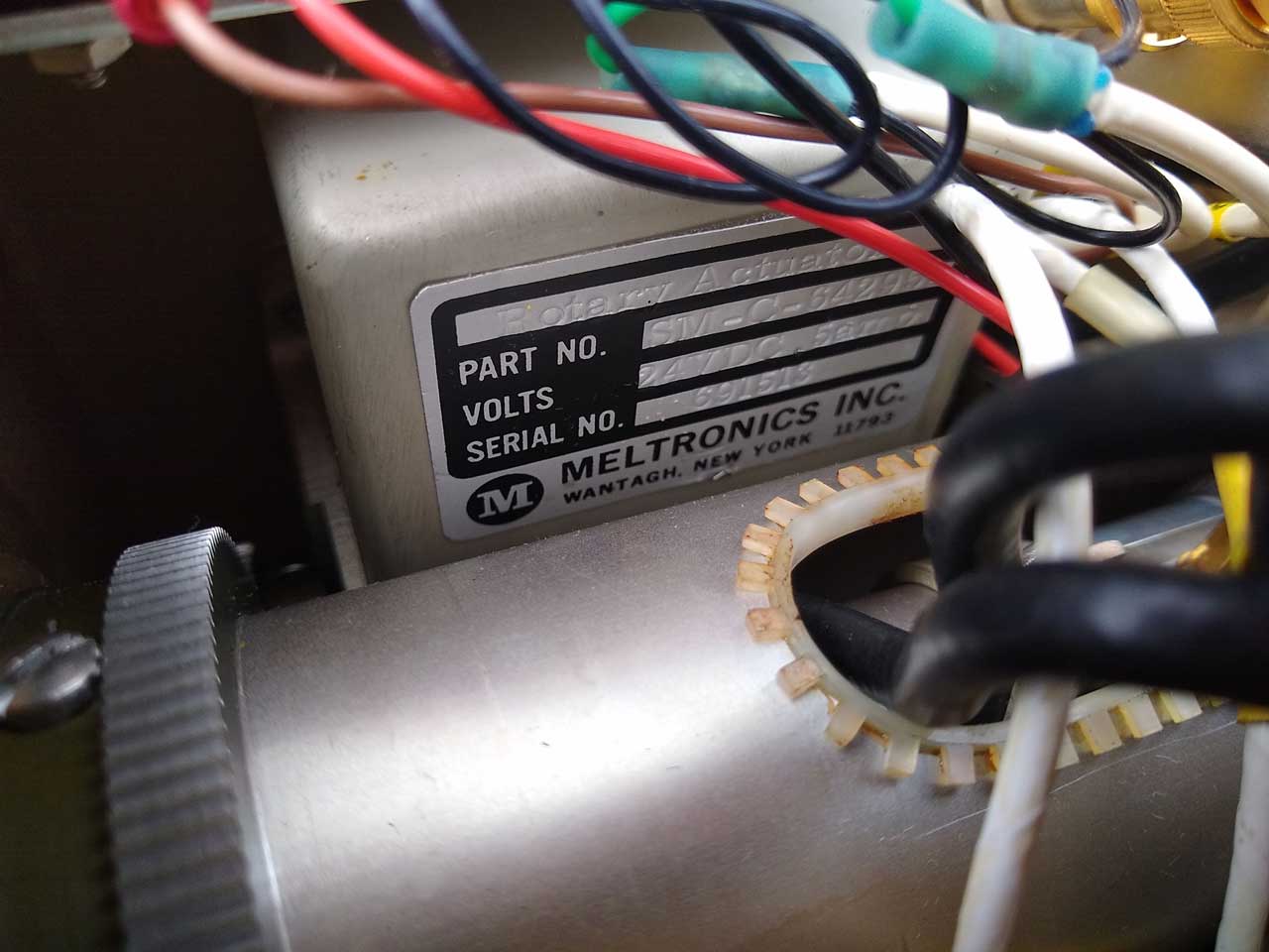
Fig 10
Rotary Actuator - Drives Whip Angle
Part No. SM-C-4295?
Volts: 24 VDC, (.?)5 amp
Serial No. 691513
Meltronics Inc, Wantagh, NY 11793;
 |
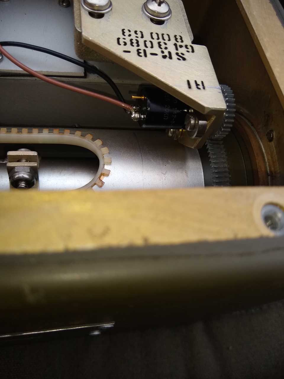
Fig 11 Pot to report whip angle
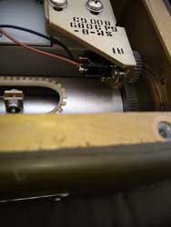 |
Fig 12
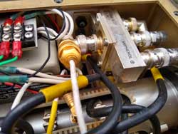 |
Fig 13
|
Fig 14
|
|
|
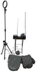
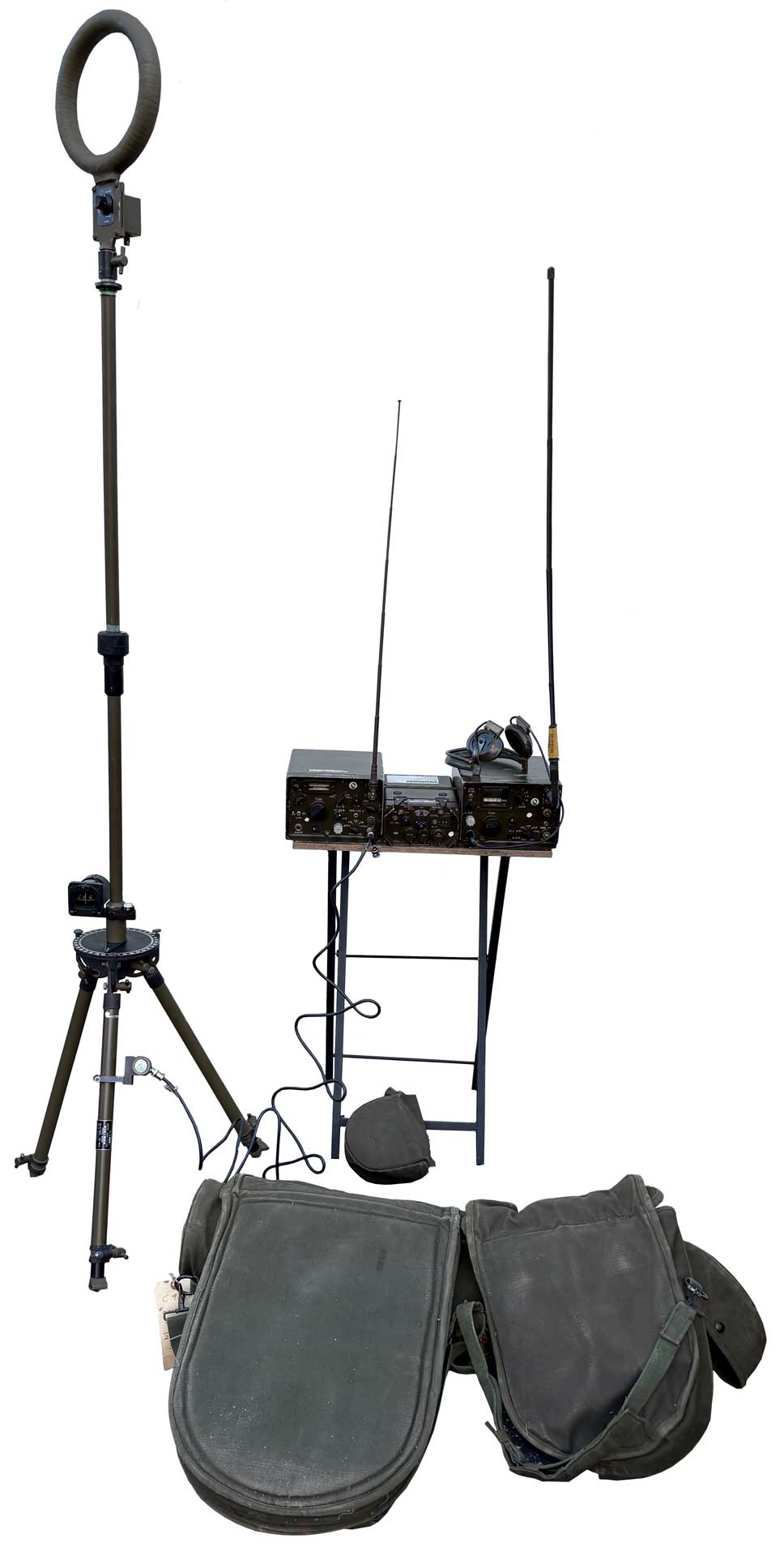
Antenna Group OE-4/GR -
In the above cover drawing for TM 11-5985-360-10
you can see:
- 2 receivers on the left
- antenna control unit C-6183/GR
- IP740/GR Azimuth Indicator on top of the control unit
- TG-177/GR Portable Antenna Drive
- J23 Magnetic Compass
- some cables
made by
Servo Corp who made the
rotator.
NSN 5985-00-227-8115
R-901 Receiver
536 kHz to 20.5 MHz in 5 bands. CW,
MCW and AM modes. 455 kHz IF with 1.5 or 4.0 kHz bandwidth
by mechanical filters. Built in crystal
calibrator. Filaments 1.5 V @ 445 ma, Plates 45 Volts @ 30
ma.
The plate circuit of the third IF amp V1 is fed to a transistor
circuit that generates a negative voltage depending on the
strength of the IF signal to drive the DF display. A
separate circuit is used for the audio output.
TM 11-5820-783-14 Operator's,
Organizational Direct Support, and General Support Maintenance
Manual Radio Receiver R-901/GR, NSN 5820-000-136-4974, 17 Sep
1973, Change 2 -
contact brooke
to buy a pdf version.
In addition there are:
TM 11-5820-783-20P Org Parts Manual
TM 11-5820-783-24P DS Parts Manual
TM 11-5820-783-34P DS & General Parts Manual
TRQ-30
|
AN/TRQ-30 direction finder
radio set includes:
R1218 .5-20 mhz ,
R1518 2-157 mhz,
PNH-7 cassette tape recorder,
AS-1523 hf loop,
AS-1526,27,28 vhf loops,
AB-1110 tripod,
aircraft compass,
signal null meter,
multiple canvas cases,
AS-2887 TNC tape antenna
aftermarket TNC collapsible antenna. |
The Compass mounted on antenna mast is an aircraft
standby compass, not the surveying compass used on
the TRQ-23.
Photo courtesy of Jeff
|
The R-1218 and R-1518 are both part of the TRQ-30 Radio
Receiving Set, see: TM-32-5895-206-10.pdf.
The Radio Receiving Sets AN/TRQ30(V1), AN/TRQ-30(V2), and
AN/TRQ1-30(V4) are backpack transportable radio direction finding
(DF) and
communications intercept units. The three sets have different
capabilities (refer to tables 1-1, 1-2, and 1-3). Each set is
capable of receiving radio signals in a particular range,
recording received keyed or audio range signals, and finding the
azimuth of received signals. Each set is intended for independent
single operator field operation and operator transport between
operating points.
Key elements of the TRQ-30 are: Packboard, R-1218/UR HF receiver,
BA-522/PNH-7 Battery assy, R-1518/UR VHF receiver and AN/PNH-7
(cassette tape) sound recorder/reproducer.
The UNH-16A Cassette Recorder-Reporducer is a newer version. (TM
32-5835-001-10.pdf) It uses the M-104/PNH-4 (modified)
microphone.
The antennas are described in TM_11-5985-352-14.pdf
Antenna Group, Part of Direction Finder Set, AN/TRQ-30(V)1, 2 and
4, July 1977.
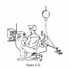
The AB-1110 consists of a tripod, two mast assemblies, 4 support
Nylon cords and an aircraft standby magnetic compass.
The implication is that the tripod and masts are non
magnetic. Note there is no antenna rotator motor, it's an
Armstrong system. The height of the loop on the two masts +
tripod is low enough that the controls at the base of the loop can
be manually operated.
Name
|
Dia.
in.
|
Band 1
MHz
|
Band 2
MHz
|
Band 3
MHz
|
Band 4
MHz
|
Band 5
MHz
|
AS-1523*
|
12-3/16
|
0.515 - 1.2
|
1.03 - 2.6
|
2.03 - 5.3
|
3.83 - 9.4 |
8.46 - 21
|
AS-1526
|
8-11/16
|
19 - 50
|
|
|
|
|
AS-1527
|
5-3/16
|
45 - 100
|
|
|
|
|
AS-1528
|
3-3/4
|
95 - 157.5
|
|
|
|
|
Note *: The AS-1523 has a band switch on the box at it's base.
It's not a remote control system.
2023Oct06: So far I have not seen how the "diode" output from the
radio is used in this manual system. Maybe there was a plan
to add a motorized drive to the antenna system?
2025Sep05: Answer from Jeff. The TRQ-30 uses neither a motor
driven antenna nor a CRT display. The diode output is used
to drive a signal strength meter that's mounted at the
antenna. That's to say the TRQ-30 is a less capable system,
i.e. manual antenna rotation instead of instantaneous bearing
indication.
URR-69, URR-70 & URR-71 Receiver
Systems
These are HF & VHF intercept receivers that are typically
carried on a back pack. They can operate from a dozen "D"
batteries or AC mains.
While these receivers have a "diode" output, it's for use with
some unspecified "external equipment".
The antenna specified under the URR-nn nomenclature is either
not included or a tape whip, which is all that's needed for
interception, and optionally recording, transmissions. But
when integrated into the TRQ-30 signal intercept system a
directional antenna is added. But these antennas are
manually positioned, i.e. not using servo motors.
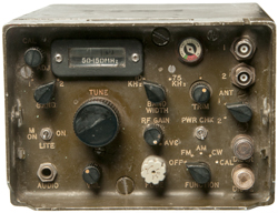
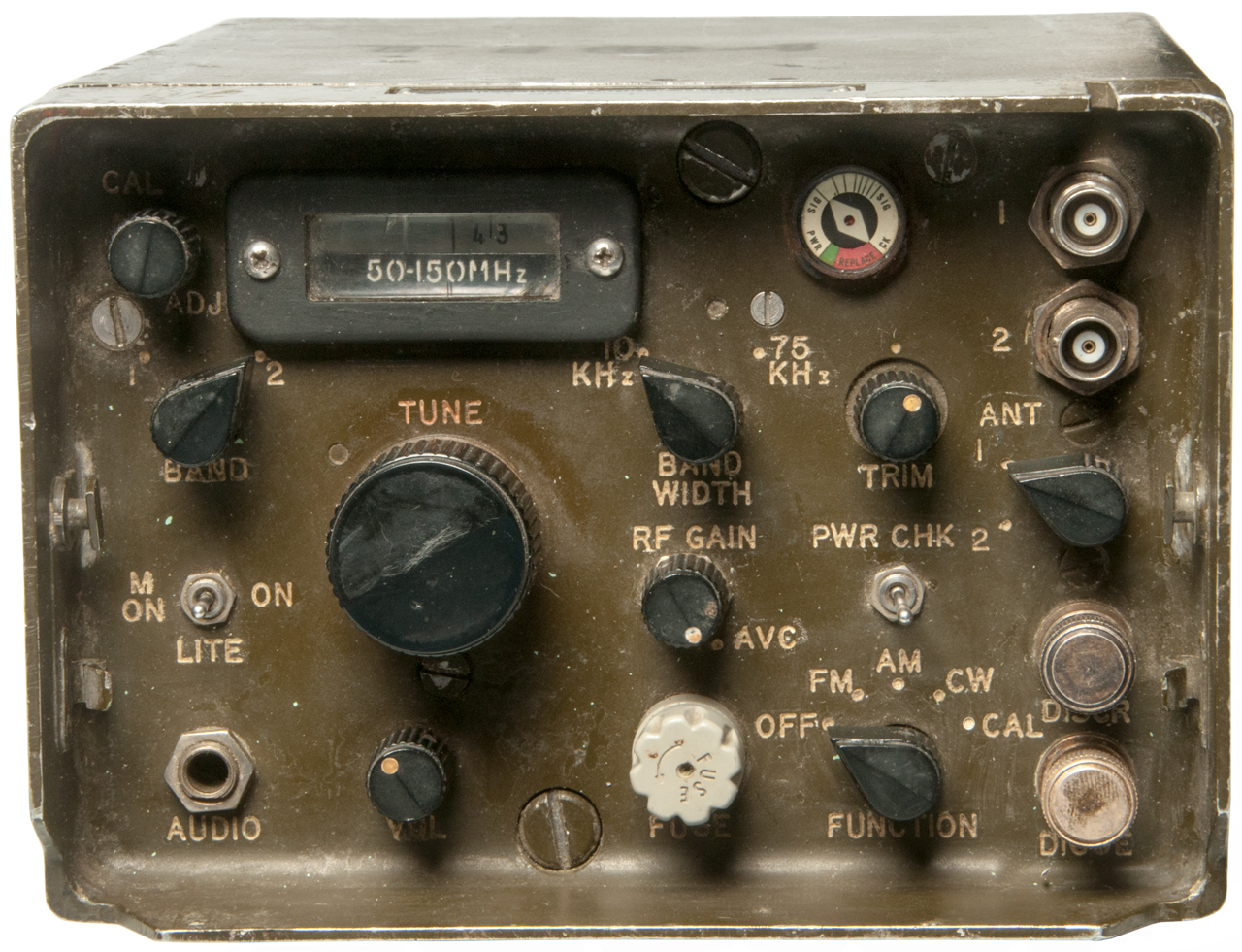
R-1518/URR-71 Receiver
Description
I got this receiver because it has a "DIODE" BNCf connector on
the front panel and that's an indicator that it will work with
the Rotating antennas associated with the TRQ-23. (Also
see Radio Direction
Finding for earlier CRT based DF equipment).
These were used mainly by the US Army to monitor their own
troops to insure compliance with communications security
protocols, but might also be used to gather intelligence from
enemy communications. CAGE Code 80063 is US Army
Communications & Electronics Materiel Readiness Command
Logistics Engineering Dir (CECOM).
Portable receiver, battery (12 ea. "D" cells) or external
110/220 VAC power (50 to 400 Hz), or external 24 VDC power;
19.0 to 157.5 MHz, AM, FM, CW.
Uses AS-2887/UR Tape Whip antenna with TNCm connector attached
to ANT 1 where "Trim" peaks the response;
CW-1005/UR Field carry bag.
ANT2 is for a 50 Ohm Antenna.
Accessories
Headphones, like the H-218/GR with 1/4" phone plug.
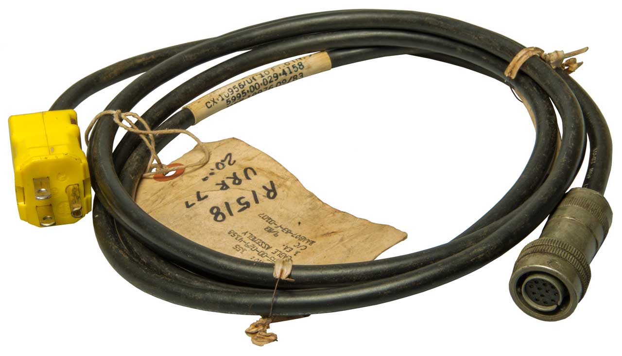
110 VAC Power Cord: CX-10956 p/o Accessory Kit MK-1517/UR
220 VAC Power Cord: CX-10957 p/o Accessory Kit MK-1517/UR
24 VDC Power Cord: CX-???
Power Connector
|
CX-10956/U (10 Ft, 0 In.)
5995-00-029-4158
Mfr 19976 09/83
Line Hot: C-H
Line Neutral: L
Gnd: F
Jumper: A-B-K
The 12 Socket connector is the U-290/U like
used on the CX-4722 Antenna Control Cable
for the MX-6707.
|
Power
J2
|
Function
|
24 VDC
Cable
|
110 VAC
Cable
CX-10956/U |
220 VAC
Cable
CX-10957/U |
J1
DB15
|
A
|
AC in
|
nc
|
A - B -K
|
A - K
|
14
|
B
|
AC in
|
nc |
A - B -K |
B - C
|
7
|
C
|
AC in
|
nc |
C- H - Line
|
B - C
|
5
|
D
|
AGC out
|
nc |
nc |
nc |
9
|
E
|
+24 VDC in
|
E - K
|
nc |
nc |
13
|
F
|
Ground
|
Ground
|
Ground
|
Ground
|
12
|
H
|
AC in
|
nc |
C - H
|
Neutral
|
6
|
J
|
Shield Ground
|
nc |
nc |
nc |
|
K
|
AC in (fuse)
|
K - E
|
A - B -K |
A - K
|
15
|
L
|
AC in (fuse) |
+24
|
Neutral
|
Hot
|
3
|
M
|
Audio Out
|
nc |
nc |
nc |
1
|
N
|
Diode Out
|
nc |
nc |
nc |
8
|
-
|
+18 VDC
Internal Battery
|
- |
- |
- |
4
|
-
|
Dial Light Sw
|
- |
- |
- |
10 00
|
-
|
+ 18V
External Power
|
- |
- |
- |
11
|
Photos
Fig 1
|
Fig 2 Twelve
"D" Cells = 18 VDC
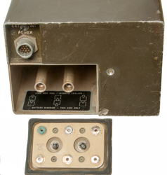 |
Fig 3
 |
Fig 4 CAGE 80063
US Army Communications & Electronics
Materiel Readiness Command Logistics
Engineering Dir (CECOM).
 |
Fig 5
 |
|
R-1518 Manual
TM 11-5820-770-14 Operator's Organizational, Direct
Support, and General Support Maintenance Manual, Receiving Set,
Radio AN/URR-71, NSN: 5820-00-013-8944, Aug 1972, Change 2
TM-32-5895-206-10
TRQ-23 Documents
Manuals
TM 11-5825-242-10 Radio Receiving Set AN/TRQ-23, Dec
1969 (hard copy from Fair Radio)
TM 11-5825-242-24 Organizational, Direct Support, and
General Support Maintenance Manual, Radio Receiving Set
AN/TRQ-23, (NSN: 5820-00-136-4967), June 1975
TM 11-5825-242-25 Limited Coverage, Organizational, DS,
GS and Depot Maintenance Manual, Radio Receiving Set AN/TRQ-23,
Dec 1969
Theory of operation, schematics, test voltages and
resistances.
Battery Table
Battery
|
Equipment
|
Voltage
|
BA-403/U
|
Radio Receivers:
R-901/GR, R-902/GR,
R-744V/PRR
|
1.30 to 1.50
|
BA-408/U
(4 ea D?)
|
Antenna Control
G-6183/GR
|
5 to 6
|
BA-411/U
4 each
|
Battery Box CY-3589/U
|
Total string:
20 to 24
|
BA-415/U
|
Radio Receiver R-902/GR
|
72 to 90
|
BA-418/U
|
Radio Receivers:
R-901/GR, R-902/GR,
R-744V/PRR |
38 to 45
|
BA-30/U
|
Hand Lantern
|
1.25 to 1.50
|
Books
Unlikely Warriors: The Army Security Agency's Secret War in
Vietnam 1961 - 1978, Lonnie M. Logn & Gary B. Blackburn,
2013, ISBN: 978-1-4759-9058-4 (HC) - Four dozen pages on ARDF
(Airborne Radio Direction Finding), A couple dozen pages related
to DF, some for
PRD-1, PNH-4 reel
to reel recorder mentioned (Story
of 547.pdf) replaced by UNH-16 cassette unit. The
ARD-23 V-Scan system (pg 370) is mentioned on the RU-21D. (EC-47
used ARD-15 & ARD-18)
Review of Conventional Tactical Radio Direction Finding
Systems, by W. Read, May 1989, (ADA212747.pdf)
- 30 to 1000 MHz.
Bases of Radio Direction Finding (USSR - translated), 1977, 515
pgs (ADA051951.pdf)
Apollo Experience Report: the AN/ARD-17 Direction-Finding
System (19750010201.pdf),
12 pgs, 1975 - 2.2 - 2.3 GHz & 225 - 300 MHz.
The Most Secret War: Army Signals Intelligence in Vietnam, Gen.
Bruce Palmer, 149 pgs, 2003 (The_Most_Secret_War.pdf)-
initially PRD-1, AFSAV-37, ARQ-27 DF, RO-278 Radio FInger
Printing, ,Radio Fingerprinting & voice recorder.
ARD-23 a spinning spaced loop antenna mounted in a radome under
the belly of a U-21 aircraft. Oct 1970. No mention of "TRQ-".
I am looking for more information about the AN/TRQ-23
& OE-4/GR email
Brooke
Brooke's PRC68, Products for Sale, Personal Home page, Military Information page


