Antenna
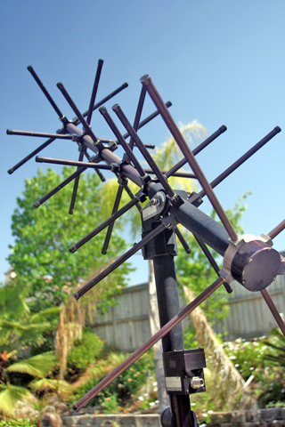
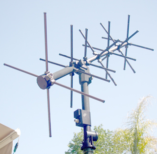
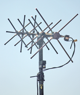
The antenna mast will have a central Type-N Jack and also a Micro-D connector with 9 sockets.
Photo of just the antenna at: http://www.solarix.net/shack/ Photos below courtesy of Brandon.
Gyroscopic Azimuth Sensor
This BEI QRS11 Gyrochip gyroscopic sensor in mounted inside the antenna positioner box (Fig 5)
The spec for long term drift is 0.2 Deg/sec so in 24 hours it might drift 17 degrees.
The under 100 second drift rate is 0.002 deg/sec so taking 5 seconds to make a right angle turn the drift would be 0.01 degrees.
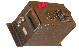
Antenna Positioner
Marking
Steering Assembly
p/n: 2095-137
for UHF Satcom Antenna System
p/n: AV 2095-2
s/n; xx System wt.: 28 lbs.
Trivec-Avanet Corp. FSCM 60188
Hunington Beach, CA 92647, USA
Front Panel Connectors
mil xxxx-10 10 male pins 3-lug, 3/4" O.D., 5 internal key slots
marked Bendix 21-204412-10P 9405 on inside
Has red & black wires and Black & white wires (4 total wires)
Pinout
Pin
wire
color
Function
A
red
Vehicle +24 supply
B
black
Vehicle ground
E
white
? Left/Right Up/Down ?
F
black
? ? ?
C, D
G, H
J, K
nc
not used
DC Power Cable
Made from:
PT06E12-10S
Power-Pole connectors in "24 Volt" configuration
Cooner Flex Wire with Silicon insulation
- RF:
Type-Nf jack.
- Circuit Breaker reset 5 Amps
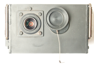
Fig 1 Outside 3/4 view
Cap installed on mast socket
Disk beside mast socket is locating pin
to keep mast from rotating.
Fig 2 Inside Left Plate
Fig 3 top with cap removed
showing the coax rotary joint and
micro D 9 pin connector
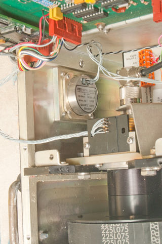
Fig 4 Step motor, control board, gyro,
American Precision Ind cmd-50 stepper motor ctrl
The black box mounted behind the front panel is a
Caledex DC/DC Converter 28D5.1000
18 - 54 VDC In
+/-5 VDC Out @ +1100/-900 ma
Fig 5 BEI QRS11 Gyrochip gyroscope
Stepper Motor & Controller
There are signs of corrosion at the bottom of the stepper motor (water got in the box?. . . or ?
3206623 ELECTRIC SYNCHRONOUS INDUCTOR MOTOR, Superior Electric Co., Sep 14, 1965, 310/162; 310/49.35; 310/156.64; 310/263
Patent numbers on the motor:
3734254 STEPPING MOTOR WITH AUTOMATIC BRAKE, Sigma Inst. Inc., May 22, 1973, 192/16; 192/223.1; 318/372
3777196 LOW-INERTIA SYNCHRONOUS INDUCTOR MOTOR, Sigma Inst. Inc., Dec 4 1973, 310/156.64; 310/49.32; 310/162
3956650 Laminar-rotor synchronous inductor motor, Sigma Inst. Inc., May 11, 1976, 310/156.65; 310/49.41; 310/162
4025810 Low noise synchronous motors, Sigma Inst. Inc., May 24, 1977, 310/162; 310/156.64
4255696 Synchronous motor system, Sigma Inst. Inc., Mar 10, 1981, 318/696; 310/49.43; 318/400.23 - fractional stepping
American Precision Ind cmd-50 stepper motor Controller box
with sticker: Sold by Servo Systems Co.
Connections are:
G/W: white
Gen: green
Red: red
R/W: Red/WhiteTo Stepper Motor
Run/Reset: nc
Half/Full: nc
Step In: white
CW/CCW: Green
ENA/nopwr: gray
5 VDC In: orange
ROI & ROI: resistor
Common Ground: black
+ Voltage Supply: Violet
To Controller PCB
Video
-------
-------
Interconnect Diagram
