Morris and Lee Gyroscope
Demonstration Apparatus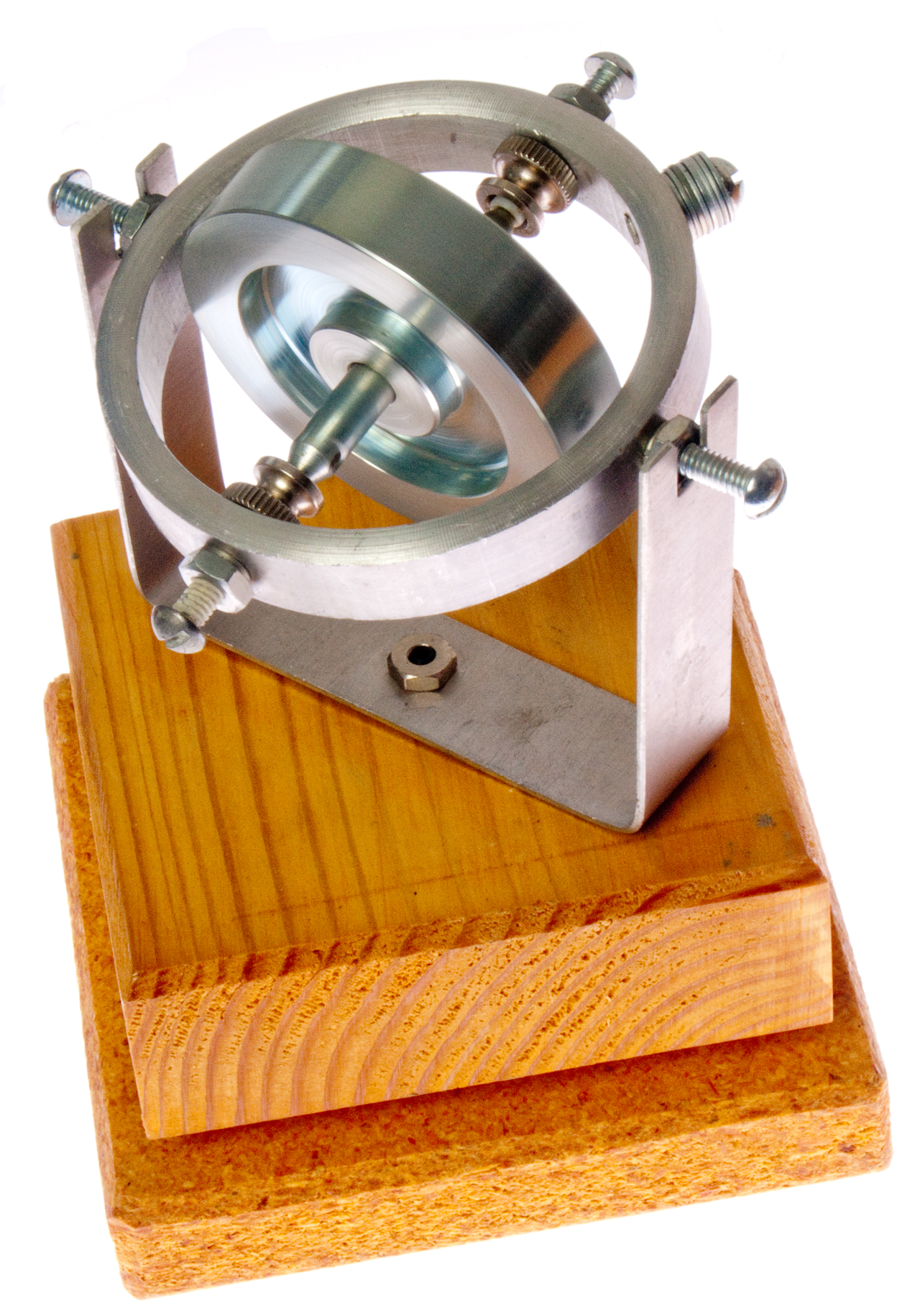 |
Super Precision Gyroscope (new web page) |
Demonstration
Gyroscope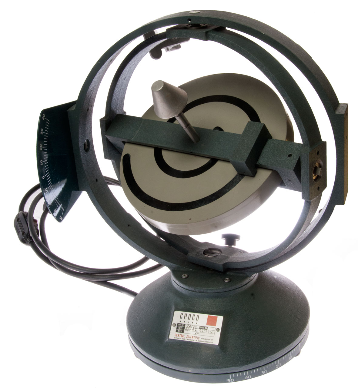 |
| Morris and Lee Gyroscope
Demonstration Apparatus |
Super Precision Gyroscope (new web page) |
Demonstration
Gyroscope |
Gyroscopes (Wiki) are one of many sensors used to measure our surroundings. There are many ways to measure gyroscopic forces the oldest being the rotating mass gyroscope.
Back in the 1970s I attended a talk by Charles and Ray Eames in Cupertino where the idea was that the design of a product where life and death is involved does not contain any marketing elements. It is a pure design. "With the limited restraints we can muster, we find it much easier to design an elegant flywheel for a gyro-stabilizer than an elegant hubcap for an automobile." Page 311, An Eames Anthology.
Also see my Flywheel web page.
Foucault
The book: Pendulum: (Wiki) Leon Foucault and the Triumph of Science by Aczel, Amir D says that Foucault was very interested in a physical proof that the Earth turns.
This had not been done, all observations were implied by astronomical methods and the mother church was not convinced. After building the Foucault Pendulum, many versions were built and installed in a half dozen locations to show people that the Earth was turning under their feet. Also to confirm his equation that the period was:
( 24 hours) / SIN(Latitude). i.e. at either pole the period would be 24 hours and at the equator the pendulum would not turn (infinite period).
This was not as clear cut a demonstration as he liked.
So he then came up with the gyroscope, but it only ran for maybe 10 minutes and you needed a microscope to see the effect of the Earth turning, so was not as good as the pendulum for public demonstrations. It was not until about 50 years later that the Orry device for steering torpedoes brought back the gyroscope.
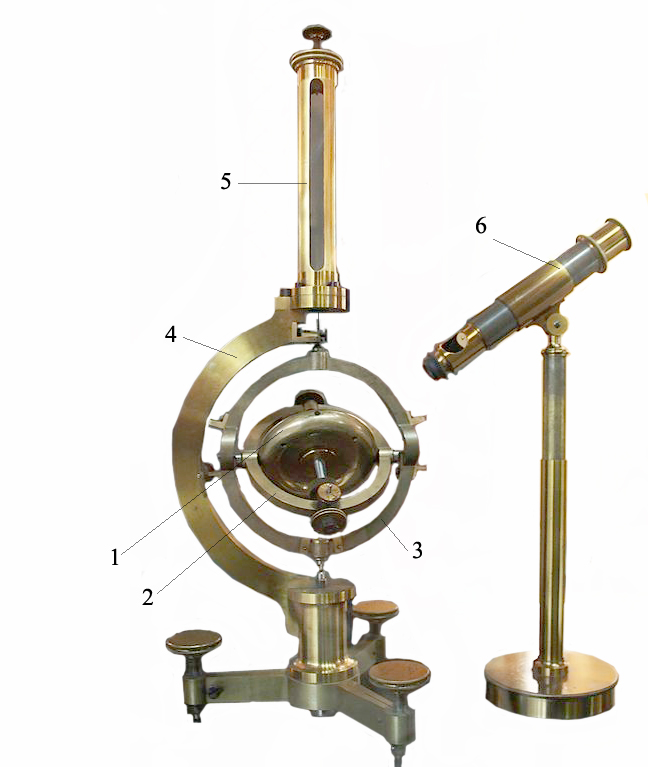
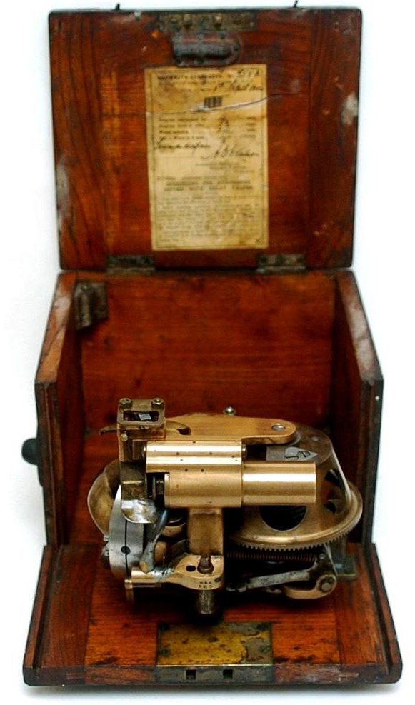
Replica of Gyroscope invented by Léon Foucault (Wiki) in 1852 used to demonstrate the rotation of the Earth. He came up with the name gyroscope (Greek for watching the rotation).
Note that Foucault's pendulum is really a form of gyroscope. Modern MEMS Vibrating Structure Gyroscopes (Wiki) work by vibrating back and forth, just like his pendulum.
1. Spinning Mass
2. gyro assembly
3. outer gimbal
4. frame
5 plumb
6. Microscope
Fig 0 - Foucault Gyroscope for Earth's Rotation
Photo from Wiki then background erased
The gyro assembly (2) is removable to allow spinning it up.
William Tobin - biographer of Foucault
The Life and Science of Léon Foucault: The Man who Proved the Earth Rotates
First with the Foucault Pendulum (Wiki) then the Gyroscope.
The microscope is pointing about half an inch too high. It should be pointing to the edge of the "L" shaped scale that's calibrated in 0.1 degree increments. Note there's another scale on the opposite side of the gyro assembly
The gyro assembly (2) can be removed to spin it up or to be placed on the simple wood stand for the third law demo. The assembly contains knife edges for mounting since there were no commercial bearings at this time.
Photo available from Science Museum, UK
I have erased the black background from the original photo to make it easier to see.
This photo shows the broom stick type pointer and it's associated scale.
The Microscope is out of position and should be as show above.
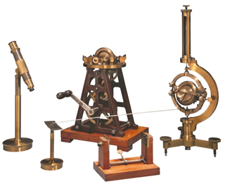
The winding stand is shown with a 2nd gyroscope assembly on top.
The stand in the foreground is to demonstrate that when a gyroscope is rotated it will align it's spin axis with the source, in this case when the stand is rotated the spin axis will move toward vertical. The lever on the stand (and the 2 levers on the stand to the right) are to help place the knife edges in the correct place then the lever(s) allow lowering the gyro assembly onto the flats.
PS the winding stand was also used to spin a copper disk in a magnetic field to demonstrate converting mechanical energy into heat.
also see Ref 20 Popular Science, July 1945 pg 86 to - 93 The Little Top That Aims a Gun - use as a sidereal clock, Mercury based compass
Instruments for Natural Philosophy - Electricity - Foucault's Disk - Note tower at right is the winding stand for his gyroscope.
Instruments for Natural Philosophy - Mechanics - Gyroscope -
Laws
Foucault had a gyroscope made to his specifications with the idea of using it to demonstrate that the Earth is revolving. He also showed that he could find true north using only his device. He named the device gyroscope because this device was about watching the earth turn. Prior "tops" were a scientific curiosity and how they worked was a source of speculation. He may have thought what would happen if he could make a pendulum spin in a full circle (become a flywheel) then a flywheel could be used to demonstrate the earth turns. But the flywheel could be much smaller than the pendulum which required a support on the order of 30 feet long, i.e. a very large auditorium was required.
I have rephrased the laws so they are parallel to Newtons Laws (Wiki).
Newton
Foucault First
When viewed in an inertial reference frame, an object either remains at rest or continues to move at a constant velocity, unless acted upon by a force. When viewed in an inertial reference frame, a the spin axis of a free gyroscope1 points in a constant direction.
Second
The vector sum of the forces F on an object is equal to the mass m of that object multiplied by the acceleration vector a of the object: The moment of momentum of a body about an axis is defined as its moment of inertia into the angular velocity about the axis, and this is evidently the time integral of the couple acting about the axis.
C * omega * theta dot = A * phi double dot 2
Third
YouTube
When one body exerts a force on a second body, the second body simultaneously exerts a force equal in magnitude and opposite in direction on the first body. A gyroscope will try to align it's spin axis with the spin axis of the reference frame it's in.
The axis of precession will be perpendicular to both the spin axis and torque axis.1. a free gyroscope is in gimbals that allow movement in any direction without any constraints.
2. Where:C is the moment of inertia at right angles to the flywheel spin axis
omega is the speed of the flywheel in radians per second
theta dot is how fast the angle theta changes (its velocity), where theta is the angle relative to the spin axis in radians
A is the moment of inertia about the flywheel spin axis
phi double dot is the angular acceleration of angle phi, where phi is an angle at right angles to both the spin axis and theta in radians
Papers
In the french language book Recueil des Travaux Scientifiques, Volumes 1 - 2 by Charles Marie Gariel, Leon Foucault & J. Lissajous 1878 there are some original papers by Leon Foucault relating to the Gyroscope and many papers on other topics.
Chaleur Produite par L'influence de L'aimant, Sur les corps enn Mouvement, Academe de Scoemces, 12 Sep 1855.
This is a paper about converting mechanical energy into heat by rotating a copper disk at high speed using a hand crank tower of gears. This tower similar if not identical to the hand crank tower of gears used to spin up the gyroscope wheel prior to placing the wheel into one of the two stands. Includes an illustration of hand crank tower gear stand.
The Mecanique section starts with a number of papers on the pendulum the first one dated 26 July 1847.
Influence du Mouvement de la Terre sur la Toupie, son Inclinaison dans le Plan du Meriden, et sa Progression D'occident en Orient sur un Plan Horizontal (without date)
Sur Quelques Experiences, Tendant a Demontrer, La Tendance des Rotations au Parallelisme, academic de Sciences 26 Oct. 1852
Instruction, Sur les Experiences du Gyroscope (without date).
I think this is the first use of the word Gyroscope and contains a somewhat detailed description of the major components and three demonstrations (Laws).
The next papers are about the Heliostat (plate 13), Siderostat (plates 14 & 15) and many related to the Foucault knife edge optical test (Wiki) + information on carbon arc mechanisms.
Note the first ball bearing of a quality suitable for use on a gyroscope was patented by Jules Suriray (Wiki) in 1869, long after Foucault made his demonstration, hence no ball bearings were used, only knife edge suspension (Precision Clocks Q3 web page) and pointed shafts for low friction. These suspensions have a very limited amount of tilt.
Electric Motor
In 1890 George M. Hopkins (Ref 16) built the first gyroscope with an electric motor.
This is a very simple DC motor.
The 1908 Electromagnetic Toy Engine has very similar construction.
The flywheel was made out of a non ferrous metal and a flat iron strap was attached across a diameter so that the two early telegraph type coils had something to attract that was different at different angles of rotation, i.e. a solid iron flywheel would not have worked.
This is a precession demonstration gyroscope.
YouTube: Gyroscope precession and nutation by toc1955
It has the look and feel of this one, maybe inspired by Hopkins book?
Electrical connections made by support metal pedestal and wire sticking into a Mercury moat. Allowing continuous precession. toc1955 used a slip ring.
The coil spring keeps pressure on the brush touching the rotating commutator.
This gyroscope is not in balanced gimbals and so will not demonstrate the Earth's rotation.
This may be a Plücker and Fessel gyroscope sold by Scientific Apparatus Company (see Gyroscopes)
PS I've erased the background because plate I in Ref 16 was an engraved plate with horizontal lines covering 100% of the plate adding a lot of confusion.
3137093 Electric gyroscope toys, Ulrich Aaron, 1964-06-16, - adds motor & 4 ea AAA batteries to conventional toy gyroscope toy.
Biological
While learning about Blind Flying I discovered that Doolittle said that humans were not designed to fly. That's to say we do not have the needed senses. This implies that flying animals must have what amounts to a gyroscope. A YouTube search for "Bird Gyroscope" returns a number of examples of birds that seem to have a gyroscope inside their heads.
More about this at Skylight Compass\Biological Examples.
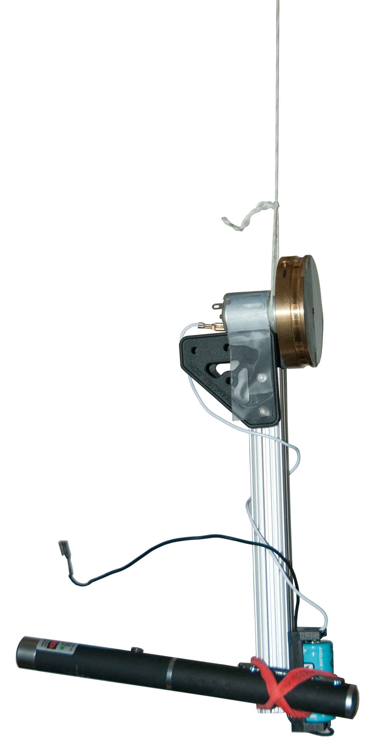
This idea is to be able to demonstrate both the rotation of the Earth and North Finding.
The key components are a brass flywheel that's about 2" in diameter and 1/2" thick mounted to a small DC permanent magnet motor and powered by a battery.
The Foucault gyroscope was spun up using a hand crank and gearing and then it slowed down as time went on. It was said to be useful for about 10 minutes.
The speed is given as 150 to 200 Revolutions per second ( 9,000 to 12,000 RPM). His flywheel is no more than twice as large as this on and this setup gives a speed just under 17,000 RPM. So the Foucault gyro has more rotational momentum but I doubt by more than a factor of 4. This may or may not be critical is getting this one to work. The laser pointer was added when I was optimistic, but now serves only as an adjustable weight.
The first try did not work, the gyroscope was rotating in azimuth
YouTube - First Test of Free Gyroscope suspended by a string.
For the second test I rearranged the configuration to make a "pendulous gyroscope" and waited for the rotation (string stretching) to stop.
Then when the gyroscope is powered the whole assembly rotates counterclockwise with a period of about 4 minutes.
In any system involving a gyro it's important to understand how drift is compensated. For example in early Inertial Navigation Systems (INS) used in submarines they would need to reset the system using a sextant or the TRANSIT navigation system because the INS has long term drift.
The nature of a gyroscope is to translate any force using the right hand rule where the three principal axis are:
1. the center line of the rotating mass
2. an axis at right angles to (1)
3. an axis at right angles to (1) and (2)
Any force in line with (2) gets translated into a force on axis (3) and vice versa.
The problem comes about because any friction in the bearings will cause axis (1) to move. This is expressed in the long term drift rate.
In the March/April issue of Inside GNSS, "The Promise of MEMS" by Naser El-Sheimy & Xiaoui Niu, Fig 1 "Bias Stability vs. Nominal Size of Mature Gyro Technology" from a paper by Dr. Robert J Smith of Honeywell (using Ring Laser, electrostatic, hemispherical resonator, fiber optic, 2 degrees of freedom rotor, quartz plate.) Y-axis is the log physical size in mm the X-axis is log Long term bias stability deg/hr). The interesting thing is that the data falls on a straight line. At 0.001 deg/hr the line is at 100 mm and at 10 deg/hr (4 decades away) the size is 10 mm (one decade). So as the sensor gets smaller the LTDR goes up as 10 ^ 4.
But if a MEMs sensor has predictable long term drift over some short time period then it can be backed out. In that case the short term noise (100 second bias instability) becomes important. In the above article there's an example system using MEMS gyros and accelerometers. They are using forward filtering and backward smoothing to get a reasonable result for short GPS outages.
Technology
Drift deg/hr
RLG
Ring Laser
7E-4 - .5
ESG
Electrostatic
1E-3
HRG
Hemispherical Resonator
3E-2
FOG
Fiber Optic
.3
2DF
Two Degrees of Freedom rotor
10
QRS
Quartz Rate Sensor
7 - 1000
MEMS
Micro Electrical Mechanical System
>1000
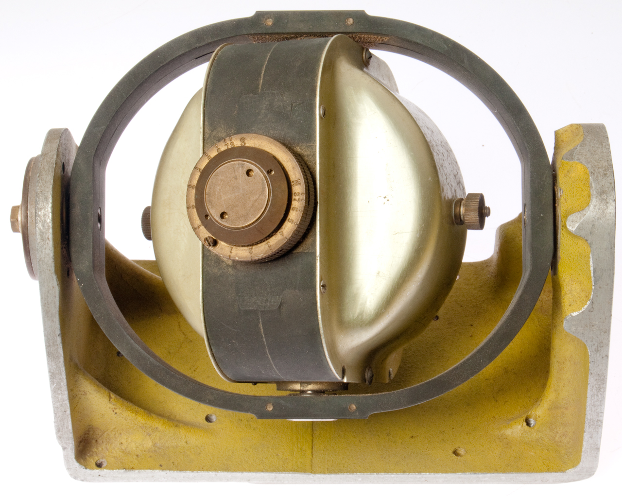
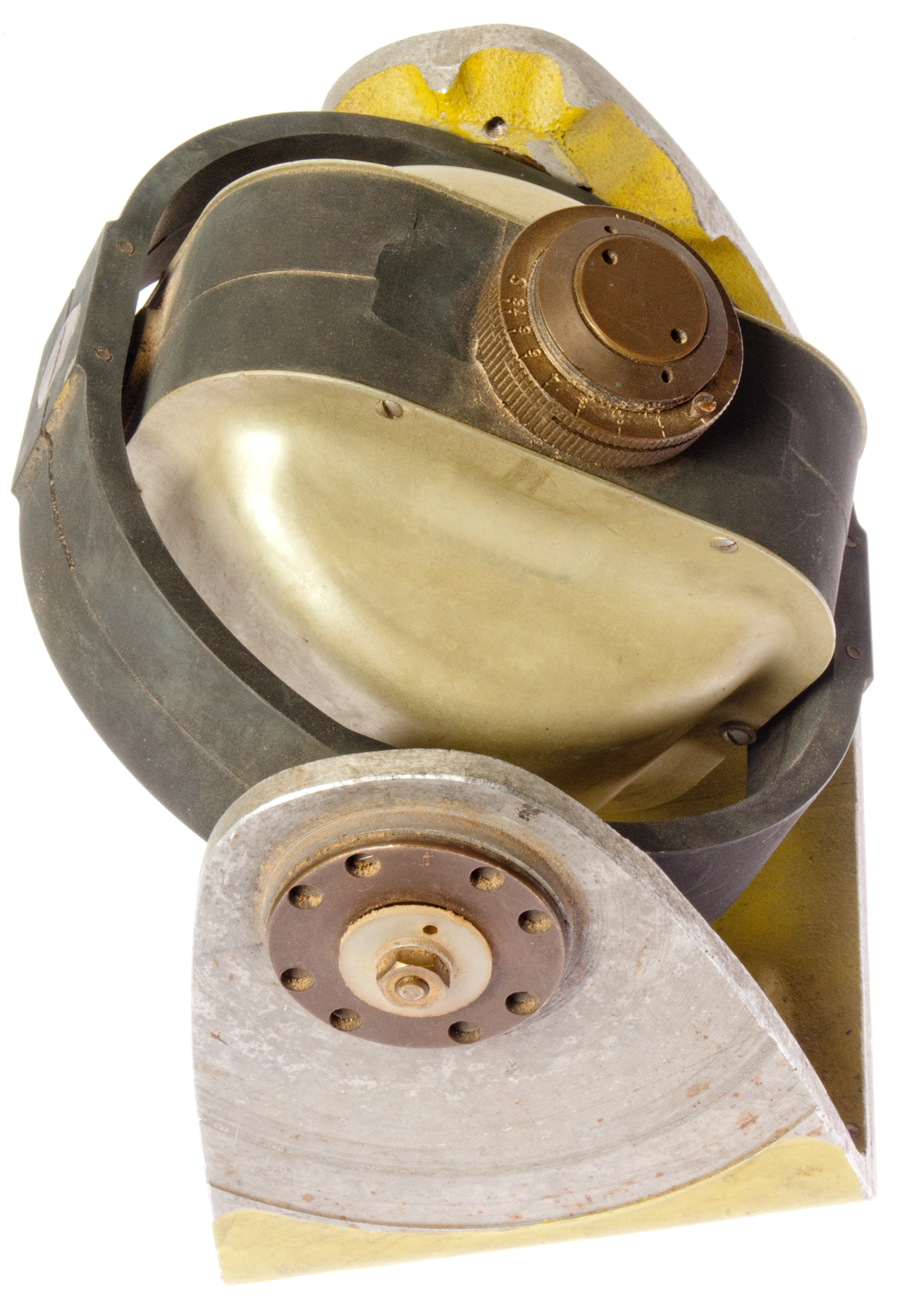
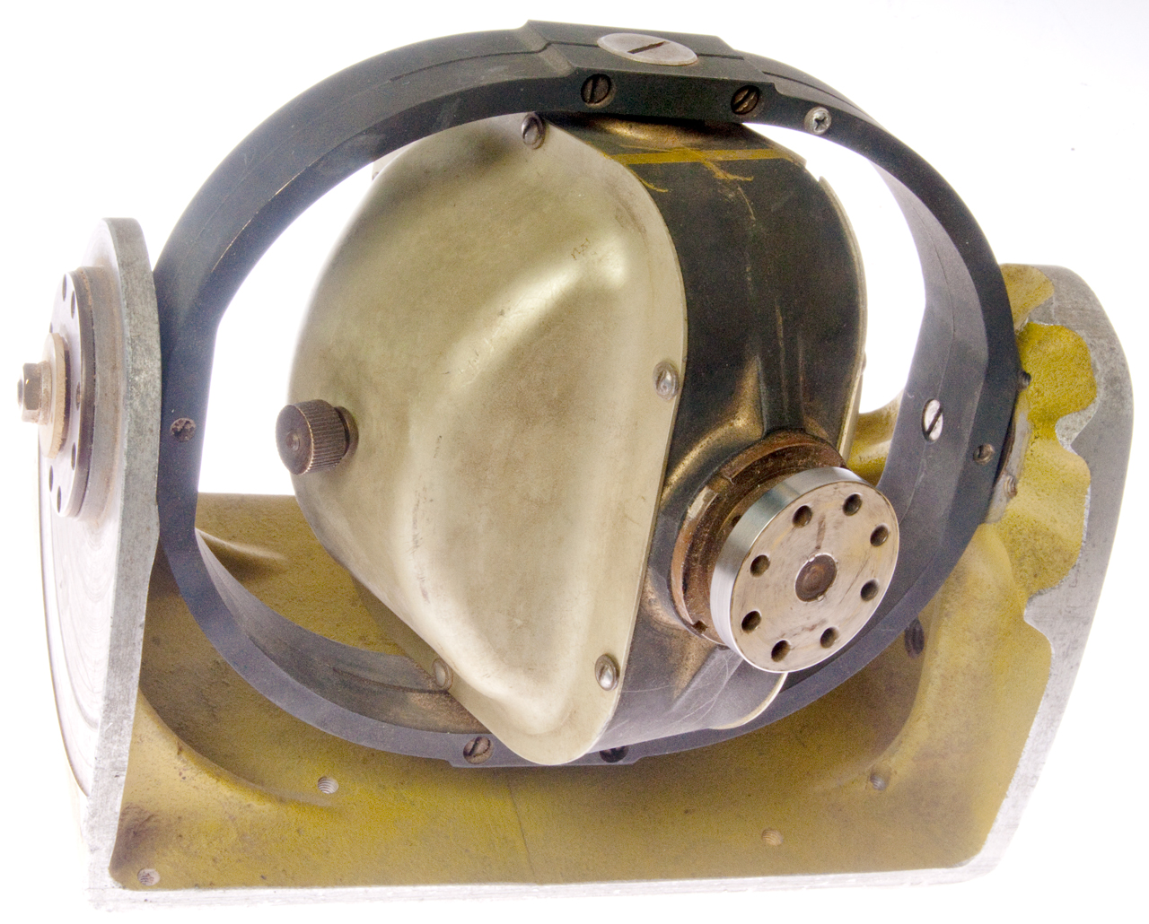
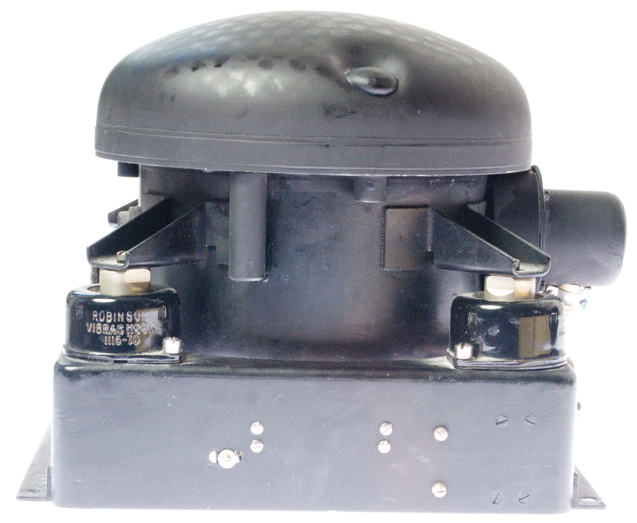
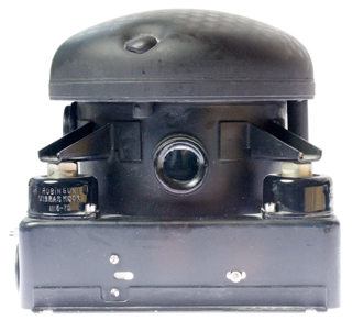
This unit is mounted in a gimbal so that when the base is moved the gyro axis remains fixed.
Fig 1 Front View
The thumb nuts to the right and left are probably for
adding weights or springs.
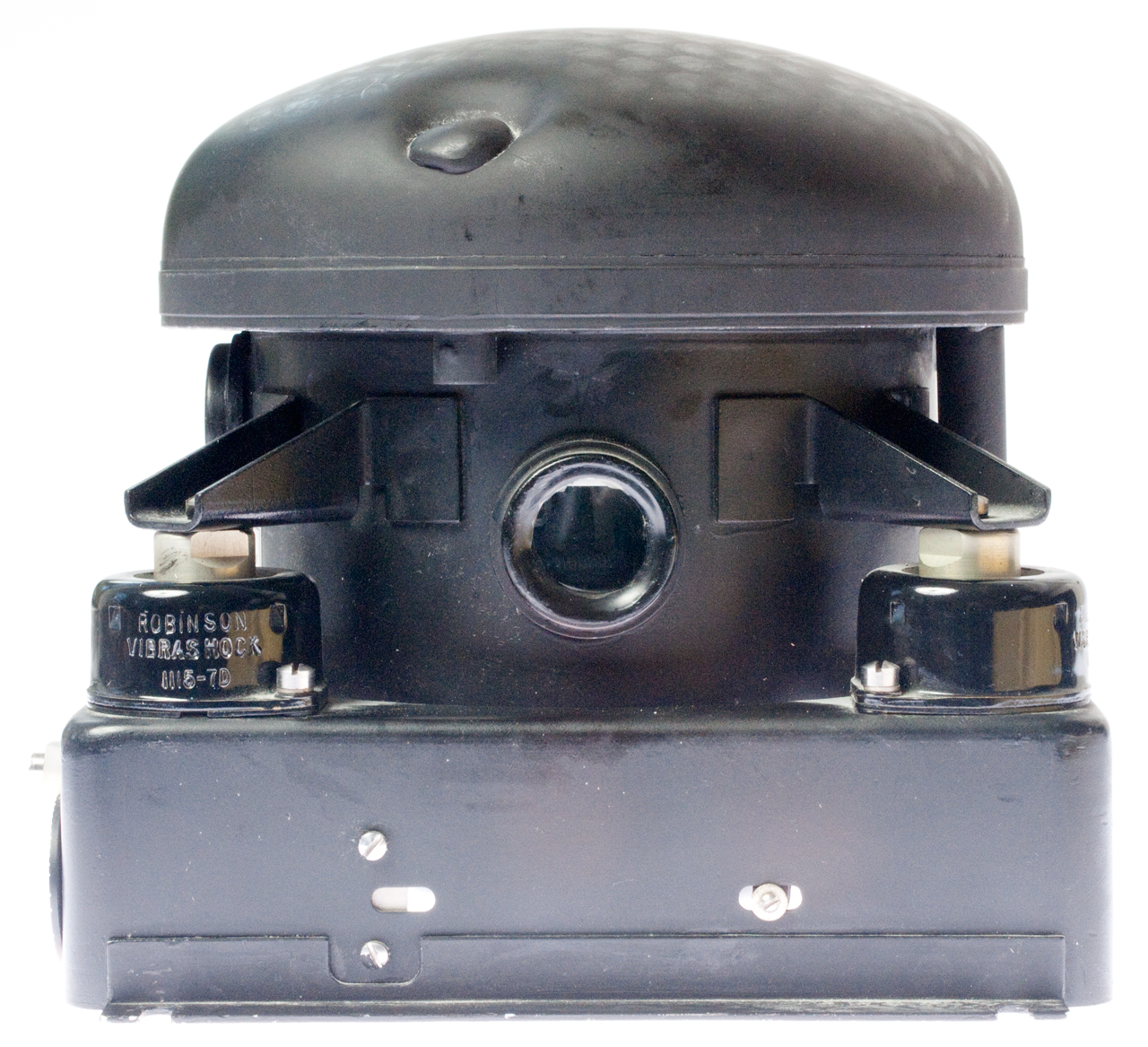
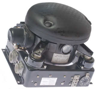
Fig 2 Adjustment on flywheel axis does what?
Adjustment on gimbal axis does what?
Let me know
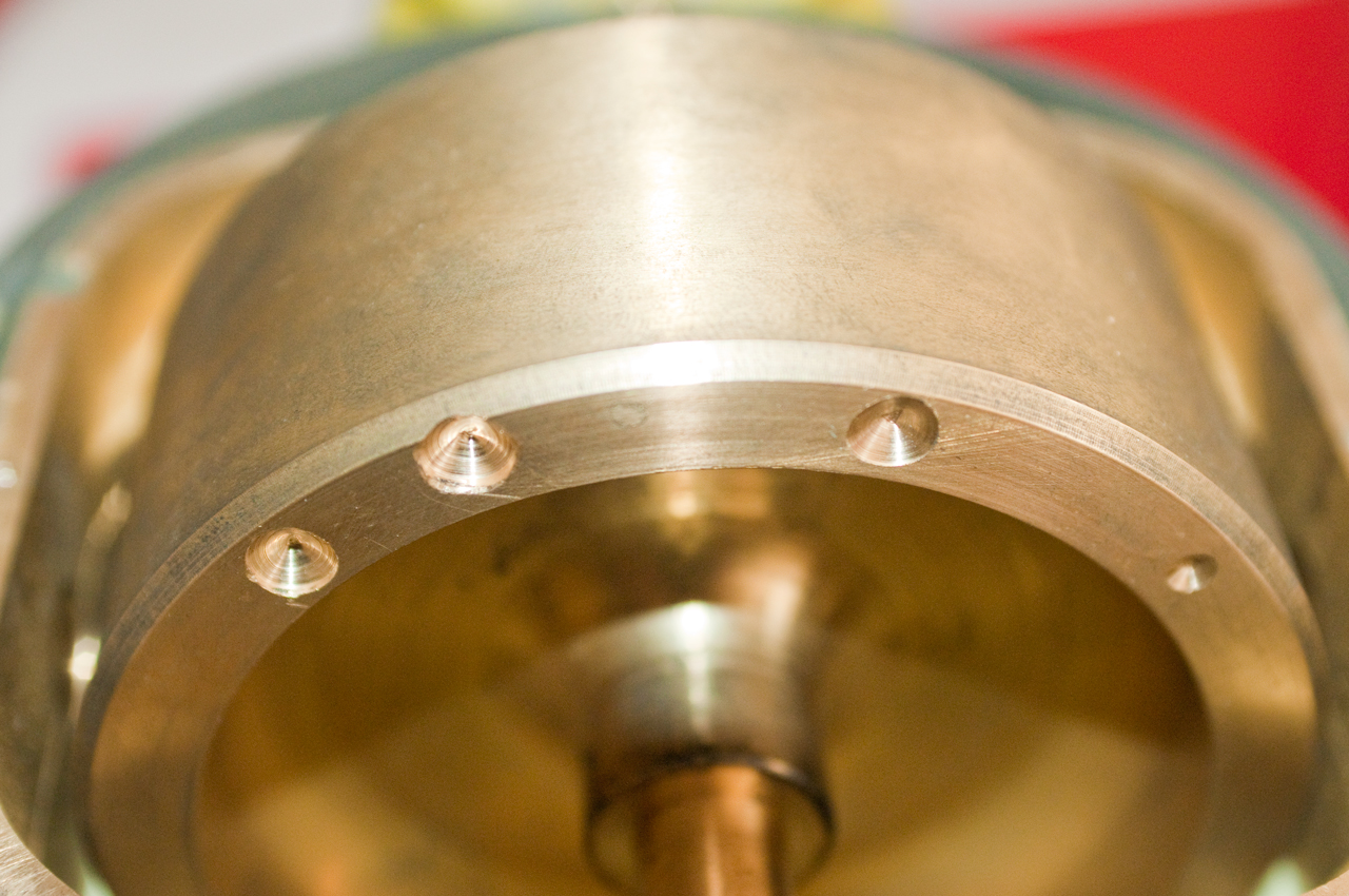
Fig 3 Drive flange
Flywheel with balancing drill holes
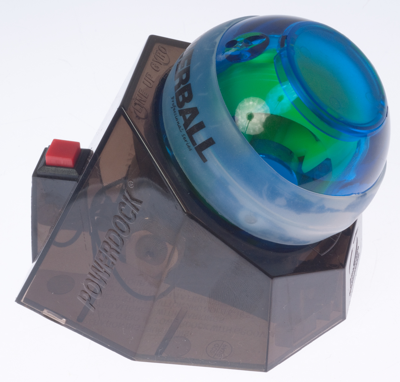
These are sold as exercise devices for you wrist muscles. They depend on gyroscopic forces.
Once the wheel is spinning then by making a circular motion you can increase the speed of the wheel and keep it spinning. As the wheel goes faster and faster (RPM indicator on order) it takes more and more force to make the motion, thus increasing you strength.
PowerBall on PowerDock
Speedometer
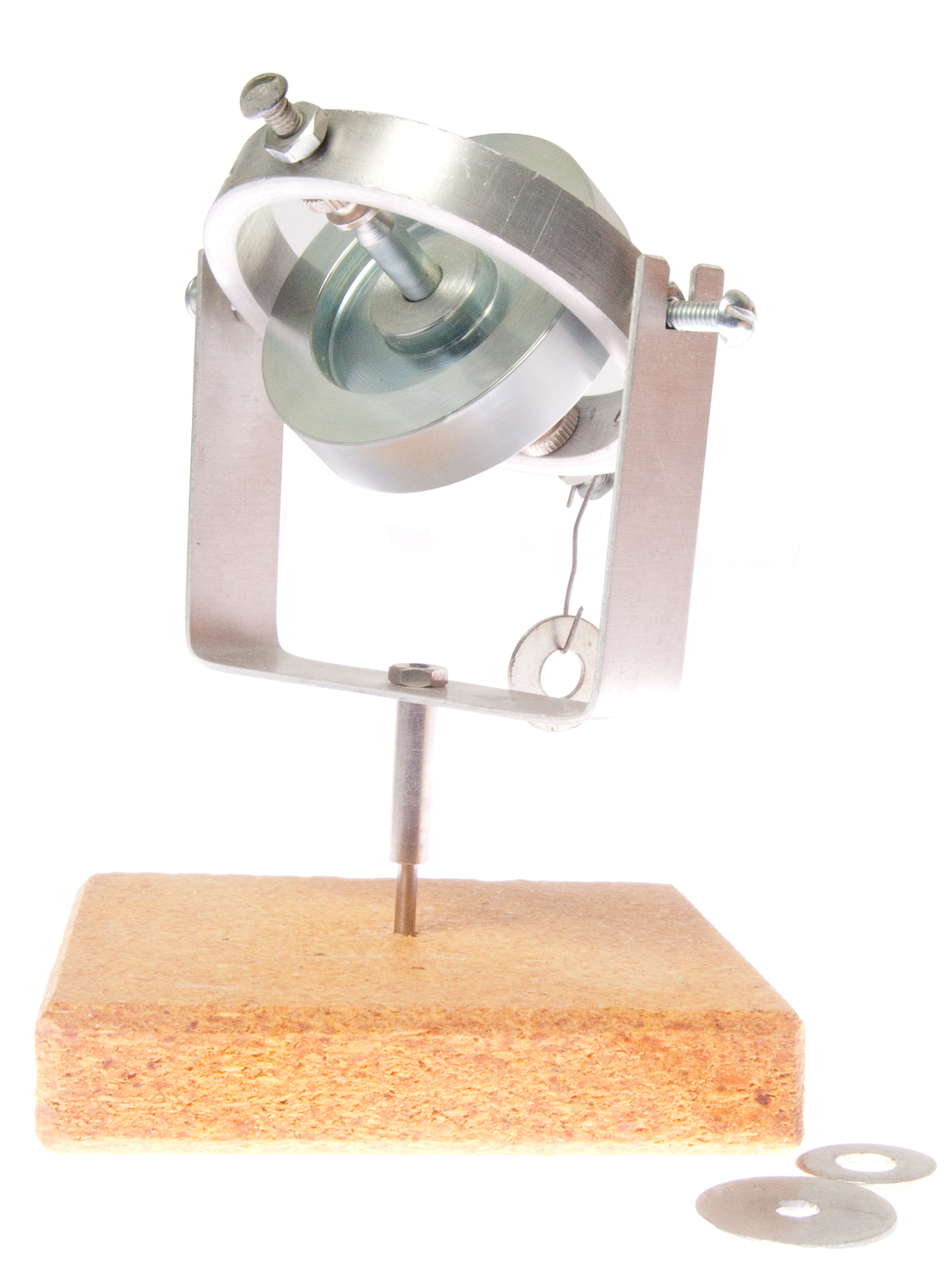
This is the GY-2 (with a 2-1/4" dia. spinning mass).
Comes with paper clip and washers to do experiments.
Fig 4
Fig 5
Fig 6
Part of the Trivec-Avant AV 2095 UHF Satcom Antenna System that keeps the antenna pointed in the same azimuth as the vehicle turns.
October 2018 on eBay Buy It Now for $8,500.
One of the photographs shows a patent label with the following Sperry patent numbers:
Marked:
Sperry Gyro-Compass
Manufactured by
Dodge Division
of Chrysler Corp.
MASTER COMPASS
Mark-XIV Mod-1
used on a ship.
1499322 Compensated gyroscopic compass, Filed 1919-02-17, Pub 1924-06-24
1507653 Compass relay transmitter
1527932 Alarm device for gyrocompasses
1626123 Gyrocompass relay transmitter
1679438 Stabilized gyroscopic compass
1686524 Gyroscopic compass
1694192 Gyroscopic compass
1709395 Gyroscopic compass
1724432 Repeater compass
1728185 Direct-current gyrocompass - a bad idea since carbon dust from brushes causes problems
1773411 Gyroscopic compass
1780014 Constant-period compass
1782048 Gyrocompass reversing contact
1866733 Gyroscopic compass
1887318 Follow-up system for gyrocompasses
1917017 Gyrocompass transmission system
2095313 Air borne gyrocompass, Filed: 1935-10-03, Pub: 1937-10-12
2098580 Angular motion indicator
2110766 Gyrocompass - ship
2128559 Gyroscopic compass - ship
2157360 Correction device for gyrocompasses - TAN(E) = [S * COS(C)] / [V * COS(L)] E: error, C: Course angle, S: Speed, V: Earth's Equator speed, L: Latitude
2158048 Constant period gyrocompass
2213832 Antivibration mount for direction indicating instruments, Filed: 1937-04-07, Pub: 1940-09-03
YouTube:Design of the Sperry Mk XIV Gyro-Compass - this is why the high price.
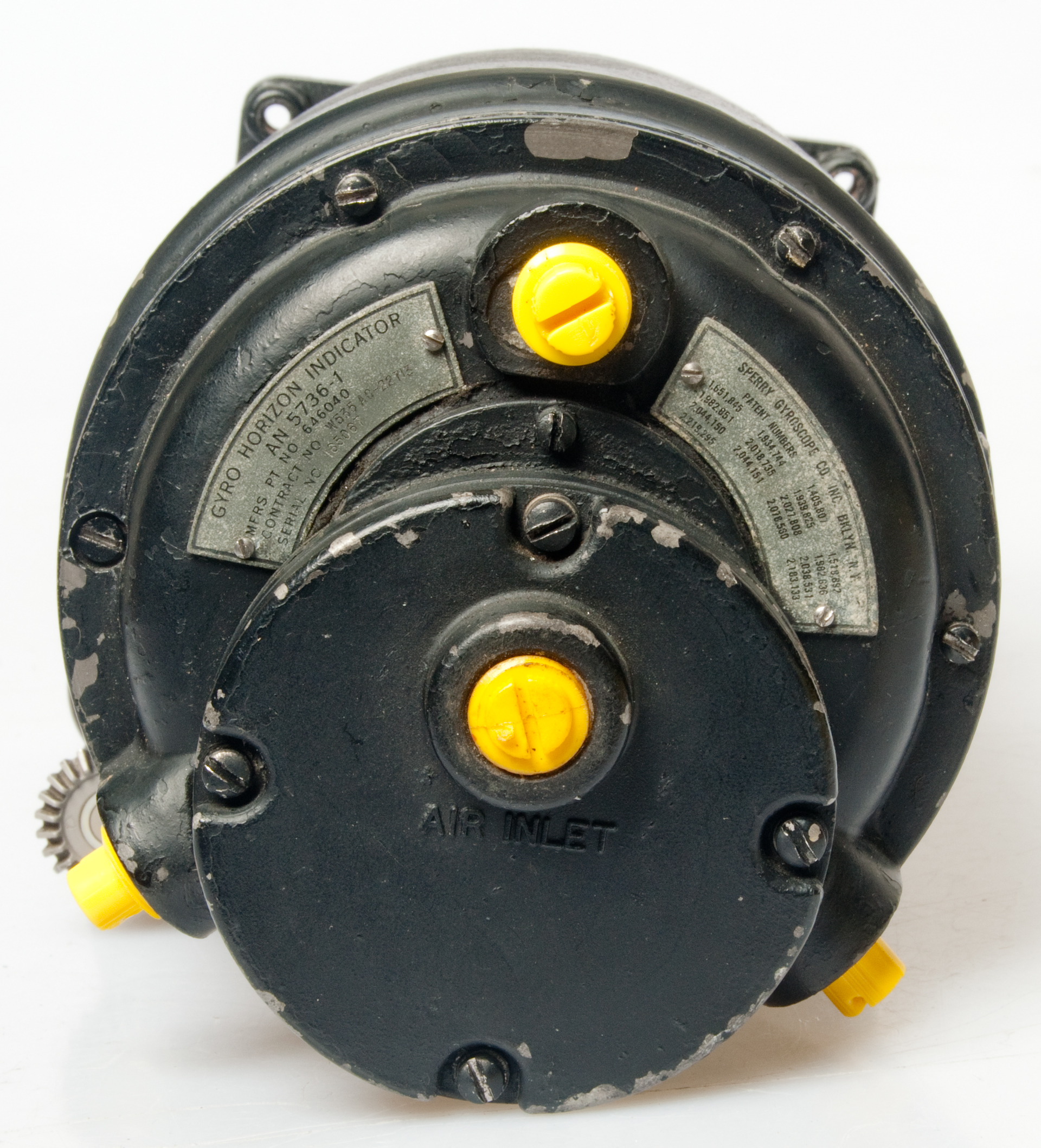
Powered by Pitot tube (Wiki) vacuum.
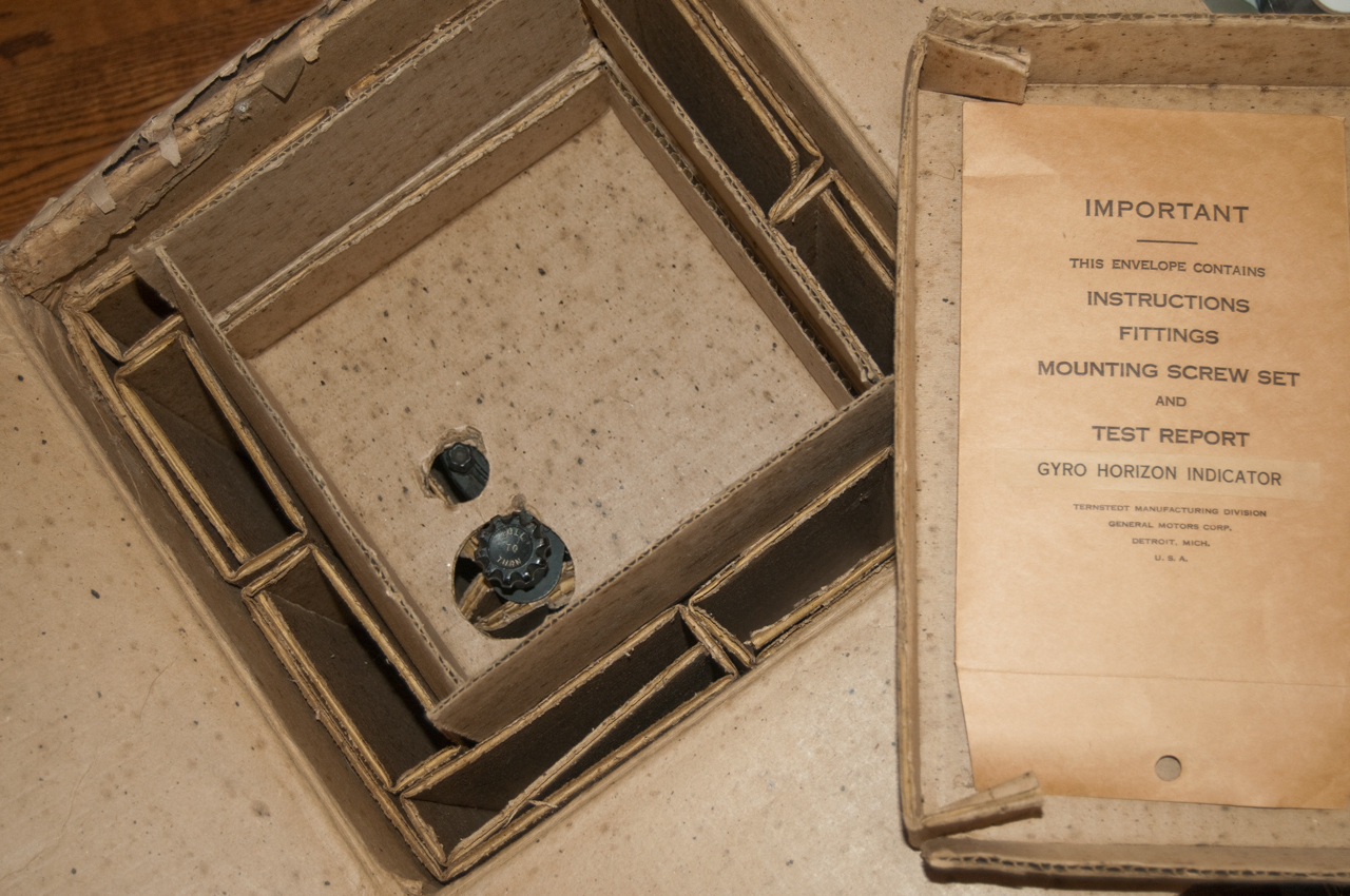
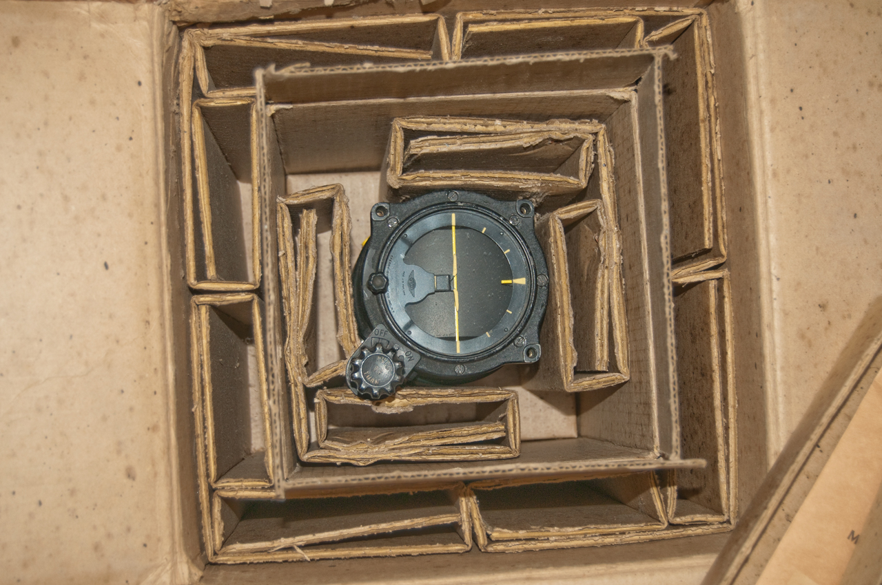
New In Box factory packaging
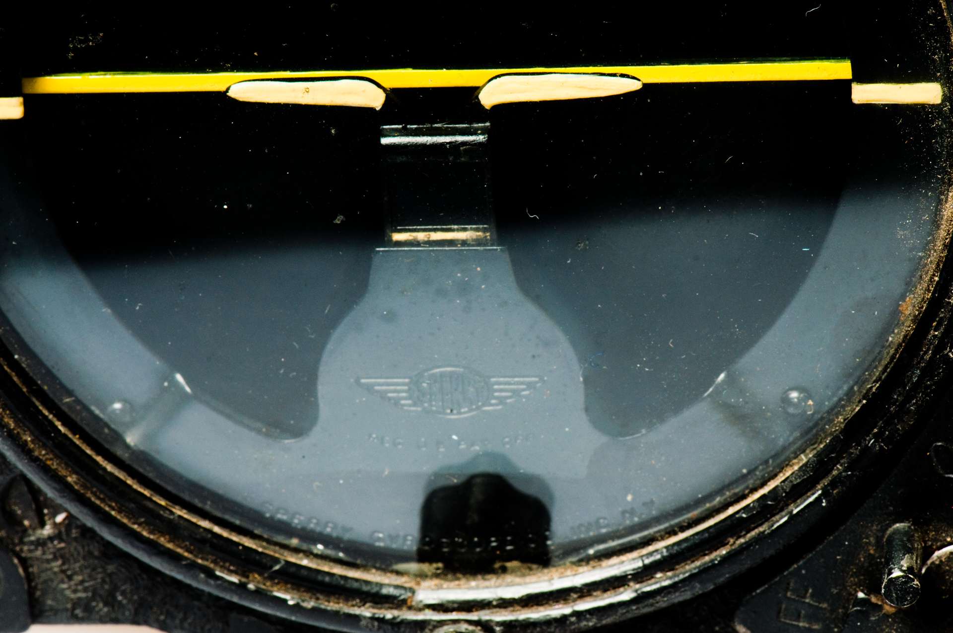
Sperry trademark lower front center
These are also called heading indicators (Wiki).
This is a standard one unit panel size aircraft instrument that displays the horizon. It's marked with the following patent numbers:
1405807 Damping Means for Gyroscopes, H.L. Tanner (Sperry Gyroscope Co), Feb 7, 1922, 74/5.44; 33/345
1518892 Self-Damping Gyropendulum, M.F. Bates (Sperry Gyroscope Co), Dec 9, 1924, 74/5.43
1651845 Gyroscopic Pendulum, E.A. Sperry (Sperry Gyroscope Co), Dec 6, 1927, 74/5.43; 33/328; 74/5.7 - damping
1934744?
1939825 Gyroscopic Horizon Indicator, F.C. Narvensen (Sperry Gyroscope Co), Dec 19, 1933, 33/328; 74/5.43
mentions 1982851 not good for aerobatics
1982636 Air Driven Vertical Gyro, B.G. Carlson (Sperry Gyroscope Co), Dec 4, 1934, 74/5.43; 33/329; 74/5.7 - good for loop-the-loop
1982851 Flight Indicator, P.R. Bassett (Sperry Gyroscope Co), Dec 4, 1934, 33/329; 33/318; 33/352 - not good for loop-the-loop.
2018735 Gyrovertical, F.C. Narvensen (Sperry Gyroscope Co), Oct 29, 1935, 74/5.1; 33/318; 33/329; 74/5.7 - caging at will
2027808 Artificial Horizon for Aircraft, B.G. Carlson (Sperry Gyroscope Co), 73/495; 33/329; 33/351; 73/179; 74/5.8; D10/67 -
shows gain or loss of altitude even if no pitch change (air pocket)
2038531 Attitude Indicator for Aircraft, P.R. Bassett (Sperry Gyroscope Co), Apr 28, 1936, 33/328; 33/333; 33/350; 33/351; 248/27.1
ball in curved glass tube + gyro indicator
2044150 Artificial Horizon, B.G. Carlson (Sperry Gyroscope Co), Jun 16, 1936, 33/329; 33/351 - added angle of tilt scale
2044151 Artificial Horizon, E.A. Sperry (Sperry Gyroscope Co), Jun 16, 1936, 33/329; 74/5.43; 244/1.00R
part of using patent 1992970 on an instrument panel
2078560 Artificial Horizon B.G. Carlson (Sperry Gyroscope Co), Apr 27, 1937, 33/329; 33/333; 116/DIG.43 - OK for stung flying
2183133 Artificial Horizon, L.F. Carter (Sperry Gyroscope Co), Dec 12, 1939, 33/329; 74/5.60R - magnified tilt angle display
(on 5736-1) 2219295 Pneumatic erection device for gyroscopes, Leslie F Carter, SPERRY GYROSCOPE CO Inc,
-----------------------------
The following Sperry patents are for the gyro Compass panel instrument.
1451928 Magnetic Gyroscopic Navigation Device, Harry L. Tanner (Sperry Gyroscope Co), Apr 17 1923, 33/318; 33/319; 33/356; 74/5.1 - uses both mag compass & gyro for deviation Uses a cone to cage the gyro.
1757096 Gyroscopic Pilot for Airplane, Lawrence B. Sperry (Sperry Gyroscope Co), May 6, 1930, 114/144.00R; 74/5.00R; 114/144.00E; 244/175 -
1788807 Control Gyro, Elmer A. Sperry (Sperry Gyroscope Co), Jan 13, 1931, 74/5.1; 33/328 - automatic restoration to horizontal
1851536 Directional Gyroscope, M.F. Bates (Sperry Gyroscope Co), Mar 29, 1932, 33/318; 33/351; 74/5.00R; 74/5.1 - dirigible short term course devation (air jets power rotor)
----- all the above instruments can only display a course change of less than about 45 degrees ----
1974220 Direction Indicator, Elmer A. Sperry (Sperry Gyroscope Co), Sep 18, 1934, 74/5.14; 33/318; 33/326 - "Directorscope" capable of 180 turns (i.e. full circle display) Venturi vacuum powered
1982635 Air Driven Gyroscope, B.G. Carlson (Sperry Gyroscope Co), Dec 4, 1934, 74/5.43; 74/5.7 -
1982636 Air Driven Artificial Horizon, B.G. Carlson (Sperry Gyroscope Co), Dec 4, 1934, 74/5.43; 33/329; 74/5.7 - closley related but not a directional gyro
1982637 Directional Gyroscope, G.G. Carlson, (Sperry Gyroscope Co), Dec 4, 1934, 74/5.7; 74/5.1; 74/5.43 -
While the magnetic and earth inductor compasses are fairly satisfactory for straight courses, they become practically useless during turning or rapid acceleration of an airship and during maneuvers. A free gyroscope on the other hand will maintain it's direction regardless of such maneuvers but the application of a free gyroscope to airplanes has heretofore been limited on account of the fact that the gyroscope would not maintain it's direction for more than a few minutes. One of the principal causes of deviation has been that such gyroscopes have a tendency to become inclined to the horizontal due to the rotation of the earth and other causes so that in a comparative short time they lose their directive value. Also free gyroscopes stray in azimuth in most latitudes for like reasons.1988521 Gyro earth inductor compass, Jr Elmer A Sperry, Bruno A Wittkuhns, Sperry Gyroscope Co Inc, 33/317.00R, 324/246, 33/316, 324/345, 33/362, 33/321 -
End walls beside the buckets that are part of the air drive cause the rotor to right itself.
2015650 Directional Gyroscope, M.F. Bates (Sperry Gyroscope Co), Oct 1, 1935, 33/318; 33/327; 74/5.4; 74/5.43 -
(patent 1982637) does not function properly if the airplane permanently assumes a list or tilt, because the air erecting couple is referred to the position of the airplane rather than to the gravitational vertical. . . my invention eliminates the disturbing effect by using gravity as a baseline...2025194 Directional Gyroscope, L.F. Carter et al (Sperry Gyroscope Co), Dec 24, 1935, 74/5.7; 33/318 - fixes bearing problem with cold temperature
2047186 Temperature Compensated Gyroscope, M.F. Bates (Sperry Gyroscope Co), Jul 14, 1936,
2047984 Electron Tube Control for Reversible Motive Means, A.S. Riggs (Sperry Gyroscope Co), Jul 21, 1936, 384/538; 74/5.00R; 74/5.7; 415/135 -
allows use at high altitudes without slowing or stopping rotor2052866 Pilot Directing Gyroscope, B.G. Carlson (Sperry Gyroscope Co), Sep 1, 1936, 33/230; 33/318; 89/202 - includes improved caging & rotor speed indication
problem caused by dissimilar metals: brass rotor, aluminum frame, steel shaft
318/297; 236/69; 307/32; 307/38; 318/252; 318/675; 318/677
2061894 Constrained Directional Gyroscope, B.G. Carlson (Sperry Gyroscope Co), Nov 24, 1936, 33/318; 74/5.14; 188/158; 188/164; 235/144.00E - permanent magnet applies a correcting torque
2086896 Air supported gyroscope, Leslle F Carter, Sperry Gyroscope Co Inc, Jul 13, 1937, 74/5.43, 33/327, 384/99, 74/5.7, 33/318 -
2092032
2093417
2093417 Directional Gyroscope for Aircraft, L.F. Carter (Sperry Gyroscope Co), Sep 21, 1937, 33/318; 33/327; 74/5.43 -
display looks like a compass card face rather than the more common edge making it much easier to read.2111388 Ganging means for Directional Gyroscopes, B.G. Carlson (Sperry Gyroscope Co), Mar 15, 1938, 33/318; 33/351; 74/5.14 - knob pulled out for setting.
unlike in 1974220 which was pulled out for normal operation causing injury in case of a crash.2135229 Gyro Magnetic Compass, M.F. Bates (Sperry Gyroscope Co), Nov 1, 1938, 33/316; 33/327; 74/5.7
RE209832174777 Directional Gyroscope
2180136 Temperature Compensated Gyroscope, M.F. Bates (Sperry Gyroscope Co), Nov 14, 1939, 384/540; 74/5.00R - fewer parts than 2047186
2217616 Gyro-Magnetic Compass,
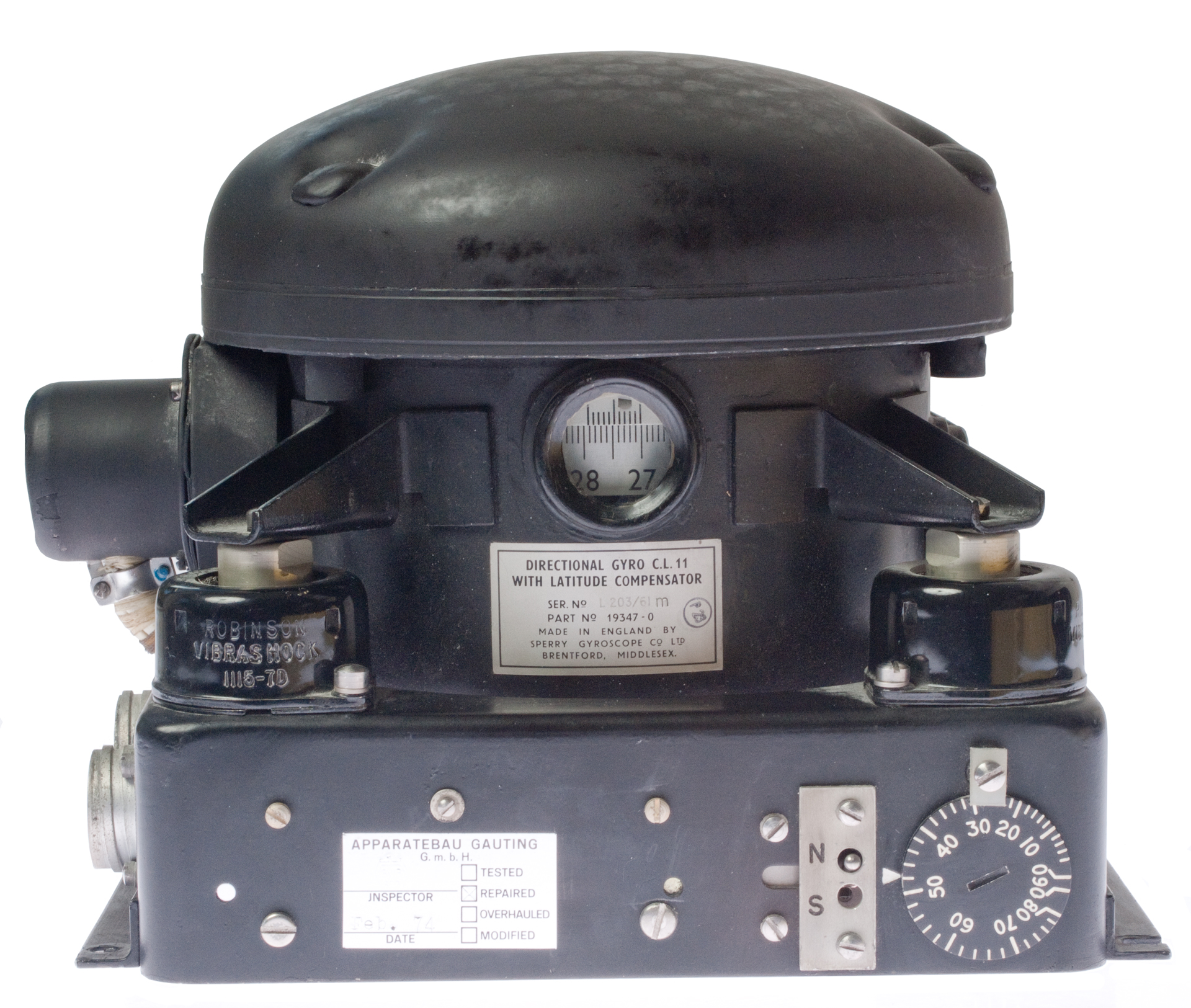
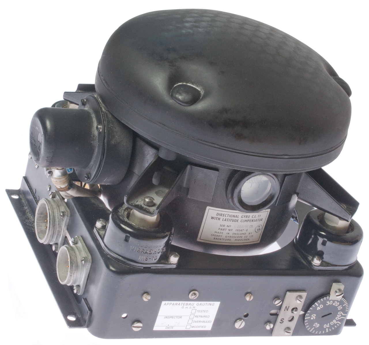
Directional Gyroscope C.L. 11 with Latitude Compensator
Ser. No. L203/61 m
Part No. 19347-0
Made in England by
Sperry Gyroscope Co Ltd
Brentford, Middlesex
I've heard that this might have been part of the co-pilot's gyro compass system in the KC-135 mid 1970s vintage.
If you have any information about this unit please let me know.
This looks pretty much like the Sperry p/n 2588302 Directional Gyroscope.
Repaired Feb 1974


When located in a dynamic platform, like an airplane, the gyro needs to be located at the center of mass of the vehicle. This way when the plane banks, pitches or yaws the gyro will only respond to the angles. But if it's located anywhere else it will be in error. This applies to models as well as to full size vehicles. When Harrison first tested his chronometer at sea the movement of the ship caused errors in time. If he had located the clock at the center of mass of the ship I think it would have worked much better.
The instrument panel mounted directional gyros suffer from this problem.
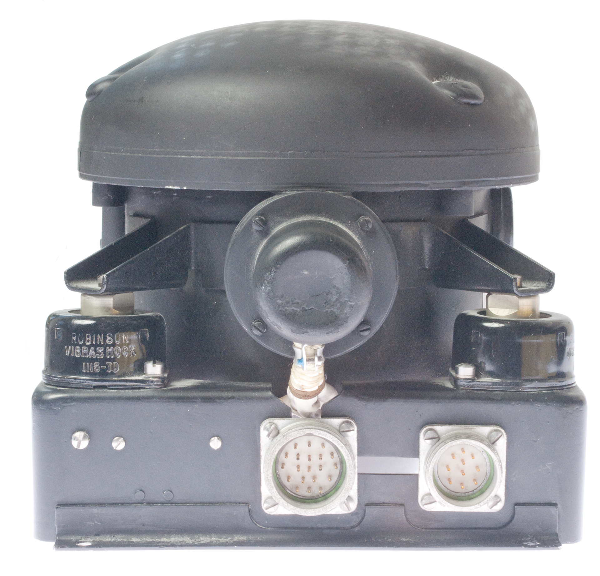
Connectors
Both panel connectors have coarse male thread on the shell and a single notch key-way at 12:00.
Cannon K02-16-10PN: 10 male pins: 0.805", OD 1"
Cannon K02-19-20PN: 20 male pins: 0.955", OD 1.882
Wiring
There are three cables coming out of the suspended part going to the base.
1. 5 wires going to A, B, C, D, E & F of the 10 pin connector. No other wires to this connector.
2. 9 wires going to terminal strips on base
3. 8? wires going to the 20 pin connector. A red, green and white wire also go to this connector from the base.
Patents (26 APR 2013 searching for this unit)
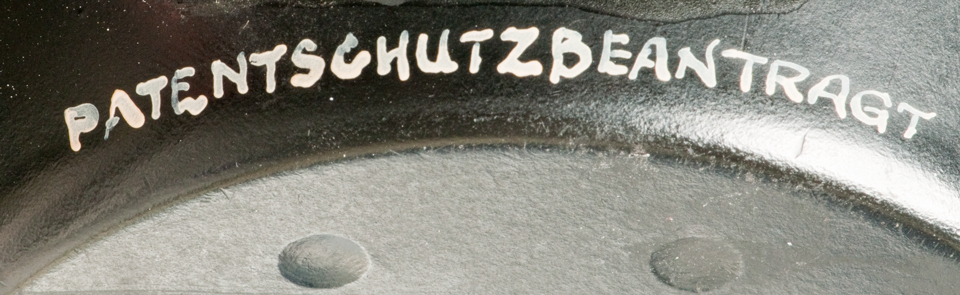
PATENTSCHUTZBEANTRAGT
Patent Applied for
2852859 Flux Valve Compensating System, M.C. Depp (Sperry Rand Corp), Sep 23, 1958, 33/319; 33/356; 33/361; 324/244 - 3 phase compass Transmitter - no Gyro
1887335 Automatic Pilot for Aircraft, L.B. Sperry (Sperry Gyroscope Co.), Nov 8, 1932, 244/78.1; 33/363.00Y; 74/5.00R; 91/51; 91/186; 91/363.00R; 91/375.00R
RE21071 Automatic Pilot for Aircraft, L.B. Sperry (Sperry Gyroscope Co.), May 2, 1939, 244/78.12195406 Automatic Pilot, B.G. Carlsen (Sperry Gyroscope Co.), Apr 2, 1940, 114/144.00R; 244/79
2003270
2270875 Gyro Vertical and Automatic Pilot for Aircraft, G.N. Hanson & O.E. Eaval (Sperry Gyroscope Co.), Jan 27, 1942, 244/79; 74/5.47; 318/649
2270876 Alternating Current Coercing means for Gyroscopes, O.E. Esval, A. and C.A. Frische Sperry Gyroscope Co.), Jan 27, 1942, 74/5.46; 74/5.60D; 74/5.8
2273769 Gyroscope, W.G. Harding & R.H. Nisbet (Sperry Gyroscope Co., UK), Feb 17, 1942, 33/326; 33/327
2283754 Automatic Banking means for Airplane Gyro Pilots, W.A. Mathews (Sperry Gyroscope Co.), May 19, 1942, 244/792301200 Gyromagnetic Compass, B.G. Carlson & B.A. Wittkuhns (Sperry Gyroscope Co.), Nov 10, 1942, 33/316; 33/327
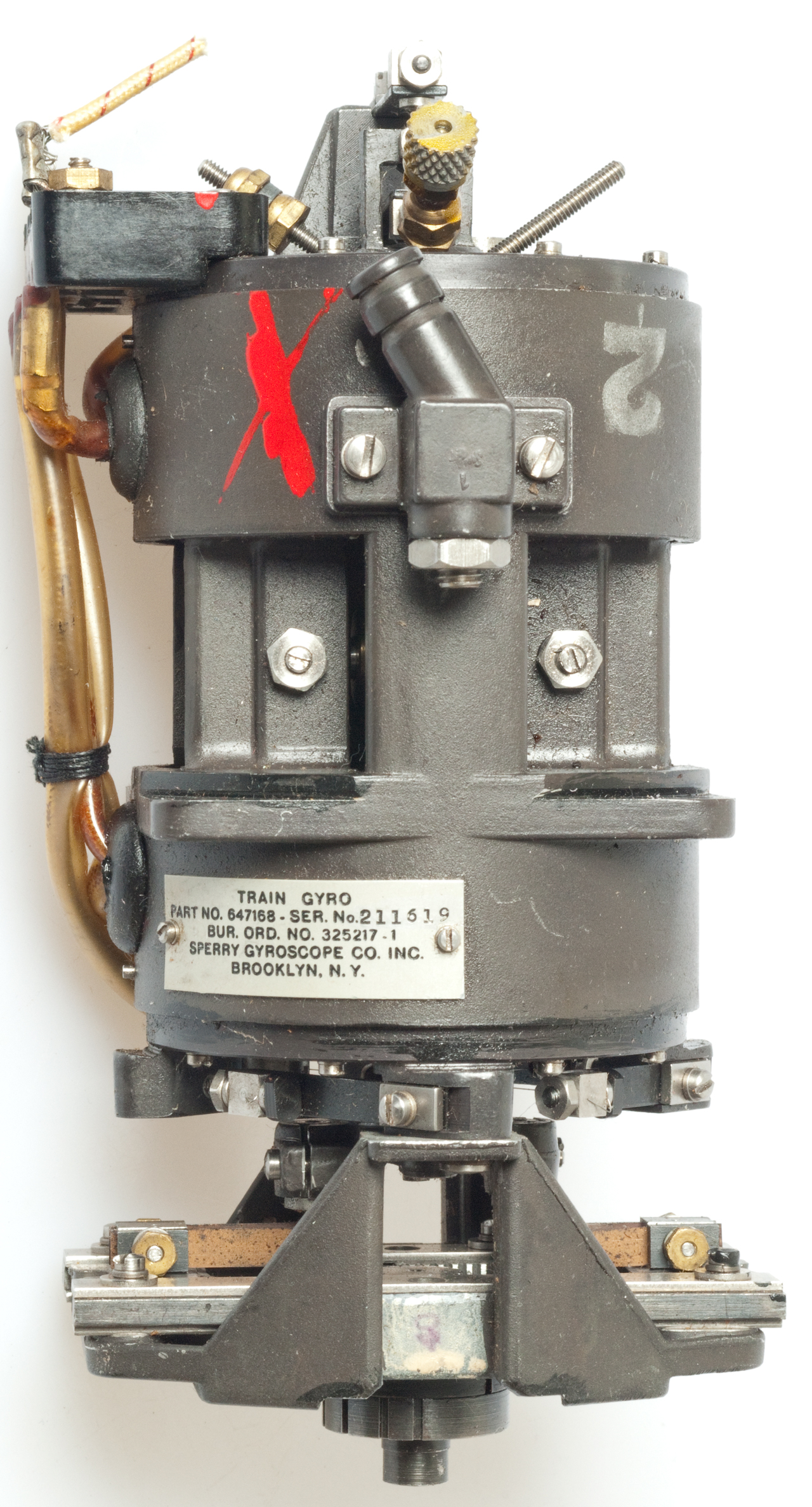
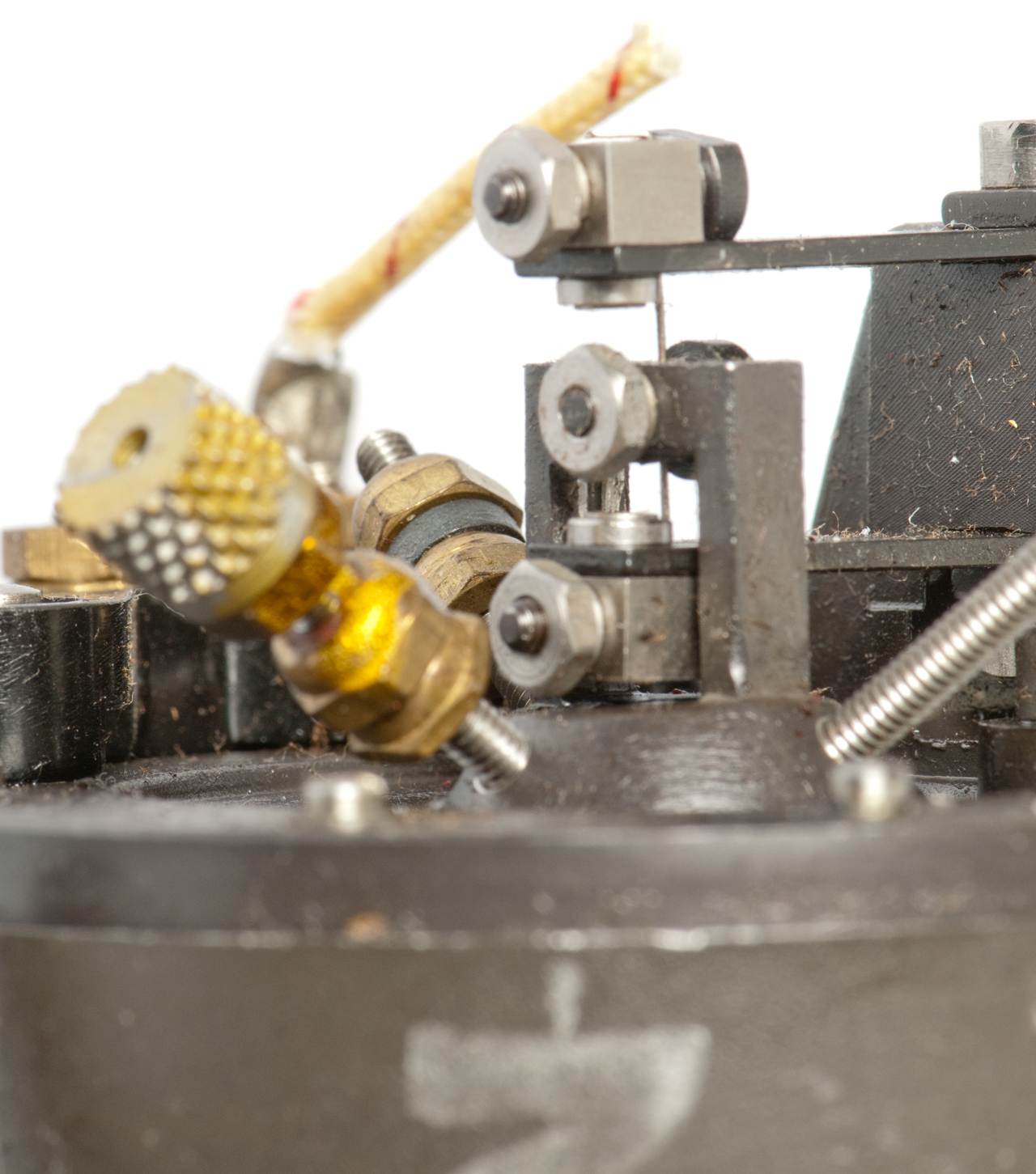
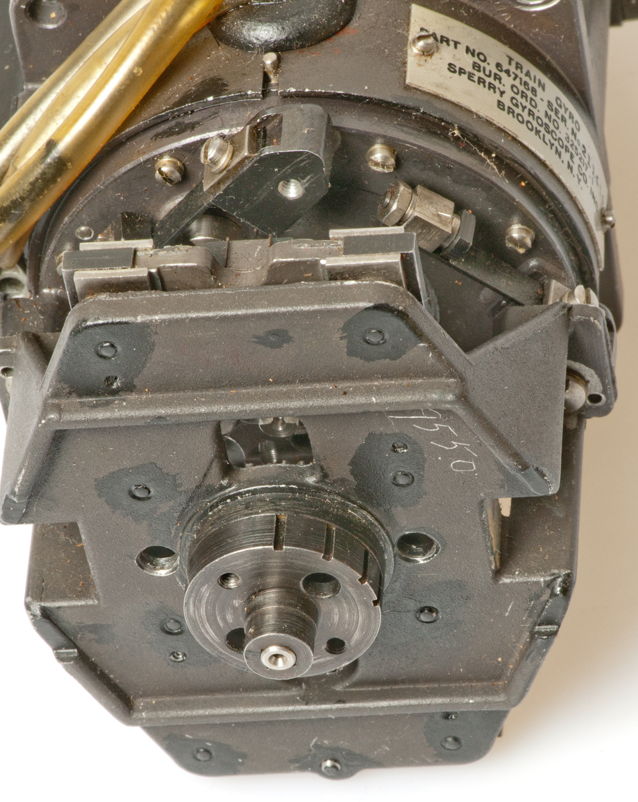
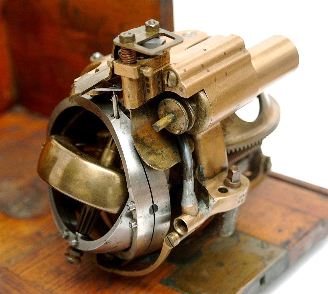
This was used on Naval ships as part of a gun director system. The gun would be "trained" in elevation and azimuth. The wheel is spun using air pressure and there's only one gimbal with very limited movement. It's constrained by support wires and the amount of torque can be adjusted.
Fig 1 The wires are for some type of output,
but what?
Fig 2 Two suspension wires.
Fig 3 Axial suspension wire on gimbal centerline.
Fig 4 Turning outer ring (fig 7) moves rack gear to
adjust torque resistance of gimbal.
Fig 5
Fig 6 Air nozzle points to the right
Wheel rotates clockwise.
Fig 7 Torque adjusting outer ring
YouTube: Train Gyroscope Sperry p/n: 647168
This small gyro was made by Northrop Corp, Precision Products Division and their p/n is 67514-301, NSN: 1430-00-186-7822
Huges Aircraft Co. p/n: 255490-1-1
sold by Electronic Goldmine as their p/n G7346 Maverick Missile Rate Gyro
The information sheet from Electronic Goldmine includes a circuit for driving the 400 Hz 2-phase electric motor.
It uses a 741 Op Amp as an oscillator and a couple of transistors (2N3904 & 2N3906 to drive one phase and uses a 1 uF NP cap across the other phase.
There have been many attempts to use gyroscopes to stabilize vehicles and it's ongoing.
584127 Motor Vehicle, E. Duaullette & E. Catois, 1897-06-08 - 2-wheels side-by-side
849270 Truck, Andrew Schafer, George Wanee, 1907-04-02, - Hand Truck with 3 axles to allow climbing stains [Bowels In Or Bowels Out? | Hannibal (2001)] - movie version has electric motor
1236030 Automonocycle, Louie G Wilson, 1917-08-07, - motorized unicycle
3145797 Vehicle, Charles F Taylor, 1964-08-25, - one wheel vehicle (Retro Car: YouTube)
20030205419 Riderless stabilization of a balancing transporter, Dean Kamen (Wiki), J. Field, John Morrell, Deka Products, 2004-08-24, -
20110231085 Electronic control system for gyroscopic stabilized vehicle, Daniel Kee Young Kim, Kevin Bretney, Andrew Shao, Andrew L. Tsang, Lit Motors, 2011-09-22, - 2-wheel motorcycle with enclosed cab - self balanced when stopped.
7979179 Apparatus and method for pitch state estimation for a vehicle, Michael T. Gansler, Segway (Wiki), 2011-07-12, -
9273961 Dynamically balanced flywheel, Daniel Kee Young Kim, Lit Motors, 2016-03-01, - vehicle stabalization
1022236 Gyroscopic top, Moses L Hawks, 1912-04-02, - classic toy gyroscope
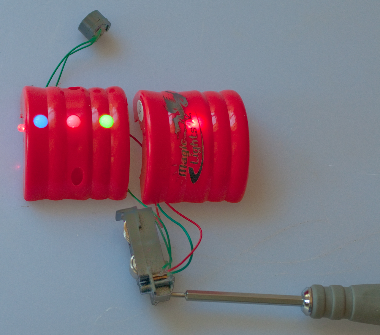
Super Magic Light Top Electronic Goldmine G19316
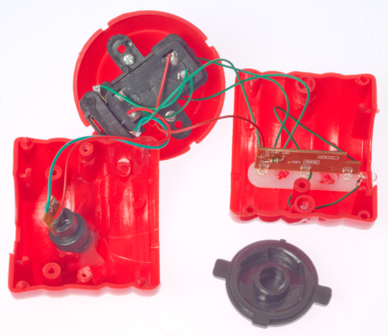
This top is amazing for the price (under $2). It contains a speaker, 4 LEDs and a red laser. Powered by 6 each 1.5 volt button cell batteries (L1131).
To replace the batteries:
These may be the same as: AG10, LR1130, LR54, SR1130, 389, 189 or RW89.
The speaker is the small round part that's mounted at the base just above the metal tip.
The battery holder also contains a switch that turns the top on when it's spinning and off when it slows down. Also in the battery holder is the chip that controls the blinking LEDs and Laser as well as making sound.
* remove two small (+) screws and seperate the two red half cylinders.
* remove the two small (+) screws to free the battery holder.
* remove the small (+) screw from the battery holder cover.
* Note the polarity of the batteries so you can install the replacements the proper way. (click on photos below to see larger image)
*Replace batteries.
*Replace battery cover.
*Place speaker into hole at bottom of top.
*Place battery holder with cover down and install 2 screws.
* Place one of the half cylinders over bottom cone and rotate until it engages a tab.
*Install the top drive plate with the two tabs on the cylinder split line.
*Install the other half cylinder and fasten with 2 screws.
YouTube Video http://www.youtube.com/watch?v=wmmi7RpDgy4
127619 Toy Spinning-Tops, Adam Linn, June 4, 1872, 446/223 - oldest gyroscope patent in this class
Infinity Spinning Top
When learning about the Mova Globe I learned that the inventor was considering a motor powered top, but instead developed the Mova Globe. One of the features is that it spins while sealed inside a sphere. That's to say the globe spins even though it has no connection to the outside (is floating in liquid). Seems to violate Newton's law about a reactive force. So when I saw a top that was motor driven I got it.
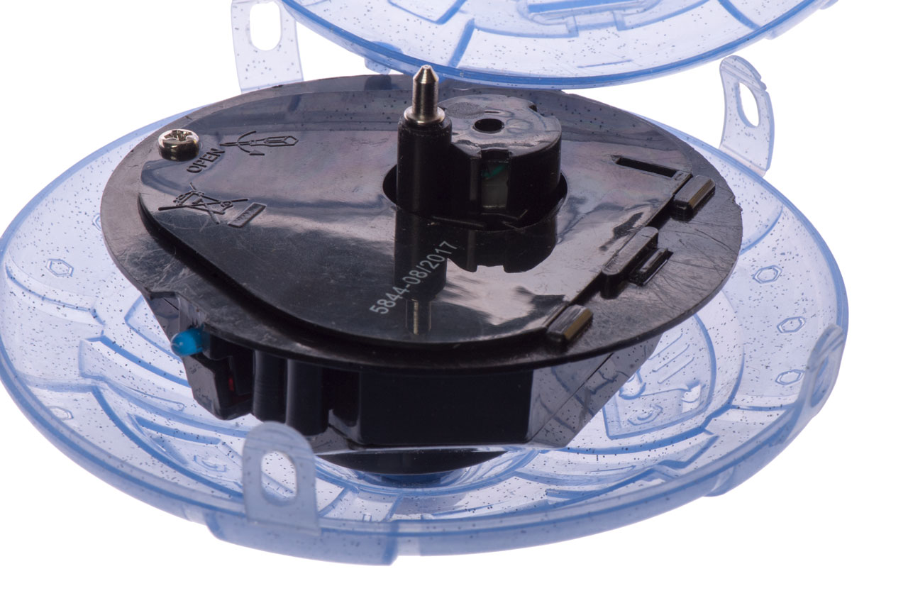
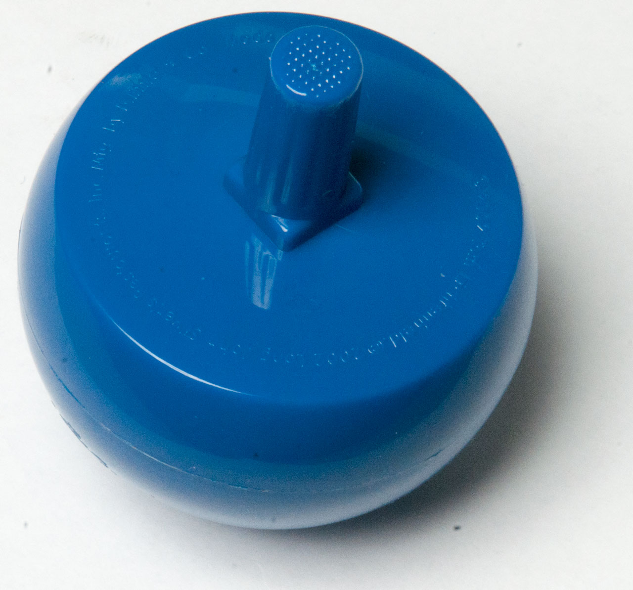
This is a top powered by three AAA batteries and has colored lights. Note that the Magic Top (above) has a wind up mechanism that's separate from the top and only spins for a short period of time. This top is powered by an electric motor and will spin as long as the batteries last.
There are four LEDs (Blue, Red, Green Yellow) that can be either off, dim or bright. The box says "32 different light patterns".
The motor spins the black plastic inner part relative to the outer blue shell. The inner mechanism spins and the outer shell spins in the opposite direction.
WO2016150038A1 Spin-activated electric top toy, 2016-09-29 - senses the direction of rotation and spins the motor in the appropriate direction. - This unit always spins the motor in the same direction.This unit has provision for a rechargeable battery and an on board charger. The Infinity Spinning Top uses primary batteries.
Fig 1
Fig 2
Fig 3 Standing on edge (gyroscope)
Fig 4 Cover removed showing battery access
(and motor?)
YouTube
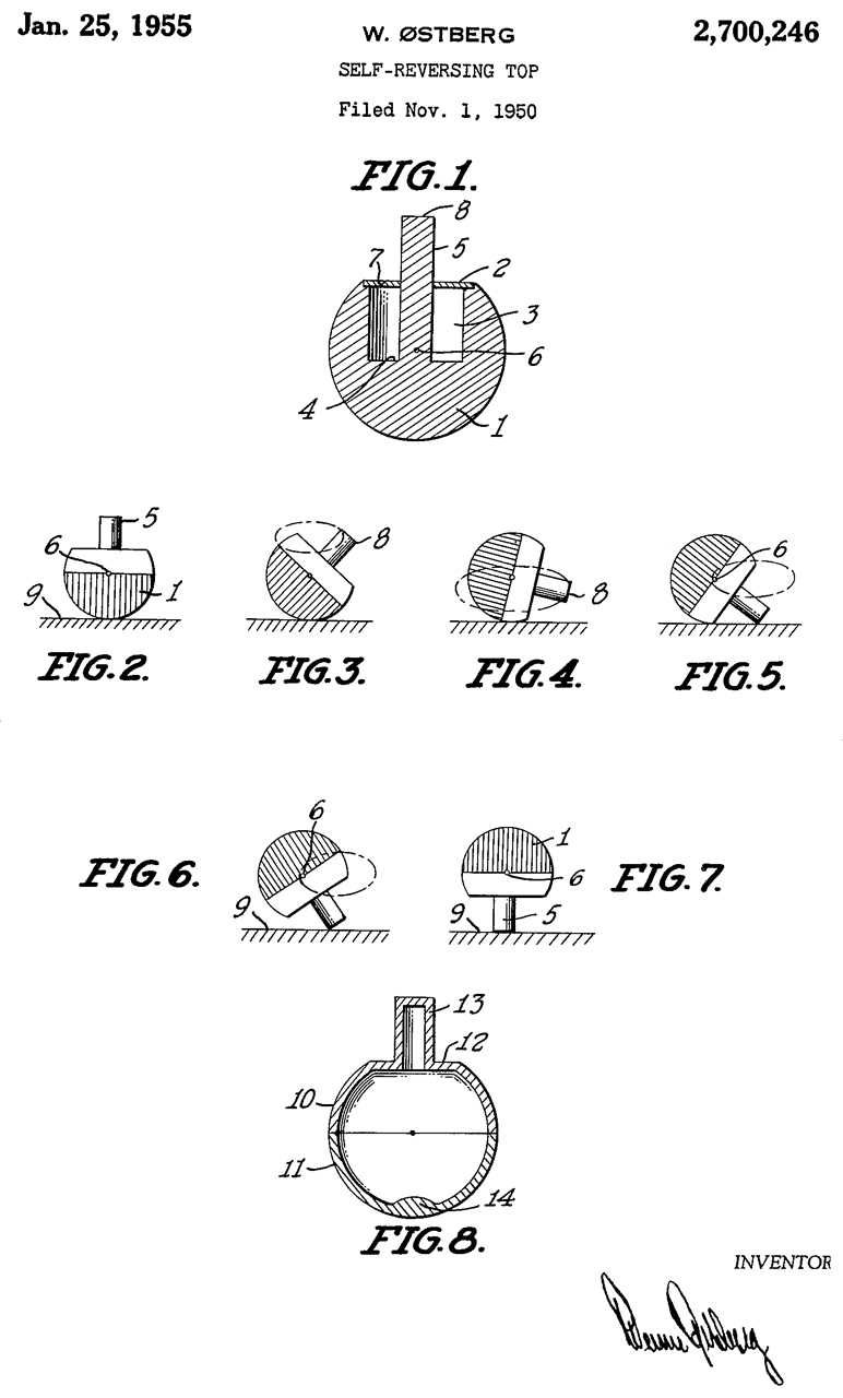
Tippy Top (Wiki)
Plastic
2700246 Self-reversing top, Phistberg Werner, App: 1950-11-01, Pub: 1955-01-25, 446/256; 428/11 -
I thought this was already on my web pages. I can remember the photo of Wolfgang Pauli and Niels Bohr (see Science Photo) playing with one.
There is also a US patent on it (Wiki lists a German 12.07.1892 patent by Helene Sperl, but this one was not manufactured).
Today these YouTube I discovered these YouTubes:
Zogg from Betelgeuse: Basic Saucer Physics (a video response to: Veritasium:Spinning Disk Trick - disk with off center hole).
also fromVeritasium: The Bizarre Behavior of Rotating Bodies, Explained - The Dzhanibekov Effect Wiki: Tennis Racket Theorem)
Motion of the Tippe Top Gyroscopic Balance Condition and Stability.pdf - 2005 heavy on physics & Equations
Wolfram Tippe Top - references
GR13083B Spinning top Werner Ostberg Tippe Top - The Spinning Top that flips itself over when it is spun! - spun on a plate with lip to contain top. Would be better if center of pewter plate was lower than edge, i.e. slight bowl shape.
Gyroscope.com - Metal Flip Over top
YouTube:
Forever Spin Top This is precision machined from Tungsten (Wiki) with a density 1.7 times that of lead, so you get a lot of mass in the size.
Toy Gyroscopes
1265899 Fly-wheel, John C Forster, 1918-05-14, - wire frame, fly-wheel made up of two sheet metal housings each with a lead wire weight. Early toy gyroscope.
1451818 Gyroscopic top and method of making same, John C Forster, 1923-04-17, - very similar to 1265899
This is a compass that indicates true North and works based on using a gyroscope that has it's spin axis parallel to the earth's spin axis (in the meridian).
794654 Gyroscope, Hermann Anschuetz-Kaempfe, Jul 11, 1905, 33/324 114/122 33/321 33/327 74/5.37- oldest US patent in class 33/324 (Gyroscopes), but came after a German patent for a very similar North Finding gyro. This is a pendulous gyro where the center of mass of the gyroscope wheel is below the center of the gimbals axis. Einstein was a paid expert witness in the patent infringement trial between Anschuetz and Sperry.
877034 Gyroscope, Hermann Anschuetz-Kaempfe, Jan 21, 1908, 74/5.44 114/24 33/318 33/324 74/5.46 - not North Finding
1186856 Gyroscopic apparatus, Elmer A. Sperry (Sperry Gyroscope Co), Filed: Jul 11, 1912, Published: Jun 13, 1916, 74/5.37, 114/122, 74/5.1, 33/321, 33/324
This is a stable platform, not a North Finding system. It uses multiple gyroscopes. Similar to 1253666 below
Applications 634594 & 634595
This is THE U.S. gyro-compass patent
1242065 Ship's Gyroscopic Compass' Set, Elmer A. Sperry (Sperry Gyroscope Co), filed: Sep 25, 1909, published: Oct 2, 1917, 33/325, 33/317.00R, 33/327
This may be the simplest North Finding, "true meridianal direction", compass. Fig 12 shows that the gyro needs to be placed at the center of mass of the ship for proper operation to minimize errors. Apparatus shown in Fig 1 to Fig 4 can be in the binnacle (Wiki).
1255480 Gyroscopic navigation apparatus, Elmer A. Sperry (Sperry Gyroscope Co), filed: Jun 21, 1911, Published: Feb 5, 1918
1279471 Gyroscopic compass, Elmer A. Sperry (Sperry Gyroscope Co), filed: Jun 21, 1911, Published: Sep 17, 1918,
33/324, 74/5.9, 33/344, 74/59, 310/74, 310/166, 74/5.4, 74/5.7, 33/317.00R
This is the key patent on the gyroscope itself, the other patents in this box are for the surrounding apparatus.
1296440 Repeater system for gyro-compasses, Elmer A. Sperry (Sperry Gyroscope Co), filed: Aug 23, 1915, Published: Mar 4, 1919, 33/325, 340/870.23, 340/870.34, 74/5.00R
1403062 Correction device for repeater compasses, Elmer A. Sperry (Sperry Gyroscope Co), filed: Jan 10, 1922, 33/325, 74/5.00R, 33/326 -
speed, heading & Latitude are sources of error and can be corrected.
TAN(C) = [K * COS(H)] / [E * COS(L)] = C
where:
C is a small (correction) angle
K is linear speed of ship
H(eading) angle relative to true North
E is the linear velocity on the Equator
L is the Latitude
1253666 Gyroscopic compass, Mervyn Edward Carrie, Franklin G Carrie, filed: Mar 24, 1903, Published: Jan 15, 1918, 33/323, 33/325, 33/320, 74/5.37 - no based on North Finding, but rather on a stable platform with multiple gyroscopes.
1279471 Gyroscopic Compass, Elmer A. Sperry (Sperry Gyroscope Co), Jun 21, 1911, 33/324 ; 310/166; 310/74; 33/317R; 33/344; 74/5.4; 74/5.7; 74/5.9; 74/59
Excellent early patent with references to Leon Foucault.
Note: The gyroscopic apparatus used by Foucault (maybe a pendulous gyroscope) will only work on land, it will not work on a vehicle such as a ship or airplane. The subject of this patent is to make a North Finding (gyro compass) that will work on a platform where there is variable acceleration in any direction.
1067716 Nautical Indicating Device, Owen L. Burdett, Jul 15, 1913, 33/320; 33/352 - allows determining Latitude or Longitude
This is an accessory for Wild theodolites that allows pointing the instrument exactly North. They were mainly used for setting up big guns (artillery) but also were/are used for laying out underground structures.
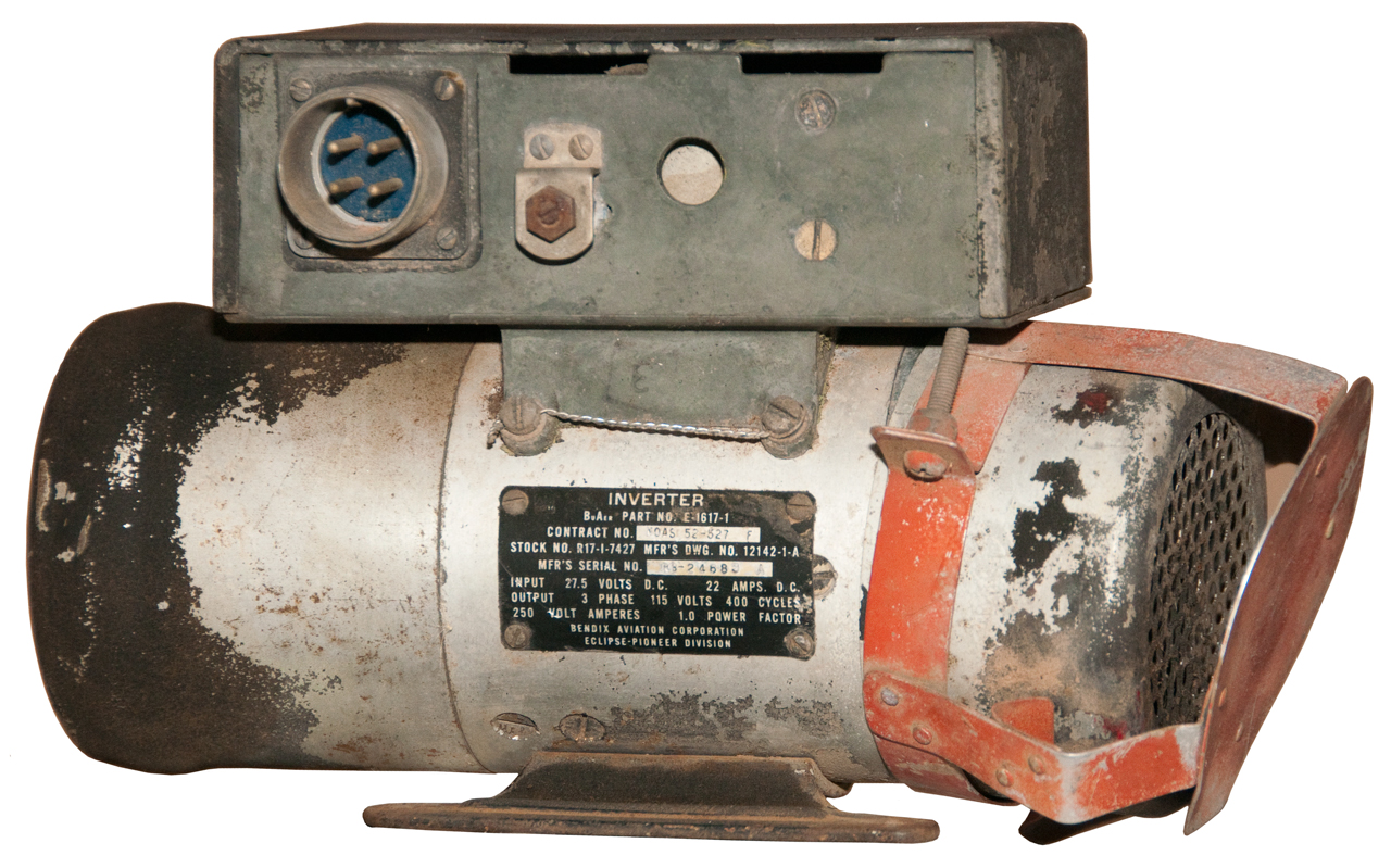
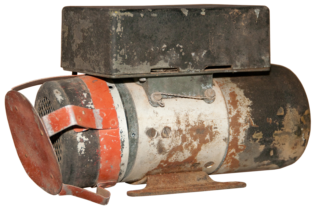
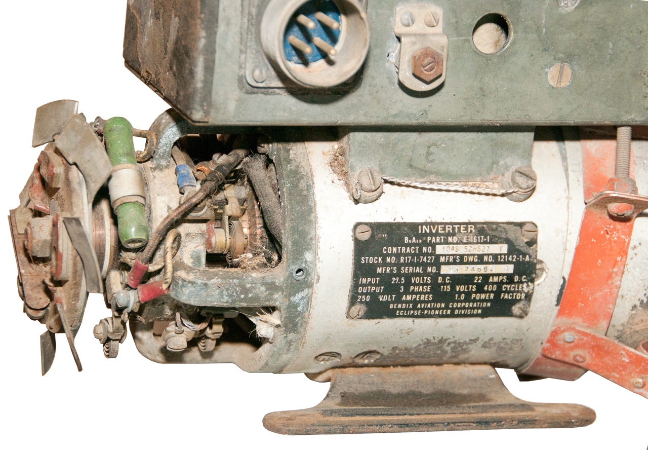
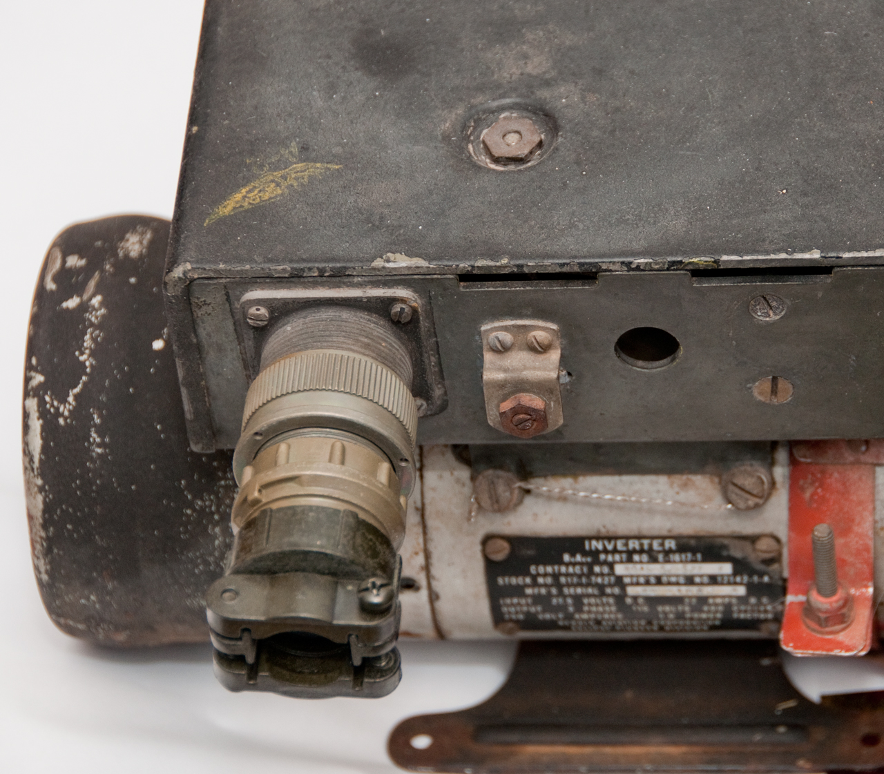
It runs on 115 VAC 3-phase 400 Hz AC power.
The internal gyroscope
was made by Perkin Elmer andhas the following characteristics:
moment of inertia: 1.86E6 g cm2/sec
RPM: 22,000
A flywheel 1 cm thick and with a radius of 1.09" spinning at 22,000 RPM would have the same moment of inertia.
If spinning at 16,000 RPM (the DC motor I have) a flywheel 1 cm thick and 2.37" diameter would have the same moment of inertia.
Note: the weight of a disk flywheel is equal to PI* t * R2 and the moment of inertia depends on [(RPM) * mass * R2] /2
So the final moment of inertia depends on R4 so a slight increase in the radius both adds weight as r squared and adds momentum as R squared.
These are generators where the magnetic field is supplied by the Earth.
1047157 Device for determining direction, Donald M Bliss, Dec 17, 1912, 33/362, 324/257 - a coil is motor driven and the Earth's magnetic field generates a voltage that can be used as a compass.
2206018 Earth Inductor Compass, P.F. Bechberger (Bendix Aviation Corp), Jul 2, 1940, 33/362; 324/247; 340/870.34 - 3-phase + triode amps
RE21970 Earth Inductor Compass, P.F. Bechberger (Bendix Aviation Corp), Dec 9, 1941, 33/362; 33/361; 324/247; 324/258 -2361433 Magnetic Compass, A.A. Stuart (Bendix Aviation Corp), Oct 31, 1944, 33/319; 33/361; 318/647; 318/654; 324/247; 340/870.33
RE22699 Magnetic Compass, A.A. Stuart (Bendix Aviation Corp), Nov 27, 1945, 33/319; 33/361; 318/647; 318/654; 340/870.332092032 Gyro-Magnetic Compass, E.A. Sperry & H.H. Thompson (Sperry Gyroscope Co), Sep 7, 1937,
33/316; 33/317.00R; 33/318; 33/356; 91/52; 91/375.00R; 244/792357319 Flux Valve Magnetic Compass, O.E. Esval & C.A. Frische (Sperry Gyroscope Co), Sep 5, 1944,
33/317.00R; 33/361; 33/362; 73/504.08; 74/5.47; 324/2472427654 Remote Reading Flux Valve Compass System, L.F. Beach (Purves Corp), Sep 23, 1947, 33/361; 324/247; 324/253; 340/870.33; 340/870.34
Includes a slave directional gyroscope
2574471 Gyromagnetic Compass, C.F. Fragola (Sperry Corp), Nov 13, 1951, 33/317.00R; 33/356; 74/5.4- 3-phase AC mag sensing + gyro
Pitch and Roll information are the output.
1984874 Gyro Vertical, R.E. Gilmor (Sperry Gyroscope Co), Dec 18, 1934, 33/328; 33/354; 74/5.00R; 340/870.05
2133793 Gyrovertical, W. Anscott (Sperry Gyroscope Co), Oct 18, 1938,
2018735 Gyrovertical - panel mount
2044151 Artificial Horizon - panel mount
1405807 Damping means for Gyroscopes, H.L. Tanner (Sperry Gyroscope Co), Feb 7, 1922, 74/5.44; 33/345 -
2044150 Artificial Horizon, B.G. Carlson, Jun 16, 1936, 33/329; 33/351 - instrument panel mounted
2219295 Pneumatic Errection Device for Gyroscopes, L.F. Carter (Sperry Gyroscope Co), Oct 29, 1940, 74/5.43 -
1934774 Gyro Vertical, E.A. Sperry (Sperry Gyroscope Co), Nov 14, 1933, 74/5.43; 33/327; 33/328 - electric motor or pneumatic - central not panel
2078560 Artificial Horizon - panel mount
1518892 Self-Damping Byropendulum, M.F. Bates (Sperry Gyroscope Co), Dec 9, 1924, 74/5.43 -
Calls:1982636 Air Driven Gyro Vertical, - instrument panel mount
1324482 Self-Damping Gyro-Pendulum,
2038531 Attitude Indicator for Aircraft, - panel mount
2183133 Artificial Horizon, - panel mount
When airplanes make a turn the size of the turn is measured in the time it takes to make a full circle. The most common rate is a 4 minute turn.
Note: When a fighter plane has forward facing guns and it's shooting at a target that's more or less fixed in comparison to the speed of the plane and after a strafing run the plane needs to make a full turn to engage it's target, about 4 minutes will have elapsed before the plane can again engage it's target. When the target is a submarine by the time a plane comes back for a second pass the sub will be submerged. This was one of the key reasons for the development of the gunship (Wiki) where the gun(s) are aimed at right angles to the centerline of the aircraft.
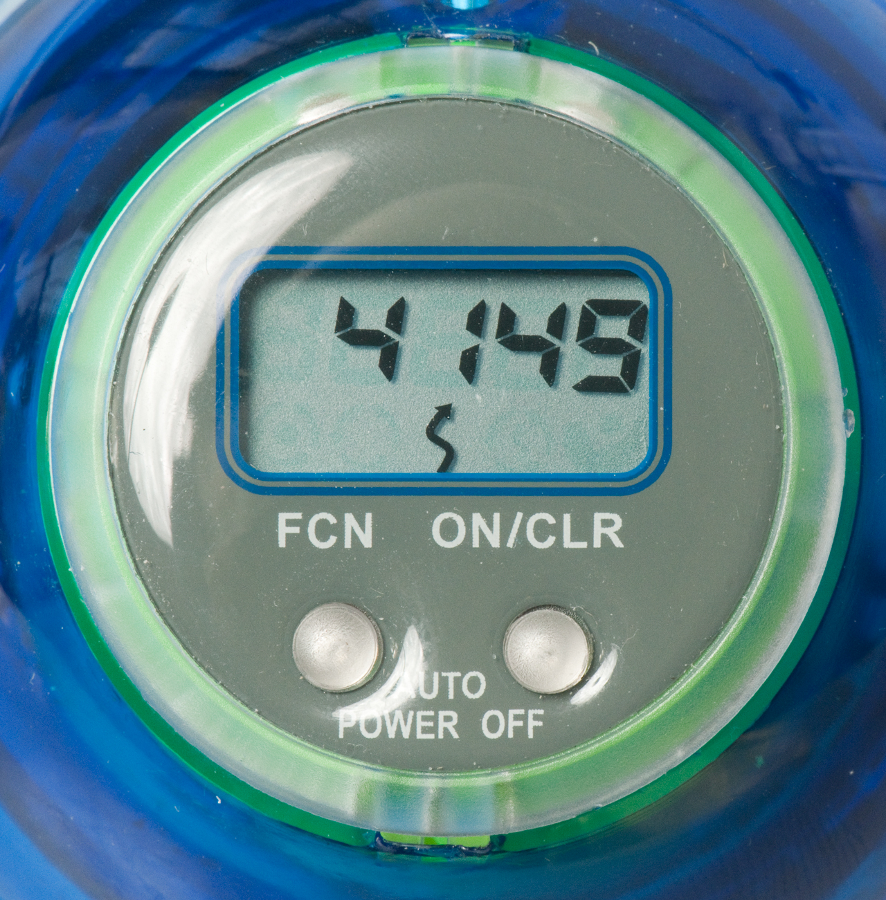
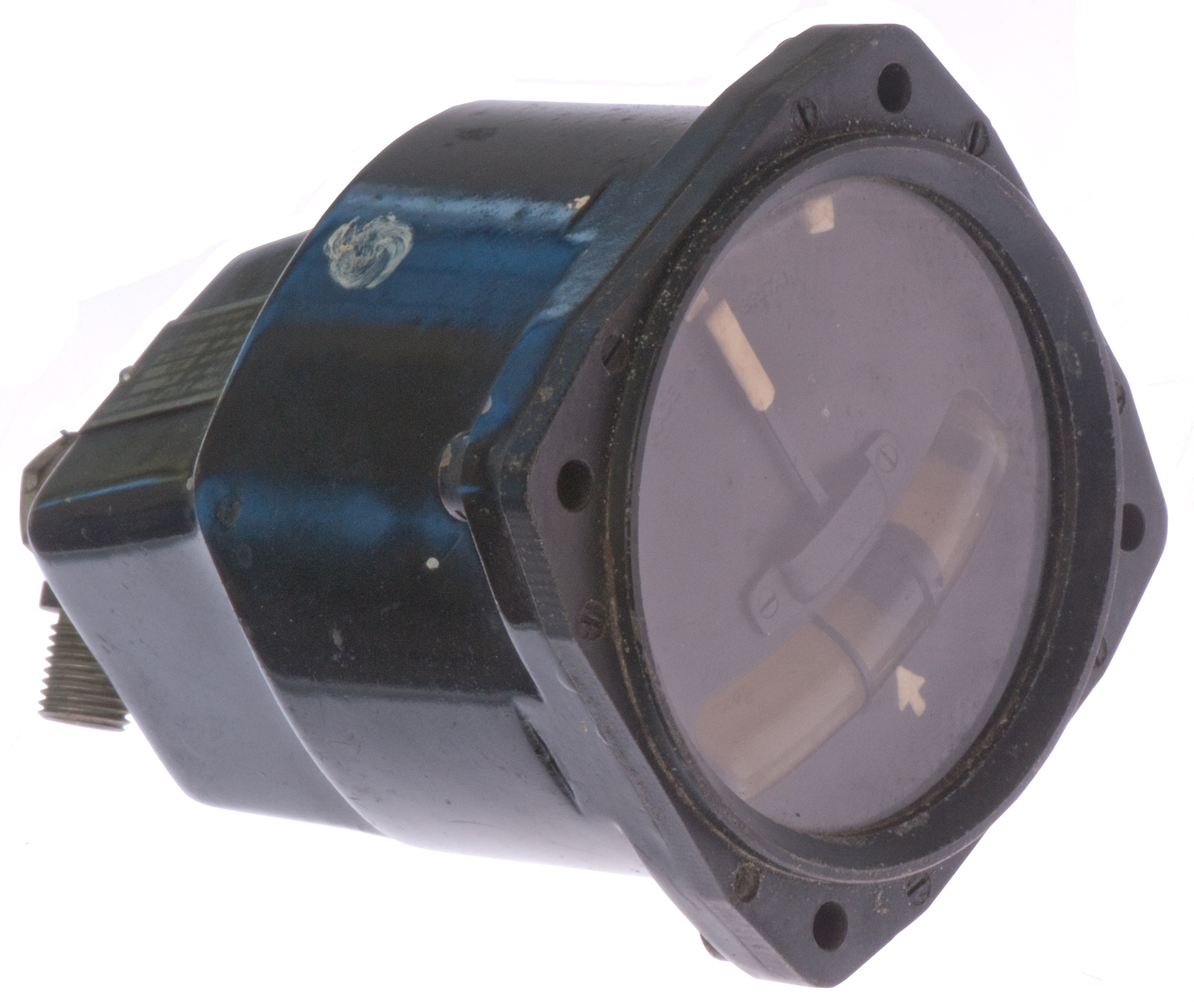
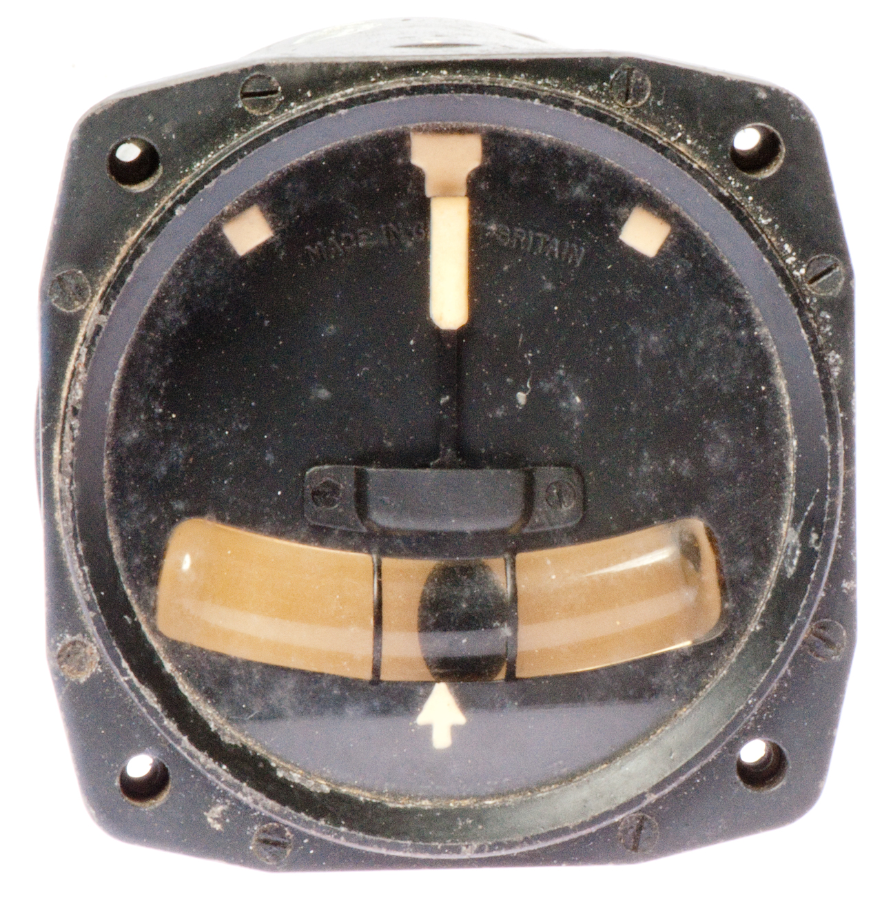
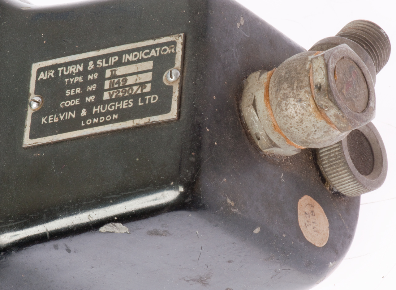
This turn and slip indicator is marked:
Air Turn & Slip Indicator
Type: II
Ser. No. 1149
Code No. Y290/F
Kelvin & Hughes Ltd.
London
Pointer at top connected to gyro frame.
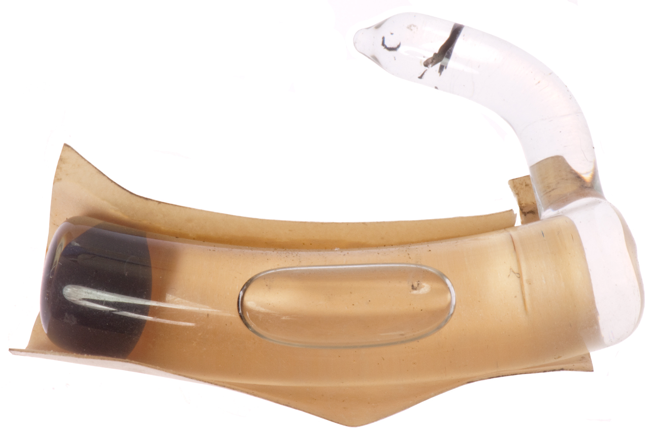
Weight in level glass at bottom.
Label
Male threads on vacuum connection.
Screen air filter for incoming air.
Level vial with metal ball.
Colored paper backing.
Front of instrument w/o level vial.
Front of instrument showing level vial (w/o backing paper).
Vacuum powered gyro.
Dash pot just behind front panel.
Screwdriver holding gyro frame to one side so
air turbine notches can be seen.
1836881 Flight Panel, E.A. Sperry Jr, Dec 15, 1931, 244/1.00R, D10/67, 248/27.1, 33/351, 73/178.00R, 116/280, 116/DIG.430
1982636 Air Driven Gyro Vertical, Carlson Bert G. (Sperry Gyroscope Company, Inc.), 74/5.43, 74/5.7, 33/329
2181250 Speed control for gyro rotors, Wladimir A Reichel, Bendix Aviation, 1939-11-28, - a vibrating element regulates the air flow or electrical current to maintain a set RPM.
2504114 Aircraft Flight Indicator,
2512607 Gyroscopic Flight Indicator
Course Gyroscope
Dwg NF 6100A, Ser. No. 6135
BUWEPS No. 10001-2047211--D MP3601
Date: 11-66
Mfd. by:
Electronic Specialty Co. (also made the N4100AA gyro)
Electronics Division,
Portland, Ore.
This was used on the Mk 46 Mod 0 torpedo based on introduction date of Mk 46 torpedo (Wiki) and date on this unit.
On one end is a label "FIRINGS" with 25 numbered spaces to write in a date (needed because the gyro needs rebuilding after each practice use).
The mounting ring has a notch so that gyroscope is properly aligned. Since the electrical connector has no method of holding a mating connector there must be a mounting sleeve that goes over the ring with the notch to hold the gyro down on the electrical socket. The electrical connector has a male and female locating pin that, plus the notch in the ring means, there's only one way to install the gyro.
12-3 Torpedo Gyroscope
The operation of the Mk 12-3 gyro used in the Mk 14 W.W. II torpedo is explained in Chapter 6 of OP 635 "Torpedoes Mk 14 & Mk 23 Types". Also how to set the balance nut for the local latitude is explained in: U.S. Navy Torpedo Gyroscopes Non-Tumble Type, OP 627(A), 1942 (Maritime.org). This is probably why the gyro is not built into the torpedo.
Chapter F. Control Systems of a Mark 15 Torpedo - very similar to the Mk 14 maybe even using the Mk 12-3 gyro
The Mk 12-3 gyro is mechanically spun up to 20,000 RPM and maintained at that speed by 125 PSI compressed air. The mechanical spin-up shortens the time between the start of preparation to launch and the actual launch. The output of the data computer is used to set the heading angle relative to the launch center line. The rudder of the torpedo is driven by an engine which gets it's input from the gyro.
The NF6010A gyro pot outputs the gyro heading relative to the start up center line bearing to drive the steering engine in the Mk 46 torpedo.
MIL-C-81064
Active dates: 21 May 1964 to 28 Apr 1998
Motor Voltage: 73 Volts 400 Hz.
Yaw Pot Voltage: either 45 VDC or 30 VAC 4800 Hz
Uncaging (P&L): 1 Amp for 15 ms (2 Ohm load at start) (this causes a resistor to break and mechanically allows the spring to spin up the gyro)
Wound and Caged Indication (H&J): switch contact
Static drift rate: <- 2 degrees/minute
Run time: 9 minutes (repeated 25 times)
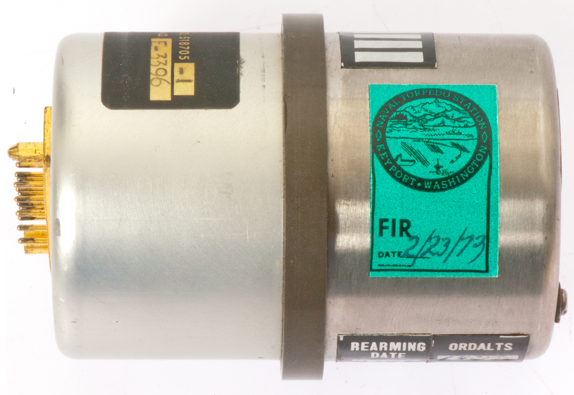
The notch in ring is to keep gyro case located in rotation and to protect the fragile slip ring (Wiki) wire contacts.
Connector Pin Out
Motor drive is 202 Ohms DC resistance, but should be driven with maybe 400 or 1000 Hz AC?
Pin
Function
A
Top of Pot
B
Bot of Pot
C
Wiper of Pot
D
Motor Drive
E
Motor Drive
H
switch
J
switch
L
squib
P
squib
F, K, M, P, R
no connection
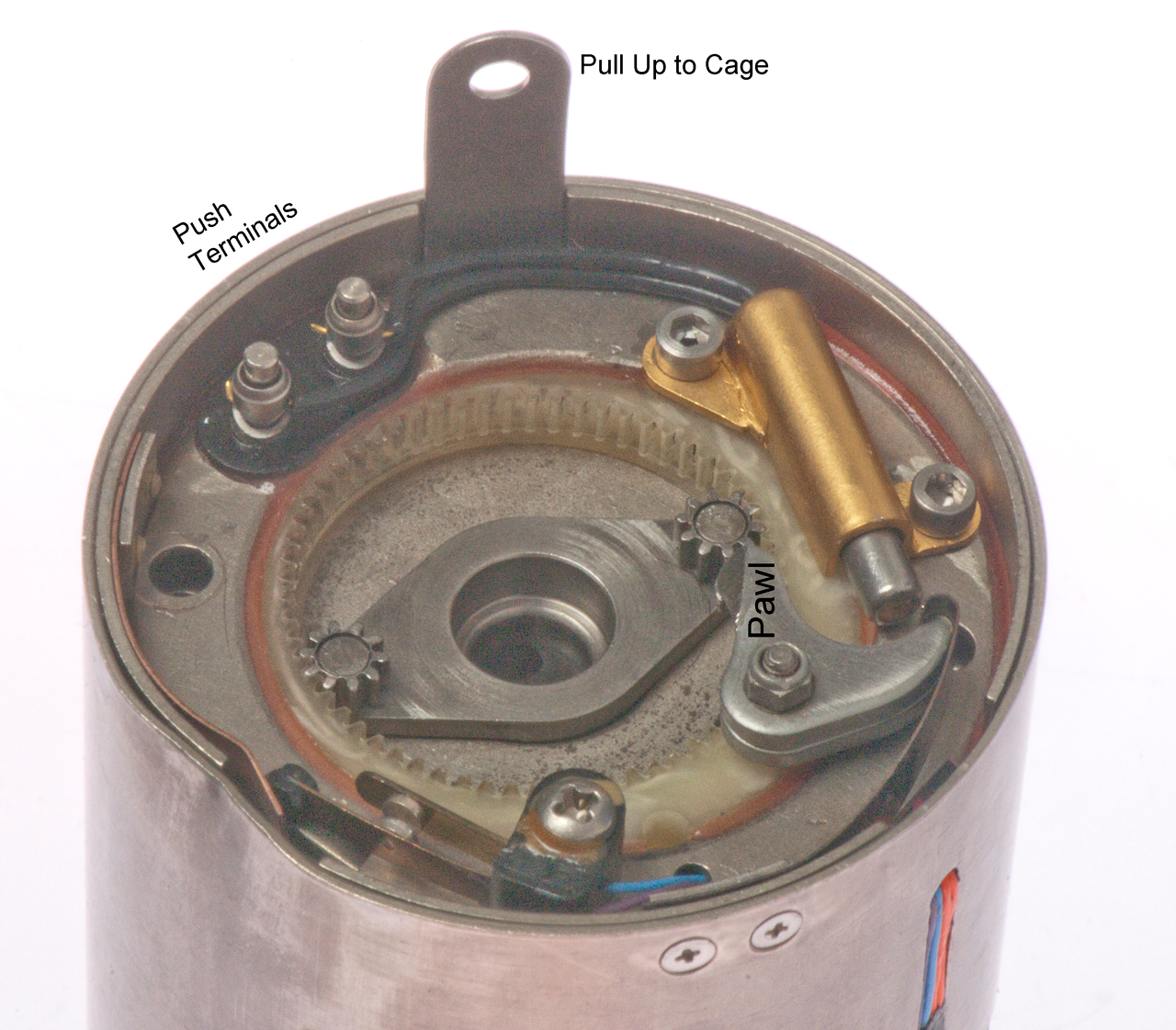
a 3/16" Allan wrench can be used to wind the ratchet assembly (Fig 1 & 2 below).
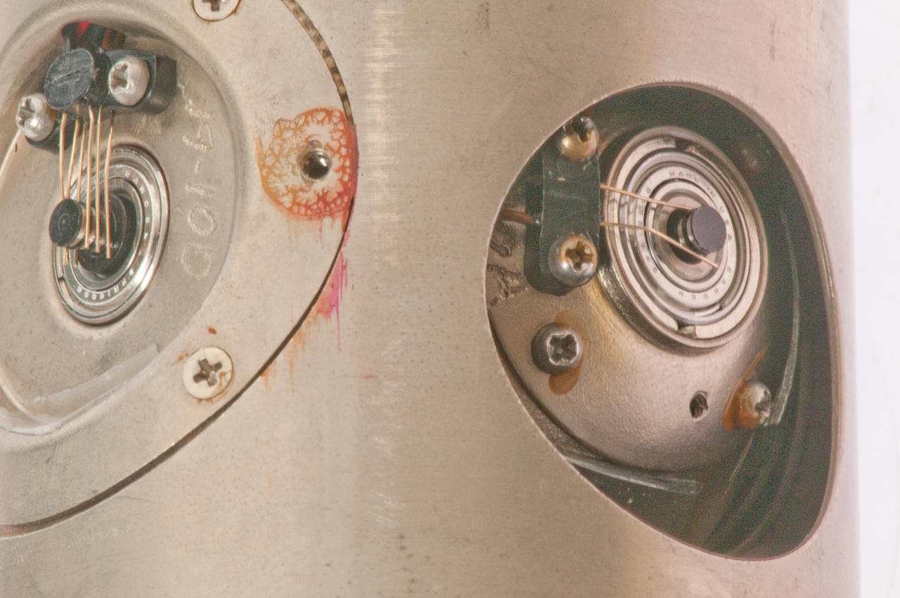
The sheet metal protrusion at about 7 o'clock slides up/down, Used to cage the gyro to allow installing the ratchet assembly for rewind. When down the gimbals are free.
Cylindrical squib at left floats in gold tube.
The Mk 484 Test Set calls this device a squib (Wiki)
Switch contacts H and J at 2 o'clock indicate spring wound when closed.
Note: the plastic internal gear teeth center line is not
the same as the center line of the gyro. Not sure why?
The sphere holds a 2-axis gimbal which holds the gyro.
one electrical contact (Center)
two electrical contacts (right) one misplaced in photo.
There's a sphere (outer gimbal) on the connector end with the ratchet assembly shaft going to the other end.
Notice tape covering hole just below slip rings.
There are other pieces of tape inside covering holes
between the squib and the inner compartment.
Why? maybe to keep carbon particles from exploded resistor from getting into spinning gyro, like happens with the Norden bomb sight carbon brushes.
three slip ring electrical contacts
(redundant one on each side = 6 fine spring wires)
3 contacts at left, two at right.
These are easy to bend if you handle the gyro.
Best to keep the sleeve with the locating notch installed.
Theory of Operation
The end opposite the connector has a label "Firings" and spaces for 25 dates to be written, implying the gyro is reusable but needs rebuilding after each test run.
The older 12-3 gyro used on the W.W.II Mk 14 torpedo had two mechanisms for spin up, one was a mechanical shaft from the sub and the other was an air jet, very similar to some of the Sperry gyros above. The gyros in some aircraft Inertial Navigation Systems may take a number of minutes to spin up to working speed (Wiki: INS). Although the air jet of the 12-3 or electric motor for this NF 6010A could spin up the gyro waiting a few minutes is not acceptable when you life depends on getting off a shot as quickly as possible.
In a like manner for the NF 6010A gyro there are two spin up mechanisms, first there's a clock work (wound spring) that can be wound using a 3/16" hex wrench. The part called a squib is very similar to the squibs used in sonobuoys that rather than exploding just releases a spring that does something. In this case the squib between P & L releases a plunger that when extended pushes the Pawl that releases the central ratchet (Wiki). The two black wires from the squib go to a pair of push down terminals so no tool is needed to remove and replace the wires, but a 5/64" hex wrench is needed to remove the gold color squib holder to allow replacing or rebuilding the squib. As the gyro spins up it ejects the ratchet assembly (Fig 2). the plain lid contains the ratchet assembly. The electric motor will keep the gyro spinning, but the spring changes the spin up time from many minutes (motor only) to maybe one second (spring).
After the spring has been released the switch contacts between H & J open to indicate that the gyro has already been spun-up and needs a rebuild. That may mean that the spin-up process has finished and the torpedo can be launched. It would also mean that a unit on a test bench had the spring unwound and it needs rebuilding.
When the sheet metal tab is pulled out it cages (Fig 1) the gyro aligning the spin-up hole with the shaft on the ratchet assembly (allowing it to fully seat. Note that when the gyro has the spin-up shaft installed it is caged in the starting position. That's important because any angle is referenced to that angle which is whatever bearing the center-line of the torpedo is pointing when the gyro is spun up. Once the spring is would the metal tab must be pushed back down to allow the gimbals (Wiki) to move freely.
Note: Unless you are working on the slip rings it's best to keep the sleeve with the alignment notch installed to protect the delicate slip ring spring wires.
Note: There is only one pick-off potentiometer (electrical pins A, B & C) so it can only output relative azimuth (bearing relative to the spin-up bearing).
There is a torpedo depth setting that has a ceiling, i.e. a ship launched torpedo can be set to attack targets below a ceiling that would prevent the torpedo from attacking the ship that launched it. But this is accomplished using a depth setting that works on the same principle as the one use on the Mk 14 torpedo. So depth is set based on water pressure (Wiki) and azimuth depends on the gyro. So the depth needs to be preset close enough for the a homing torpedo to acquire the target. A more sophisticated torpedo would have a decent-climb angle gyro in addition to the Course (bearing) gyro to allow a more direct path to the target.
There is a planetary gear (Wiki) between the spring and the gyro drive shaft. The purpose is to increase the speed of the gyro. Need to count some teeth to see the step up ratio.
I'm guessing that a 3D magnetic compass is not used because the metal of the launching sub would cause a large anomaly and if close to another vessel another anomaly and these anomalies would show up as heading errors. A gyro avoids that problem.
2874577
Gyroscope, O.W. Shirley ( (Iron Fireman Mfg Co, Portland, OR), Feb 24, 1959, 74/5.1, 74/5.00R - cage all gyro gimbals
2911832Gyroscope, Thierman Irwin B (Iron Fireman Mfg Co, Portland, OR), Nov 10, 1959, 74/5.7, 74/5.60D, 74/5.12, 74/5.47 - uses squib to release spring
3261214 Spring driven gyroscope, Amsler Clyde R, Waid Raymond L (Clary Corp), Jul 19, 1966, - 74/5.12
3290948 Gyroscope, George F East (Clary Corp), Dec 13, 1966, 74/5.60D, 74/5.00R - gimbal allowing max dia flywheel
3323379Spring driven gyroscope, Amsler Clyde R, 4 More » (Clary Corp), Jun 6, 1967, 74/5.14, 74/5.12, 74/5.7 - remote cage & wind
3434353Rate gyroscope, Brastow Edgar R, Schaberg Richard R, Voge Andrew (Clary Corp), Mar 25, 1969, 74/5.60D - spring to get started, work without precision motor RPM
3508447Gyroscope apparatus, Shirley Orie W (Electronic Specialty Co), Apr 28, 1970, 74/5.1 - remote caging (called by 3931742)
It appears a very similar form factor gyro is used in missiles that also has a mounting ring that's very similar.
For ones with short flying times they may be able to use only the spring wound spin-up and no sustaining motor.
The Mk 44 torpedo gyroscope has only the spring, no motor, so it had a reasonably short time from launch to end of run.
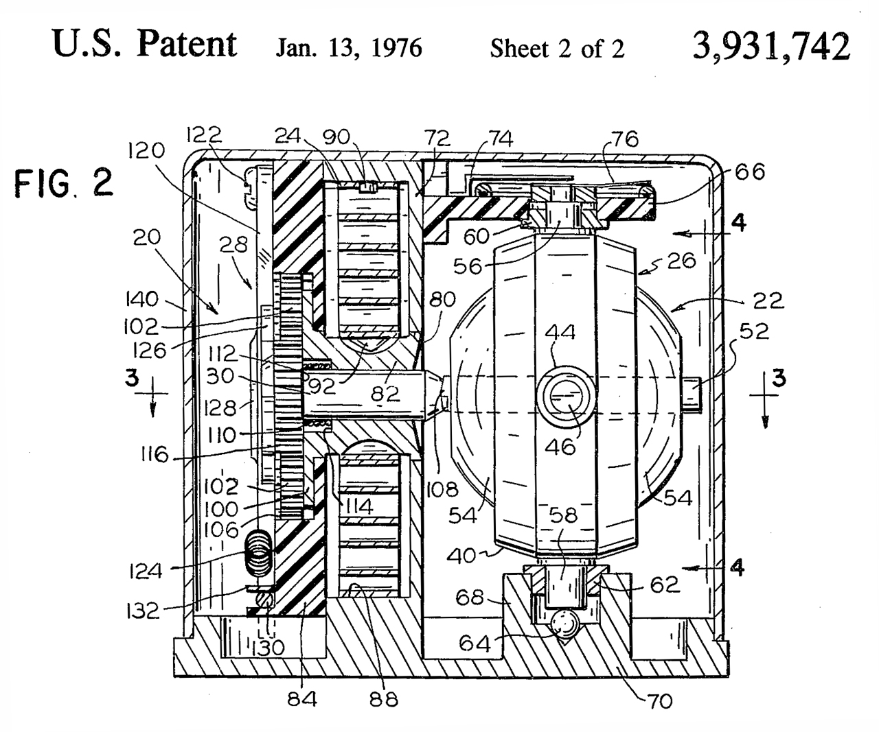
3931742 Gyroscope, Orie W. Shirley (Datron Systems, Inc.), Jan 13, 1976, 74/5.7, 185/37, 475/269 - speed multiplying spring drive
Also has a 4-lobe ratchet and in it's center a hex socket for winding.
The gyro drive includes a push-out feature.
Items 74 & 76 (upper right) relate to the pick-off pot.
Driver shaft 30 (ratchet assembly) is driven 3.1 times faster than the spring rate for a final speed of 27,000 RPM.
Fig 1 After spin-up & then Caged
Fig 2 Ratchet assembly
Youtube video of spin-up
Youtube video of Winding
Patents
Obry Device (Wiki) for Whitehead torpedo. Prior to this there was no azimuth control.
YouTube: The Devil's Device! - 128 Year Old Torpedo Gyroscopic Guidance Unit brought back to life @ 20,000rpm, 1:00 -
This may be the first patent after Léon Foucault (Wiki) named the gyroscope (Wiki).
562235 Steering mechanism for torpedoes, Ludwig Obry, Jun 16, 1896, 114/24 ; 74/5.12 - vertical clockwork gyro axis, not propulsion - can cause a circular path coming back to sender
621364 Device for starting torpedoes, Ludwig Obry, May 28, 1898, 114/24 ; 74/5.12
648878 Gyroscope for torpedo-steering mechanism, Ludwig Obry, Whitehead & Co, Dec 20, 1898, 74/5R ; 384/244
Frank M Leavitt (Bliss-Leavitt torpedo Wiki) 1904 - 1945
693871 Generation of power from compressed air, Frank M Leavitt ( E.W BLISS Co.), Feb 25, 1902, F02C9/28 - burns alcohol using 2250 PSI compressed air.
693872 Propulsion of torpedoes, &c., by compressed air, Frank M Leavitt ( E.W Bliss Co..), Feb 25, 1902, F42B19/00 - an improvement on the Whitehead torpedo (Wiki)
The Whitehead torpedo was manufactured by the E.W Bliss Co.
741683 Gyroscopic apparatus for steering torpedoes, Frank M Leavitt ( E.W Bliss Co.), Oct 20, 1903, 114/24 114/122 33/318 33/327 74/5.12 -
counter rotating props & first use of compressed air to spin gyro
748759 Automobile torpedo, Frank M Leavitt ( E.W Bliss Co.), Jan 5, 1904, 15B11/06, B25F5/00 - counter rotating props, turbine engine
768291 Gyroscopic apparatus for steering torpedoes or other uses, Frank M Leavitt ( E.W Bliss Co.), Aug 23, 1904, 114/24 - improved 741683 time delay for air spin-up
785425 Steering mechanism for torpedoes, Frank M Leavitt ( E.W Bliss Co.), Mar 21, 1905, 114/24 114/122 74/5R -
795045 Gyroscopic control apparatus, Frank M Leavitt ( E.W Bliss Co.), Jul 18, 1905, 114/24 114/21.1 74/5R - minimizing force from gyro to minimize precession
814969 Gyroscope spinning device, Frank M Leavitt ( E.W Bliss Co.), Mar 13, 1906, 114/24 114/122 74/5.12 - main prop shaft spins up gyro then air keeps it going
816019 Retarding device for automobile torpedoes, Frank M Leavitt ( E.W Bliss Co.), Mar 27, 1906, F01D15/10, F02C1/02 -
"...preventing. undue racing of the engine of a torpedo when the latter has been launched from a tube above Water."
825914 Ignition device for automobile torpedoes, Frank M Leavitt ( E.W Bliss Co.), Jul 17, 1906, F02K9/95, F42C15/32 - improvement of his 693872
880029 Ignition device for automobile torpedoes, Frank M Leavitt ( E.W Bliss Co.), Feb 25, 1908, F42C15/32, F02K9/95 - ignition only works after some number of prop turns
880030 Starting-valve for automobile torpedoes, Frank M Leavitt ( E.W Bliss Co.), Feb 25, 1908, F42B19/26 - frangible part is a cap or capsule
950550 Air-heater for automobile torpedoes, Frank M Leavitt ( E.W Bliss Co.), Mar 1, 1910, F02C6/16 - heats air after valve & heats air in tank near end of run
1022486 Heater for automobile torpedoes, Frank M Leavitt ( E.W Bliss Co.), Apr 9, 1912, 60/39.1, 114/20.1, 60/39.48 - water spray causes superheated steam
1044543 Stopping device for automobile torpedoes, Frank M Leavitt ( E.W Bliss Co.), Nov 19, 1912, 114/20.1 - stop if rudder locked to either side
1064349 Starting and stopping mechanism for automobile torpedoes, Frank M Leavitt ( E.W Bliss Co.), Jun 10, 1913, 60/325 - to prevent over revving the engine
1088079 Engine-governor, Frank M Leavitt ( E.W Bliss Co.), Feb 24, 1914, 60/409, 91/458, 91/47, 73/545 -
1088080 Driving mechanism for torpedoes, Frank M Leavitt ( E.W Bliss Co.), Feb 24, 1914, 416/129, 416/171, 114/20.1 - reducing gears drive the dual props eliminating miter gears
1088081 Turbine, Frank M Leavitt ( E.W Bliss Co.), Feb 24, 1914, 239/551, 239/568 - nozzle that can be manufactured and withstand the thermal shock - counter rotating props
1108196 Automobile torpedo, Frank M Leavitt ( E.W Bliss Co.), Aug 25, 1914, 60/694, 114/20.1 - uses exhaust pressure to force lubricate
1088911 Ignition device, Frank M Leavitt ( E.W Bliss Co.), Mar 3, 1914, 431/270 - the blank ignited cordite fuse for the heater pot is more reliable as for many practice runs
1124752 Governor for automobile torpedoes, Frank M Leavitt ( E.W Bliss Co.), Jan 12, 1915, 60/409 - improved version of 1088079
1308180 Automobile torpedo, Frank M Leavitt ( E.W Bliss Co.), Jul 1, 1919, 114/20.1 - propellers at bow to cut netting
1308181 Automobile torpedo, Frank M Leavitt ( E.W Bliss Co.), Jul 1, 1919, 114/20.1, 440/80 - double wide for higher speed 50 kt vs 35 kt for all of the above
Guidance
The Howell torpedo used flywheels for power that also acted somewhat to provide stability, but not very well.
562235 Steering mechanism for torpedoes, Ludwig Obry, Jun 16, 1896, F42B19/01 - vertical clockwork gyro axis, not propulsion - can cause a circular path coming back to sender
1401628 Hunting automobile torpedo, E.Meitner, A.C. Maby( Sperry Gyroscope Co Ltd), Dec 27, 1921, 114/23 - runs in circles after going a specified distance
1421854Gyroscopic apparatus for torpedoes, E.A. Sperry ( Sperry Gyroscope Co Ltd), Jul 4, 1922, 114/24, 74/5.12, 114/122, 114/20.1 - many improvements 3-phase servos
Early W.W.II Torpedoes
There were problems with U.S. made torpedoes early in W.W.II. (Wiki: W.W.II), Mk 14 & Mk 6 exploder,
American Heritage: Culpable Negligence (1980 Vol. 32, Issue 1). First hand account of circle problem. List of problems:
1.Running deeper than set.
2. Premature explosions.
3. Impotent contact exploder.
4. Circular-running torpedoes. (Tang sank itself (Wiki) Mk 18 Mod 1 electric torpedo (Wiki) with jammed rudder- led to the development of Anti Circular Running (ACR) in torpedos based on a gyro.
5. Magnetic influence exploder would only work is special conditions, most of the time it did not work.
Hellions of the Deep: The Development of American Torpedoes in World War II by Robert Gannon (reading May 2017)
There were 3 distinct launch platforms: Aircraft, surface ships and submarines. There were 2 distinct targets surface ships and submarines. A unique "torpedo" is required for each combination.
Maritime Organization - Torpedo related documents,
Note torpedo has a few meanings: a signal device for railroads, a static sea mine, a dynamic sea mine (various guidance systems)
953848 Exploder for automobile-torpedoes, Frank M Leavitt, Bliss Co., Apr 5, 1910, - contact exploder for dynamic sea mine
1295097 Mine-detonator, Carl Anderson, Feb 25, 1919, 102/422 - really a safe and arm (Wiki) device for a sea mine so it will not go off when it's not supposed to.
1382374 Method and mechanism for exploding submarine mines, Hudson Maxim, Jun 21, 1921, 102/417, 114/20.1 - referenced by 34 patents - uses movement of compass needle. probably for static sea mine, not torpedo.
1421854 Gyroscopic apparatus for torpedoes, Sperry Elmer A, Sperry Gyroscope Co Ltd, Filed: Mar 15, 1916, Pub: Jul 4, 1922, 114/24, 74/5.12, 114/122, 114/20.1 - complex multi gyro system needed for long range shots
1446276 Gyroscopic apparatus for torpedoes, Sperry Elmer A, Sperry Gyroscope Co Ltd, Filed: Aug 26, 1915, Pub: Feb 20, 1923, 114/24 - complex multi gyro system needed for long range shots
2409205 Bomb fuse, Graumann Raymond L, Oct 15, 1946, 102/226 - propeller on nose turns to arm, can also be used on torpedo - referenced by 14 patents
2945440 Discriminating fuze, Vogt Charles C, Filed: Dec 16, 1949, Pub: Jul 19, 1960, 102/420, 102/412, 102/265 - for air dropped static sea mines
The Mk 44 (Wiki) is a light weight acoustic antisubmarine homing torpedo (these are typically 12-3/4" diameter) and can be launched from surface ships and aircraft. Counter rotating props powered by an electric motor.
Designed in 1953 and some were still in use up to 1993 when they were retired rather than replace the batteries.
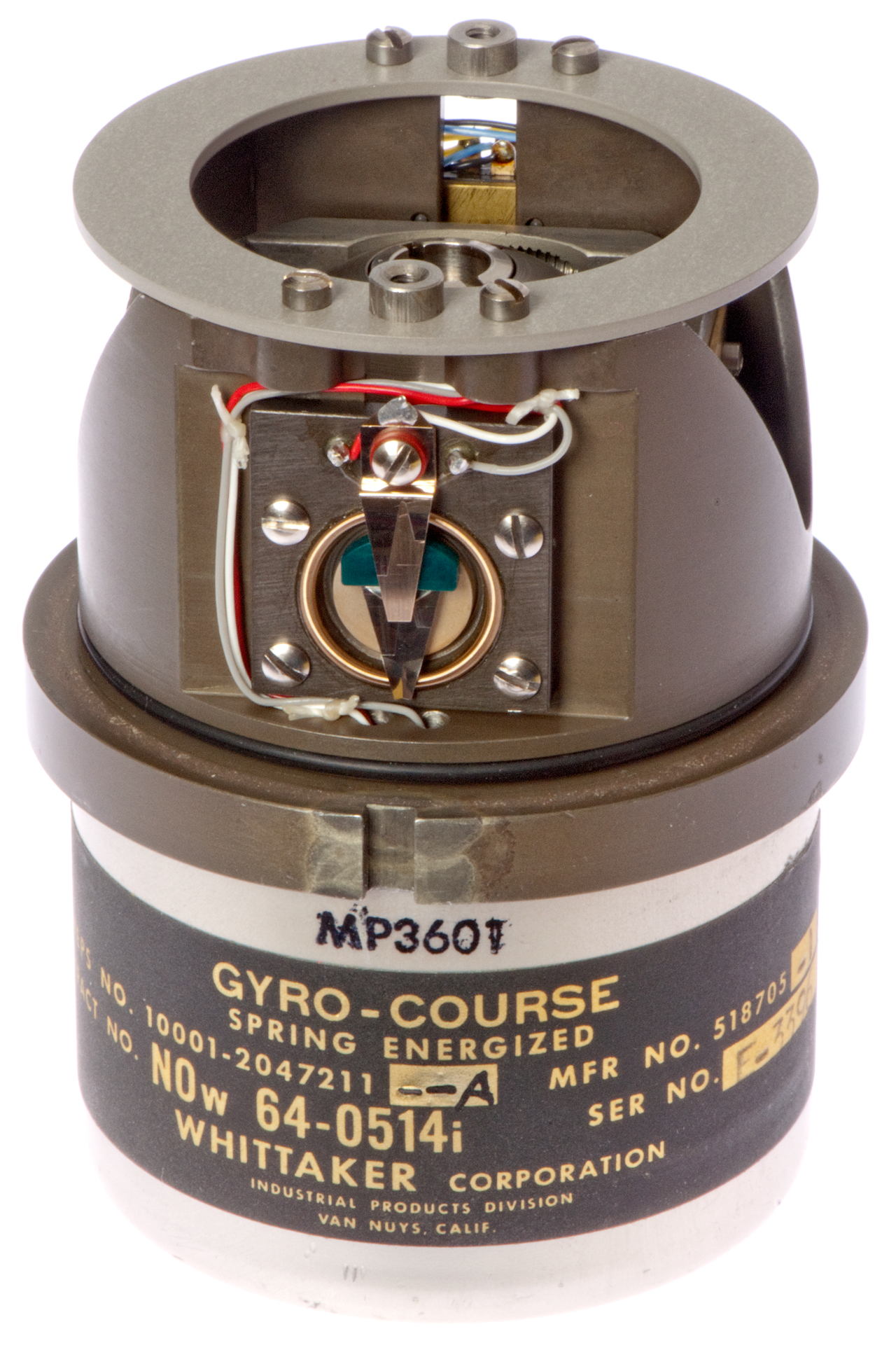
The label on this unit:
MP3601
Gyro-Course
Spring Energized
BUWEPS No. 10001-2047211--A
Mfr No. 518705-1
Contract No. NOw 64-0514i
Whitaker Corp, Industrial Products Div, Van Nuys, Calif.
There is an open circuit between pins L and D that may indicate that this gyro only has spring power, i.e. no AC motor like the gyro on the Mk 46.
Fig 1
Fig 2
Rearming sticker:
Naval Torpedo Station Keyport Washington
FIR 2/23/73
Fig 4 Connector end.
arrow is direction of squib plunger force that pushes pawl
from ratchet wheel releasing spring.
Fig 3 Rearming Date 2/23/73 ORDALTS (ORDance ALTeration Specification) 10256
Fig 5 brown wires connecting to squib go to screw terminals
Spring wound switch at lower center looks like a commercial
Microswitch type.
Fig 6 Plain End inside slip-rings
Fig 8 Plain End inside pick-off pot
Fig 7 Plain End inside
Patents
spring-driven gyros are mostly used in missiles that have short run times, maybe air-to-air types (Wiki- typical run time = 7.22 to 72 seconds)
2732721 Spring-driven gyroscopes, Thomas O. Summers, filed: Aug 2, 1954, issued: Jan 31, 1956, 74/5.41, 74/5.12 - a case erected, two-gimbal flee gyroscope for missile, spring connected to rotor, continues to accelerate rotor as means to erect
2982140 (spring-energized)Gyroscope assembly, Bennett William E (Telecomputing Corp), May 2, 1961, 74/5.12, 74/5.7, 123/185.14, 114/24 -
3232121 (spring-energized)Gyroscope, Todter Warren H ( Model Engineering & Mfg Corp), Feb 1, 1966 ,
3434354 Spring driven gyroscope, Voge Andrew (Clary Corp), Mar 25, 1969, 74/5.12, 74/5.7 -
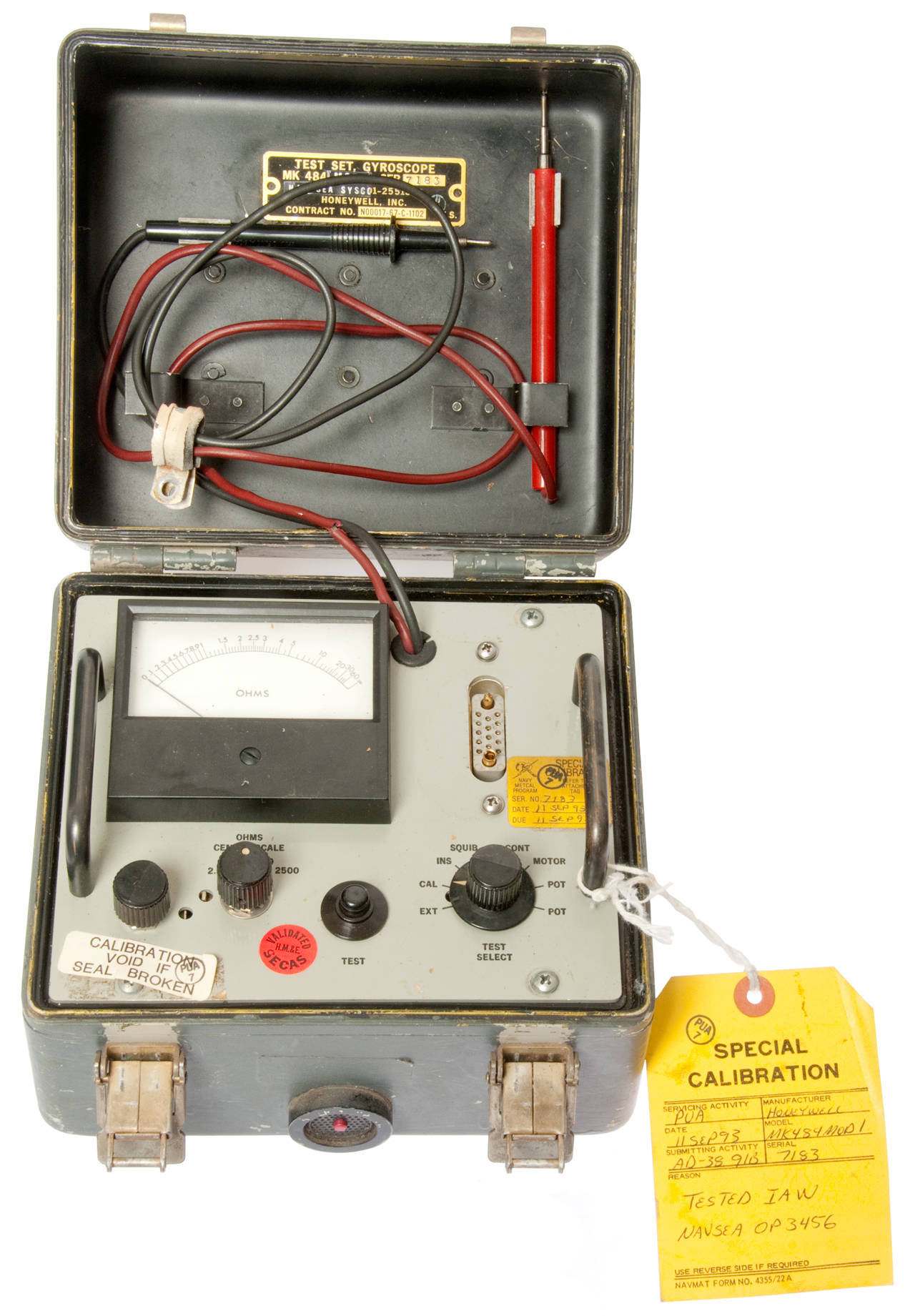
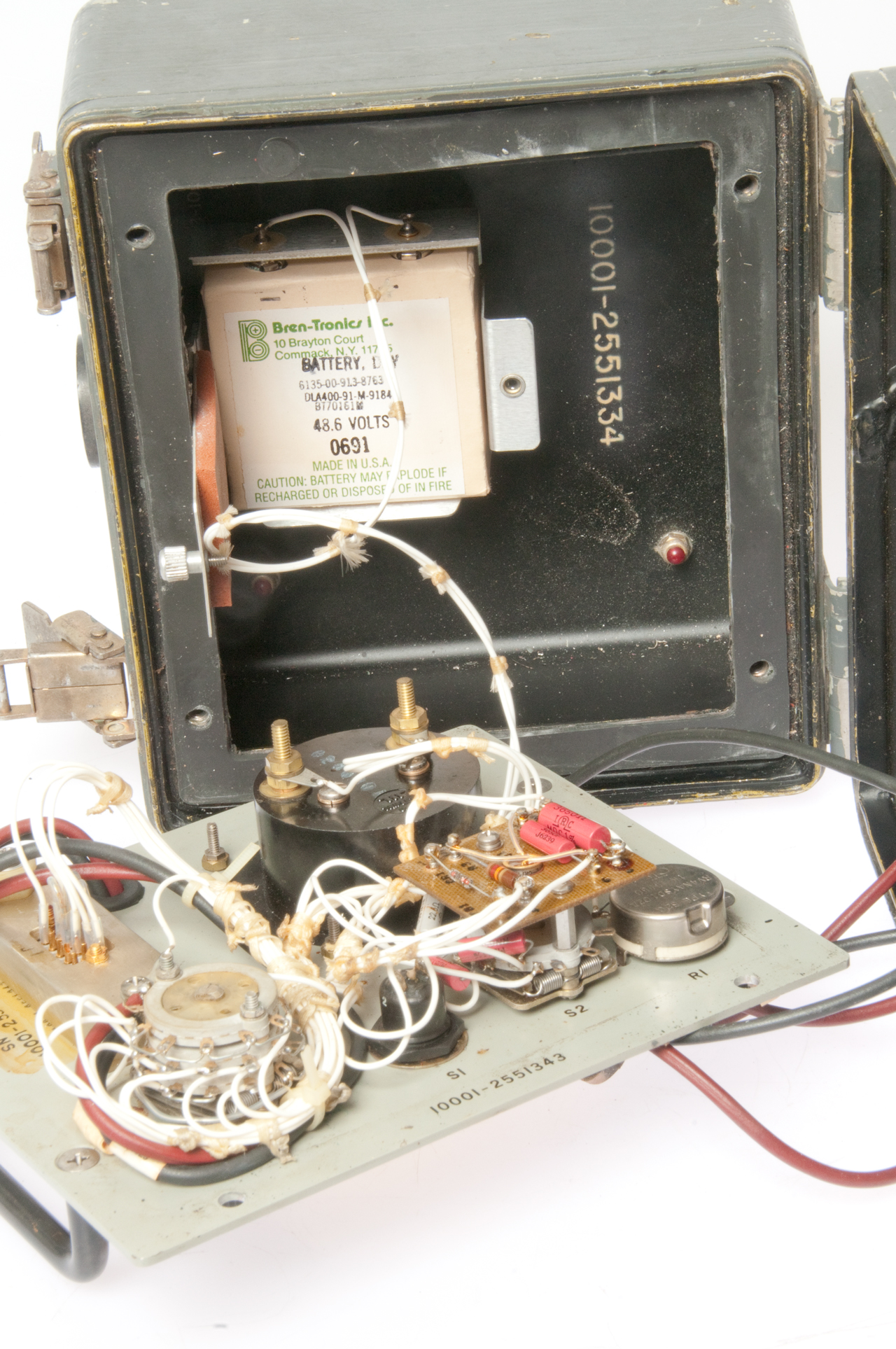
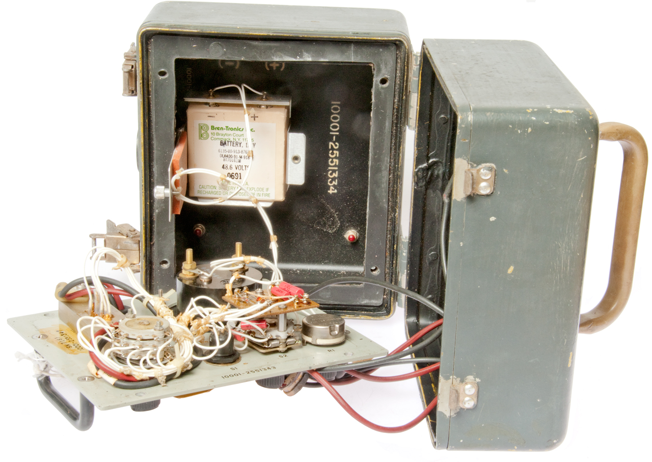
I think this test set was designed for the NF 6010A gyro (above).
Built to mil standard: MIL-T-82456
SW515-AM-MEB-010
Fig 1 There's a sticker with Mod 1 behind black wire.
Fig 2
Fig 3
Battery Dry
6135-00-913-8763
BT70161M
48.6 Volts
0691
Odd voltage, not 45 Volts which would be 5 9V batteries, but
slightly more, yet it's a "Dry" battery meaning not rechargeable.
Uses large snaps and they may have the same center to center distance as the No. 455 battery (45 Volt).
Separate web page for Gyroscopic North Finding
Wild Heerbrugg ARK 1 Gyro Aiming Circle - a North Finding Surveying instrument
So far I haven't got one of these, but don't have a lot of motivation since it was mostly a marketing phenomenon. The Wiki page says "Many factors have been put forth to explain the Norden's poor real-world performance." A number of times "precision horizontal bombing (Wiki)" was tried in W.W.II and every time it failed and was given up. "Carpet bombing" (Wiki) was then used. The poor performance is consistent with the modern understanding of ballistics. There are many factors that need to be taken into account that were not even considered in W.W.II so there's no way torpedoes or big guns could be accurate at long ranges.
For more see my Aircraft, Mk 20 Mod 4 Gun-Bomb-Rocket Sight (A-1 Skyraider, AC-47 Spooky), Navy Mk 18 Gyro Sight (for air-to-air combat). Note that the Mk 20 is called a "gun sight", but it was also used for dive bombing (not horizontal bombing).
Horizontal bombing has never been accurate and never will be when dumb bombs are used. Dive bombing (Wiki), pioneered by the German Junkers Ju 87 (Wiki), was accurate. In the book Wired for War it's suggested that smart bombs don't always hit the desired target.
When learning about W.W.II torpedoes (range & accuracy, Big Guns Disconnect) I found that the stated range far exceeded the accuracy. While some torpedoes had ranges (they could go that far) of more than 10,000 yards, pretty much all hits occurred at around 500 to 1000 yards. It's my belief that the same applies to the "range" of the big guns on battleships. The idea that a moving battleship can hit another moving battleship at a range over 10,000 yards makes no sense.
The Aerial Bomb by Col S R Stribling, January, 1943, Flying magazine, vol 32, no 1, pp 38-40, 112, 114. (web page, jpg) The diameter of the crater left by a 1000# bomb is less than 60 feet in diameter.
I think that means that a cone above that diameter with maybe a 45 degree angle is the space that gets the most destruction. During W.W.II using "precision bombing" the miss distance was measured in miles.
In a similar manner big guns or guns that fire at high angles have fundamental problems with accuracy making them very poor at hitting anything at their stated maximum range. See:
FN-FAL: Ballistics - note that G. Bull (Wiki: SRC, Base Bleed, Fineness ratio, GC-45 Howitzer, G5 Howitzer) developed long range accurate artillery by using a smooth bore
Torpedo: Range & Accuracy, Big Gun Disconnect
3886009 Projectile containing pyrotechnic composition for reducing base drag thereof, Walter J Puchalski, US Army, App:1973-12-13
4213393 Gun projectile arranged with a base drag reducing system, Nils-Erik Gunners, Rune V. Hellgren, Torsten Liljergren
4807532 Base bleed unit, Kurt G. Andersson, Nils-Erik Gunners,Yngve L. Nilsson, 1989-02-28, -
SE507777C2 Artillery shell firing method, Foersvarets Forskningsanstalt, 1998-05-28
The above means that as of W.W.II torpedoes, big guns and bombers were far from optimized for their task and that in turn means that a huge amount of money was poorly spent. For example torpedoes with much shorter range would cost less or more of them could be carried on a sub. The money spent on bombers and the bombs was pretty much all wasted.
Deconstructing the myth of the Norden Bombsight - "During the war, the device proved to be a failure, yet the rhetoric and altruistic belief in the bombsight's ability to save lives persisted."
Sperry S-1 sight and A-5 autopilot
TED: Malcolm Gladwell: The strange tale of the Norden bombsight - when attempting to bomb a 757 acre chemical plant in Germany over the course of 22 bombing missions (85,000 bombs) 0nly 10% landed inside the boundary and of those only 16% exploded. The German copy of the Norden also did not work. In the first Iraq war 2 squadrons of F-15E fighters were tasked with eliminating the Scud missiles, but the audit showed they did not hit any scuds. The predator drone is the grandson of the Norden bombsight, but the final problem is finding the pickle barrel. On August 6, 1945 the Enola Gay used a Norden bombsight to drop an atomic bomb but the 800 feet miss did not matter at all. The Navy developed the Norden bombsight, but after testing showed it could not hit a ship at sea they gave up on it and developed dive bombing.
Dive Bombing in a World War 2 Aircraft U.S Navy Training Film - 1943 (23:44) -
USAAF A-36 Apache dive bombers attack near Rome -1944 (5:41) -
Example from gaming:Grand Theft Auto Online: Learn how to be a Dive Bomber - America's Pursuit of Precision Bombing, 1910-1945 (Smithsonian History of Aviation and Spaceflight Series) -
this book is filled with technical details of how poorly bombing worked. Most of the bombs had crater diameters on the order of tens of feet but miss distances of many thousands of feet. Ironically a Norden bombsight was used to drop the Fat Man atomic bomb where it did not make any difference where it fell. Some of the data in the above TED talk by Gladwell came from this book. It turns out that a small error in the elevation above ground causes a miss of many times the crater diameter. An attempt to fix that was the development of radio, and later, RADAR altimeters that were coupled to the bomb sight.
Ref 21 Dive Bomber - mostly about biplanes and early dive bombers.
Norden Bombsight - Conducting a mission, 13:13 - hrosemd has a half dozen videos on the Norden.
2428678 Bomb Sight, Carl L Norden, Theodore H Barth, Filed: 1930-05-27, (17 year delay) Pub: 1947-10-07 -
Bombs fall in the direction "down" so it's very important that the optical bomb sight look in that direction. But in a aircraft maneuvering to avoid flack and/or because of winds a pendulum is not a valid way to determine where "down" is. For the same reason accelerometers do not work well in aircraft. The answer was the use of a gyroscope to stabilize the optics so that "down" was better known.
2703932 Bombsight, Carl L Norden , Filed: 1945-01-25, Pub: 1955-03-15 -
Norden Bombsights by Moore - buys/sells/restores W.W.II bomb sights.
Twin Beech: The Norden Bombsight - lots of photos and a blog
YouTube:The Biggest Lie of WWII? The Myth of the Norden Bombsight, 29:32 -
See:Aircraft Ref 48: BIF: M-Series Bombsight...
YouTube: WWII US Bombers: Ref 30: Norden Bombsight - Correcting a Popular Misconception on Bombing Accuracy- deep dive review
This black box uses a Fiber Optic Gyroscope (Wiki:FOG) to keep an antenna pointed to a given satellite as the vehicle drives in different directions.
Separate web page AV-2095
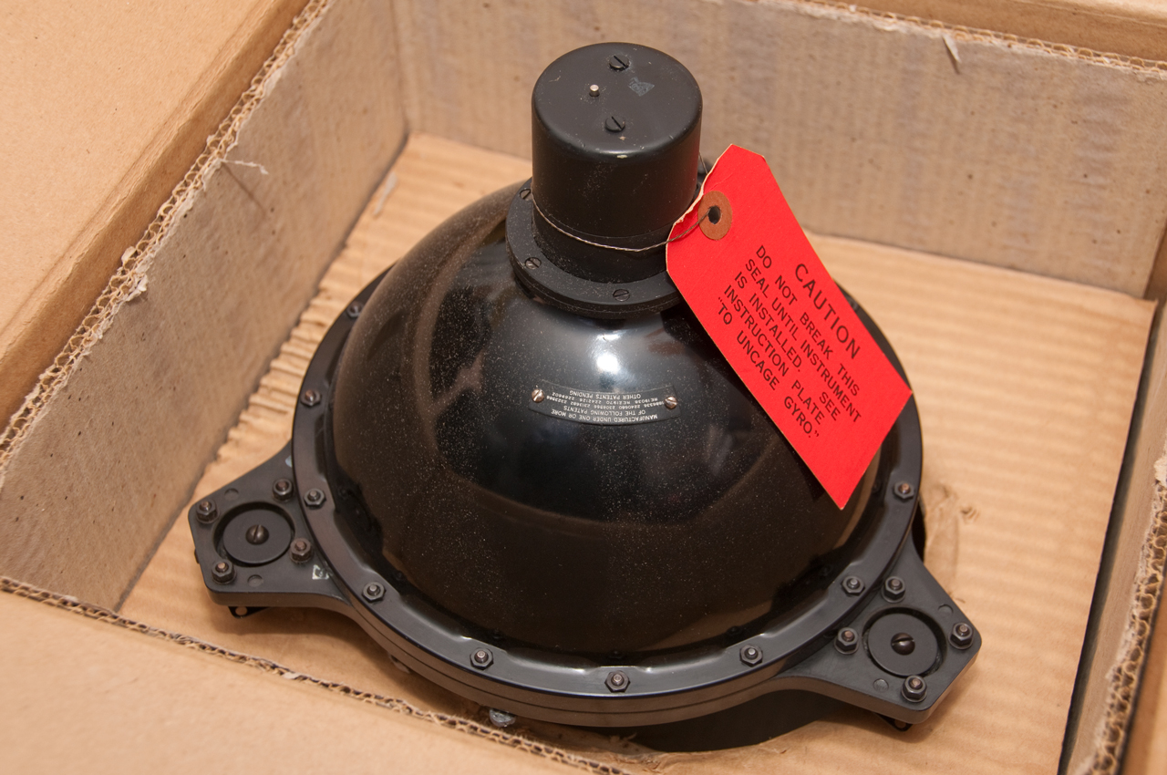
This gyro is mounted in a shock housing. There are screws on the right face and tapped holes on the opposite face. Not sure if it mounts like photographed with the central axis vertical or with it horizontal. The housing appears to be spot welded together, so it's not clear how to remove the gyro from the housing. Maybe by removing all the shock mounts.
Cageable Free Gyro
Manufactured by
Electronic Specialty Co. (also made the Mk 46 Torpedo Dwg NF6010A Gyro)
Portland, Oregon, U.S.A.
Model No. N4100 AA
Serial No. 4
Patents by Electronic Specialty Co.
2837652 Solid state inverters, Nailen James C, Electronic Specialty Co, Jun 3, 1958, 331/107.00R, 363/123, 327/171
3439550 Mechanical movement apparatus, Merrill Keith Goulding, Electronic Specialty Co, Apr 22, 1969, 74/424.74, 343/765 - test stand
3508447 Gyroscope apparatus (See above under torpedo gyro)
3587330 Vertical reference system, Deer James W, Electronic Specialty Co, Jun 28, 1971, 74/5.60R, 74/5.8, 73/504.18 - strap down accelerometers
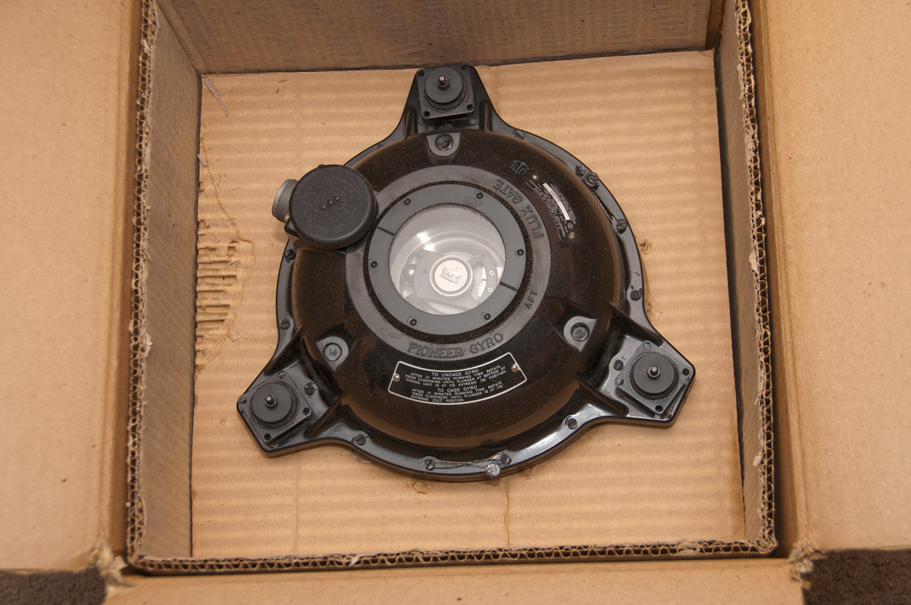
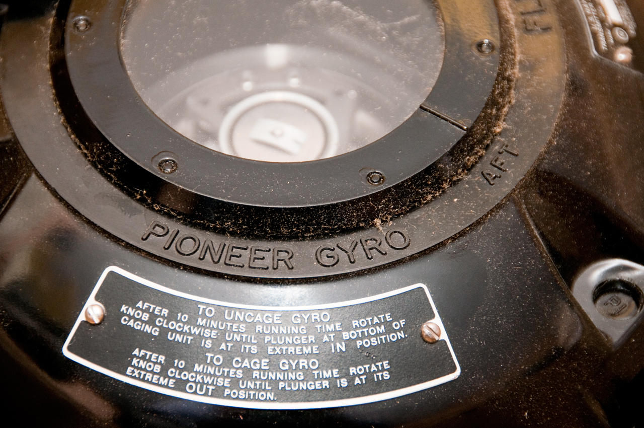
It's my understanding (Ref 15) that this is primarily a flux gate compass that uses a gyroscope to keep the flux gate level. It's probably not a north finding gyroscope system. See Aircraft Ref 48: Gyro-Stabalized Flux Gate Compass
2313682
Paragraphs below are for the Gyro compass unit AN5751 and the AN5752 master indicator.
Other parts of the system I don't have are:
AN5753 Amplifier
AN5754 Electrical caging attachment for the gyro
AN5755 Remote manual caging control
AN5756 Remote electrical caging control
AN5730 Remote magnetic compass indicatorCompass system, Stuart Jr Alfred A, Bendix Aviat Corp, filed: Nov 5, 1940, pub: Mar 9, 1943,
33/361, 340/870.33, 336/120, 318/653, 324/247, 310/266, 336/123, 336/178, 310/49.47
uses both 400 Hz and 800 Hz power
2361433 Magnetic compass, Stuart Jr Alfred A, Bendix Aviat Corp, filed: Oct 31, 1942, pub: Oct 31, 1944
33/319, 324/247, 318/654, 318/647, 33/361, 340/870.33
gyro stabilized sensor - permalloy (Wiki) & Mumetal (Wiki) mentioned
Fig 3 shows the stabilization gyro (not a north finding gyro)
2240680 Earth inductor compass, Stuart Jr Alfred A, Bendix Aviat Corp, filed: Dec 29, 1938, pub: May 6, 1941
33/362, 318/747, 318/647, 324/76.81, 340/870.34, 324/86
motor driven sensor
RE22699 Magnetic compass, Alfred A. Stuart, filed: May 21, 1940, pub: Nov 27, 1945,
Reissue of 2240680 with gyro stabilization.
33/319, 340/870.33, 33/361, 318/654, 318/647
2446939 Frequency doubling transformer, Maccallum Alan M, Bendix Aviat Corp, filed: Sep 16, 1944, pub: Aug 10, 1948
324/253, 340/870.26, 363/172, 33/361, 324/254, 340/870.33
using (800 Hz) the second harmonic of the common 400 Hz aircraft power frequency results in better flux gate operation.
2554246 Magnetic pickup device, Emerson John F, Bendix Aviat Corp, filed: Oct 31, 1944, pub: May 22, 1951
324/253, 33/361, 324/247, 340/870.33, 318/647
---------------------------------------
The above system is a gyro stabilized flux gate system - the below patents for for a north finding gyro combined flux gate system -----------------
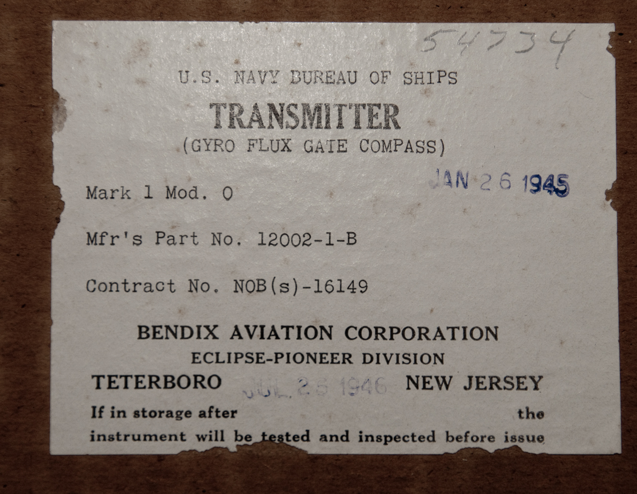
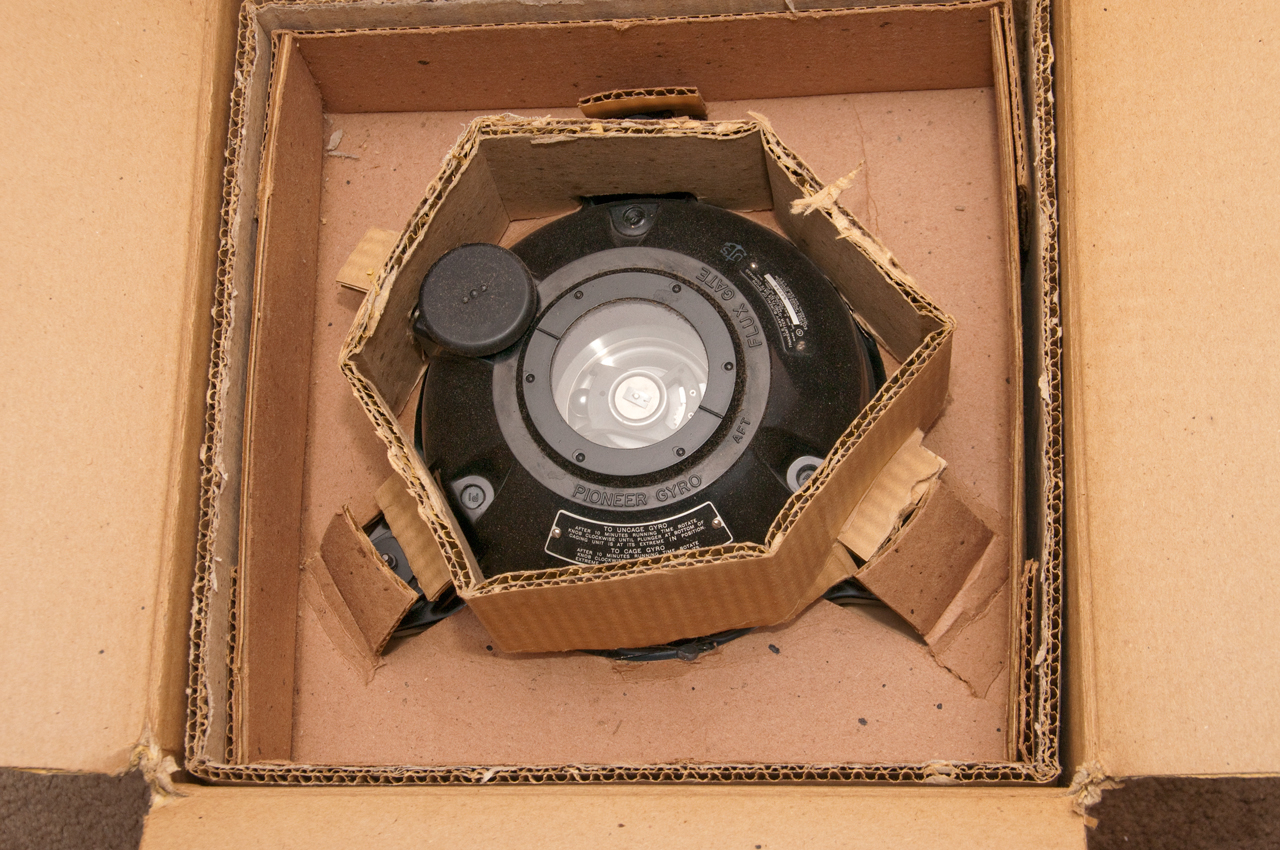
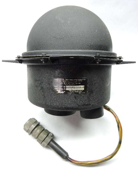
Bendix AN5751 Gyro Flux Gate Compass Mk 1 Mod 0 p/n 12002-1-B
This is a new in the box unit from W.W.II. 3-phase flux gate.
This may have NSN: 6605-00-224-2708
There also is:
YouTube - Bendix Gyro Compass Transmitter Navy AN 5751 Flux Gate
- a Bendix 12008-1-A gyro flux gate compass transmitter.
- a Bendix Master Indicator Gyro Flux Gate Compass, p/n: 12001-1A-A1 - that may go with this transmitter.
Possible reference: NavAer 08-1-507 (AAF Radio)
Once used on B17, B24 and B29 aircraft too.
Ran on 400Hz 120 volts AN 5751 here is the gyro Transmitter. AN 5752 is the Indicator
Re the web:
AN5751-1 Characteristics
Electrical connection cable watertight gland Not furnished
Electrical connection controlling agency Ana
Electrical connection identifying number Part no. an3102-16s-1p
Electrical connection quantity 1
Connector mating method External
Connector prong quantity 7
Direction sensing element type Fluxgate
Gyro current type Ac
Gyro frequency in hertz 400.0 nominal
Gyro voltage in volts 115.0 nominal
Heeling correctors Not provided
Overall height 9.344 inches nominal
Overall length 9.875 inches nominal
Overall width 10.500 inches nominal
Mounting method Stud
Quadrantal spheres Not included
Shock mount Provided
Stabilizing feature Included
Transmitting coil frequency in hertz 487.5 nominal
Transmitting coil voltage in volts 2.5 nominal
Fig 0
Fig 1
Fig 2
Fig 3
Fig 4
Fig 5
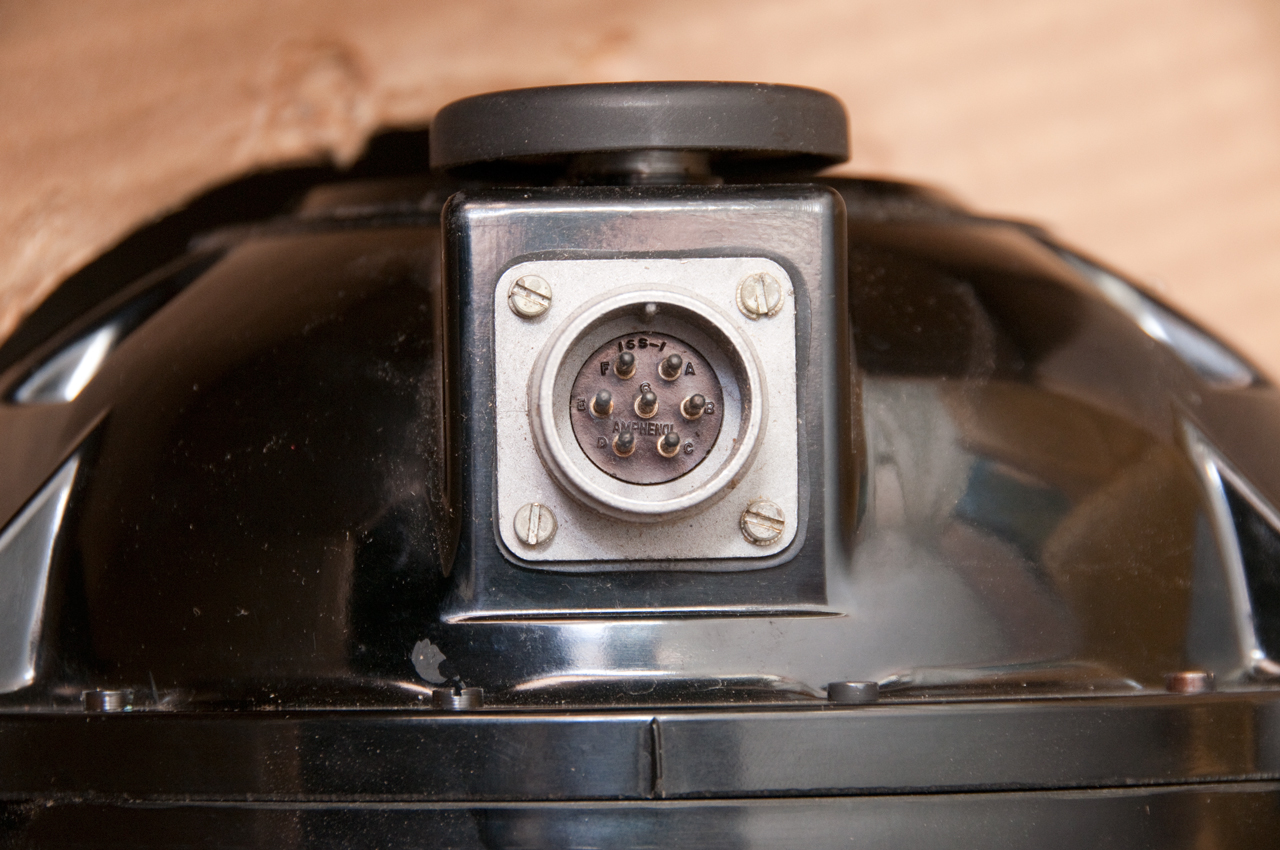
Fig 6 Amphenol 16S-1 maybe 1"-18 thread
7 male pins marked A to F.
I've read that 115 VAC 400 Hz 1-phase is applied
to the pins at 1:00 and 3:00 (blk & yel wires).
There are phasing capacitors for the other two phases.
Fig 7 cable connector:
Amphenol blue core:AN-3057 16S-1SF
cable clamp:
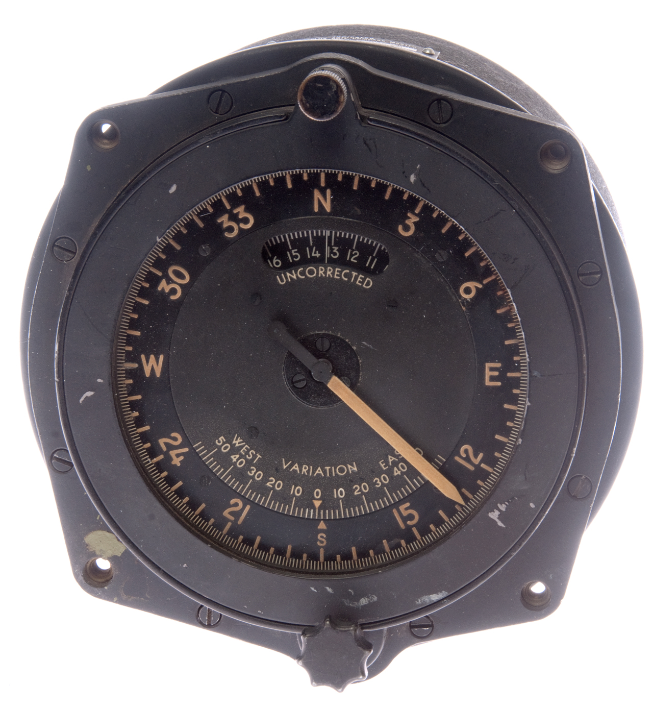
Bendix AN5752-1 Gyro Flux Gate Compass Master Indicator
This is the master indicator part of the Gyro Flux Gate Compass System. It gets it's input from the AN5753 flux gate amplifier on one connector and has another connector that outputs a signal for the AN5730 remote compass indicators.
AN5752 Fig 1 Front
Bottom knob for adjusting the local variation
between true north and magnetic north.
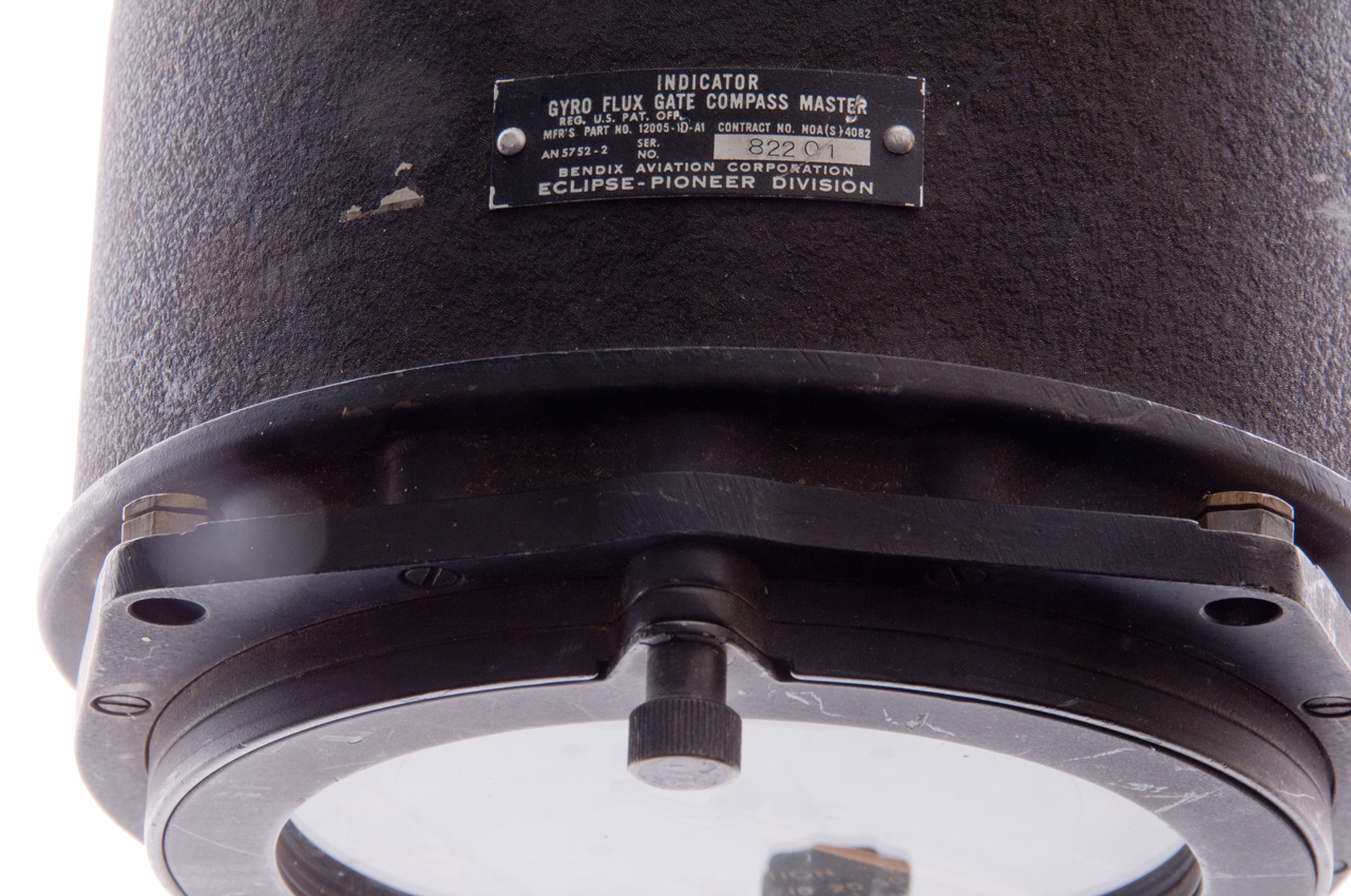
AN5752 Fig 2 Label
Indicator
Gyro Flux Gate Compass Master
Reg. U.S. Pat. Off.
Mfr's Part No. 12005-1D-A1 Contract No. NOA(S)4082
AN5752-2 Ser. 82201
Bendix Aviation Corporation
Eclipse-Pioneer Division
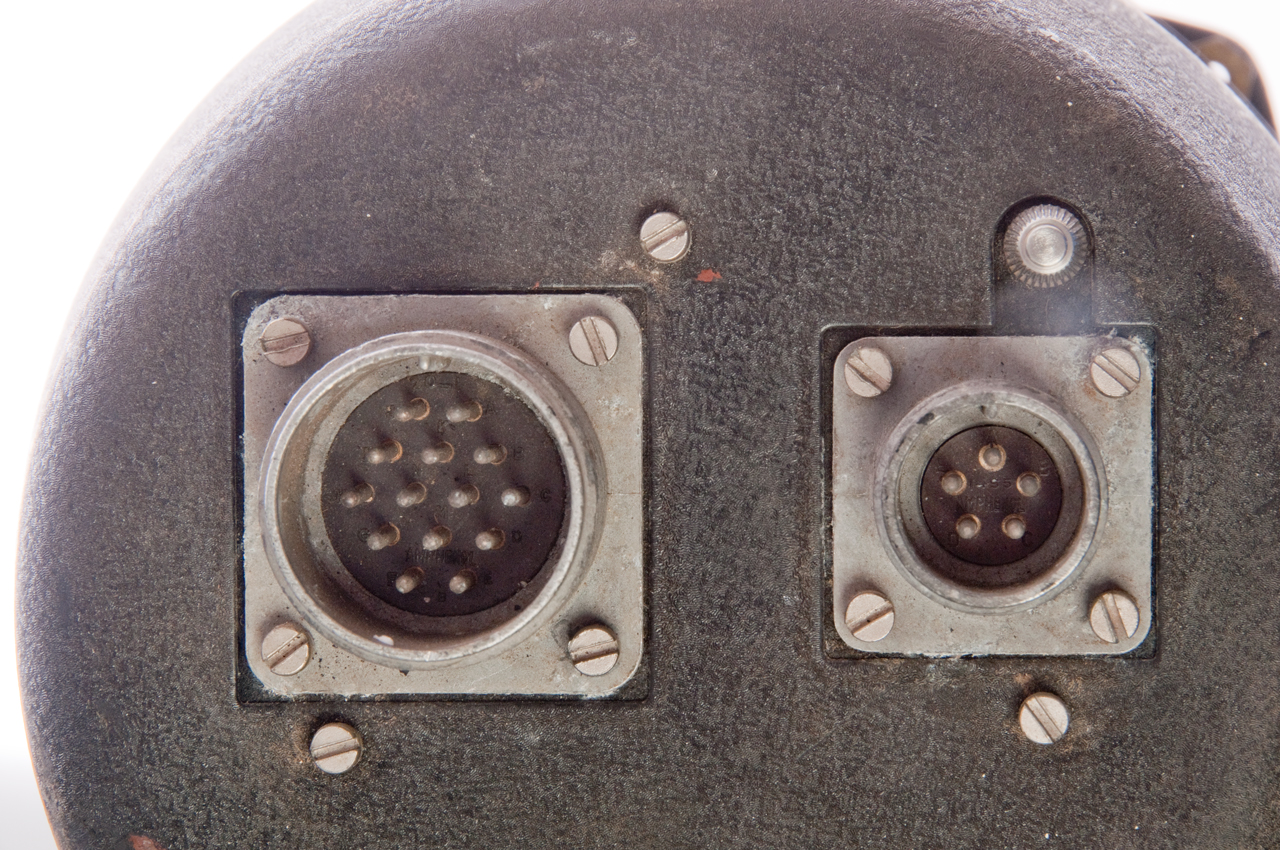
AN5752 Fig 3 large connector from amplifier
small connector to remote compass indicators
Small knob above small connector for correcting for
any difference between the flux gate north and the
aircraft centerline.
AN5752 Fig 4 Top pin removed and ring removed
exposing the 24 hard iron correction adjustments.
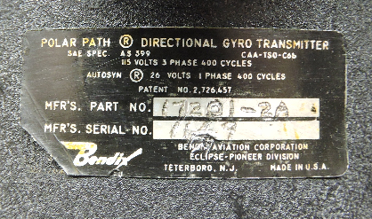
Polar Path Fig 1
Polar Path Fig 2
Patent 2726457 Compass system
This system allows the gyro to wander rather than the prior art method of using a flux gate compass to force the gyro to it's reference position.
What aircraft used this system? let me know
2726457 Compass system, Gerhardt W Boehm, Konet Henry, Charles E Hurlburt, Bendix Aviat Corp, Dec 13, 1955
33/319, 33/317.00D, 318/489, 318/647
calls: 2346849 Compass control indicator system, Lear William P, Lear Avia Inc, Apr 18, 1944, 33/317.00R - both north finding & magnetic
This is the Bendix Polar Path system.
2614335 Navigation system, Paul A. Noxon, Bentlix Aviation Corporation, filed: Nov 22, 1948, pub: Oct 21, 1952, 33/317.00R, 324/247
----- patent application: 516,488, filed December 31, 1943 a massive application !-----
2589834 Automatic steering system, Alan M Maccallum, Bendix Aviat Corp, filed: Jan 31, 1946, pub: Mar 18, 1952, 318/591, 244/197, 318/580, 244/179
2432036 Automatic control system
2471637 Automatic steering control
2474618 Altitude control
2487697 Control system
2516641 Automatic pilot control
2512902 Aircraft altitude control
2552196 Altitude control
2575890 Automatic approach control system
2585164 Radio navigation system - linked to RDF
2592173 Automatic control of mobile craft
2593014 Altitude control system
2594326 Trim tab servomotor control
2614335 Navigation system
2614776 Flight controller for automatic pilot
2620148 Radio-operated controller for all electric automatic pilots
2625348 Automatic pilot
2636698 Automatic steering system
2642554 Automatic steering system
2662207 Automatic steering system with displacement limiting means
2663519 Engagement station for automatic pilots
2674423 Automatic pilot, Noxon Paul A, Bendix Aviat Corp, filed: Dec 31, 1943, pub: Apr 6, 1954, 244/197, 318/591, 267/1502673314
2680580 Altitude control switch
2691122 Positioning system monitor
2733879 Trim Tab Servo Motor Control
2736517 Turn controller for automatic pilot systems
2745614 Aircraft control system
2754501 Altitude control
2765435 Maximum deflection limiter for the control surfaces of a mobile vehicle
2769132 Noise eliminator for automatic pilot systems
2772059 Automatic pilot
2838258 Automatic pilot
2859005 Monitoring system for aircraft auto pilots
2884582Automatic pilot servo system
While watching the movie "First Step" I discovered the Box Sextant. Which was used to train astronauts to find the stars that needed to be sighted as inputs to the AGC. A gyroscope stabilized platform type Inertial Measurement Unit (IMU) was also connected to the AGC. You can see it in action in this YouTube video: CuriousMarc Inertial Gyroscope Spin Up and Demo - Links to Ed Thelen Gyro page -
Most, if not all, of the gyroscopes require an AC power source with a frequency of 400 Hz (the standard aircraft AC supply frequency (Wiki).
Some gyroscopes only need single phase AC and others require 3-phase (Wiki) AC.
A notable exception is the Norden Bomb Sight (Wiki, Twin Beach) that runs directly on 28 VDC. This can be a problem because of carbon dust in the bearings from the motor brushes.
Definitions
An inverter (Wiki: Power Inverter) changes DC voltage into AC voltage.
A rotary inverter (Wiki: rotary converter, motor generator) is a mechanical rotating machine type inverter.
Early car radios used a vibrator power supply (Wiki: electronic vibrator) to convert the car's 6 Volt electricity into high voltage AC that was rectified to power the vacuum tubes.
A static inverter is an inverter where there is no mechanical motion.
Induction motors (Wiki) use no slip rings or commutators and so are an ideal type of motor for a gyroscope flywheel. Some early gyroscopes used DC motors but as the carbon dust from brush wear got into the bearings and that causes problems. I'm using DC motor driven flywheels to make a lab demonstration gyroscope because they don't need to have the reliability of a navigation type gyroscope
Bendix E-1617-1 Inverter
This is a classical W.W.II vintage rotary inverter, but they didn't have solid state static inverters then so just called it an inverter. It arrived DOA with the armature rusted to the filed laminations.
This may have been used in aircraft to convert the 28 VDC mains power to 115 VAC 400 Hz 3-phase power to operate gyroscopes and Synchro (Wiki) systems like the early Flux Gate (patents) compass. My hope is that it can be restored to power gyroscopes.
Functional Description Fig 6
At the DC end (Fig 3) there are a couple of slip rings, one connected to the motor shunt field and the other to ground. There's a 40 Ohm resistor across them as well as the governor contacts on the face of the fan (Fig 7). The other end of the motor field goes through a filter choke then to pin D. The armature uses 4 brushes, two opposite brushes are connected to ground and the other two are in series with the motor series field which goes to the same choke terminal as the shunt field. When the shaft speed is too high the governor contacts on the face of the fan open inserting 40 Ohms in series with the DC motor shunt filed winding lowering the current and thus slowing down the armature.
At the AC end (Fig 4) the three slip rings are connected to the ends of a "Y" would armature with the center floating. Phase 3 is grounded and the other two phases are brought out on the connector pins A and C. The AC field coil is connected to the same choke pin as the two DC field coils. The other end of the AC field coil is connected to the patented carbon pile Voltage Regulator to ground. The electromagnet that drives the voltage regulator is fed from the output of a full wave Selenium bridge rectifier (Wiki). The input to the full wave bridge comes from AC phase 1 and the series connection of a 1,250 Ohm resistor and a 500 Ohm variable resistor to ground whose screw voltage adjustment is adjacent to the connector. When the AC output voltage is too high the current through the voltage regulator increases causing it's resistance to increase thus lowering the AC filed current thereby reducing the output AC voltage (regulated to 115 VAC).
Connector
1-1/4" - 18 thread, 4 male pins (A to D), blue plastic core marked Amphenol 4-257, 20-4PF
Pin
Function
A
AC Phase 1
B
DC Ground & AC Phase 3
C
AC Phase 2
D
27.5 VDC Input
To open the control box use a 7/16" wrench to loosen the nut on the top (Fig 7).
The label reads:
Inverter
B.A.. Part No. E-1617-1
Contract No. NOAS 52-S27 F
Stock No. R17-I-7427 Mfr's Dwg. No. 12142-1-A
Mfr's Serial No. RB-24683 A
Input 27.5 Volts D.C. 22 Amps. D.C.
Output 3 Phase 115 Volts 400 Cycles
250 Volt Amperes 1.0 Power Factor
Bendix Aviation Corporation
Eclipse-Pioneer Division
Voltage Regulator
Type: 1067 Model: 17
Serial: RB-450010
Style: 4 Volt: 115
Bendix Aviation Corporation
Eclipse-Pioneer Division, Teterbro, N.J.
Made in the U.S. under one or more of the following patents:
2332140 Electromagnetic apparatus, Finnegan Martin J, Bendix Aviat Corp, Oct 19, 1943, 338/105, 338/106 - Carbon pile - electromagnet and spring
2474732 Automatic control system for dynamoelectric machines, William F Fell, Evan S Smith, Bendix Aviat Corp,
filed: Aug 10, 1943, pub: Jun 28, 1949, 307/57, 322/24, 322/82 - motor field control
2481752 Electric regulator with diaphragm type spring, Jenny Cletus J, Pryor Thomas F, Bendix Aviat Corp, filed: May 15, 1946, 338/105, 267/158 - carbon pile
2481771 Carbon pile regulator, Greene Neild William, Bendix Aviat Corp, filed: Aug 25, 1945, 338/105, 267/158 -
2481782 Carbon pile regulator, Alexander Relchel Wladimir, filed: Sep 26, 1945, 338/105 -
D154246 Carbon pile regulator or similar article, Earle Rhea Davis, Bendix Aviation Corporation, filed: Apr 23, 1945
Fig 1
Fig 2
Fig 3 DC motor
Fig 4 AC generator
Fig 5 Inside Control Box
Fig 6 Wiring Diagram under lid
Fig 7
Fig 8 Cable connector
Bendix MS3106E20-4S
Omron 3G3EV Inverter Variable Frequency Drive (VFD)
Variable Frequency Drives (Wiki: VFD) are used to control the speed of industrial and air conditioning motors. Most of these are 3-phase induction motors (Wiki). Typically the drive frequency is in the range of a few Hz to 60 Hz, the VFD controllers typically allow frequencies up to 400 Hz.
These typically power 1 HP and larger motors. This one will run on single phase 220 VAC but most of them require 3-Phase AC input power. To power this I'm using a 115 VAC to 230 VAC step-up transformer which I'm guessing has much less than 750 Watts (1 horsepower) capacity, but that's OK since all these gyros have fractional HP motors.
Omron Fig 1 Displaying 17 Hz at power up.
Bendix Aircraft Static Inverter Type 1964771-3
Label
Inverter Type No.1964771-3
24 VDC TSO-C4c AS-396B
Wt Lbs: 1.41 Ser No.
The Bendix Corp Navigation & Control Div
Terterboro, New Jersy Made in U.S.A.
Photos
Static Fig 1
Static Fig 2
Static Fig 3
Static Fig 4 Cable Connector
Amphenol PT06A-10-6S(SR)
The only IC on the PCB is a 54L72N dual flip-flop and there are many parts on the PCB in pairs.
There are 3 power transistors, one on the heat sink and 2 on the PCB. Since there are two output frequencies I'm guessing that that pair on the PCB are for one of the frequencies and the single one on the heat sink is for the other frequency.
This is a single phase 400 Hz inverter. Maybe with a square or modified sine wave (Wiki) output.
Connector
The 3-lug connector has a core marked
shell: PT02E-10-6P
core: 10-6
Table measured connecting input to internal red and black wires.
At +20 VDC input the output stabilizes voltage with no load. As the input voltage is lowered the output lowers.
Pin
Function
A
nc
B
129 VAC @ 370 Hz out
C
12 VAC @1040 Hz out
D
+24VDC (<0.5A no load) in
E
Ground
F
18 VAC @ 1110 Hz
Output between B and E is 92 ACV, 50% duty cycle, 370 Hz.
Reverse Engineering
Connector Resistance between pins
A
B
C
D
E
F
A
-
OL
OL
OL
OL
OL
B
-
19
OL
OL
19
C
-
OL
OL
1
D
-
1M
OL
E
-
OL
F
-
Connector Wiring
Pin
Conn wire color
terminal
Coil
PCB
A
nc
B
yellow
Coil
C
blue
Coil
D
red
PCB 1
E
black
PCB 4
F
violet
E1 & E2
Coil
brown
white
Coil
PCB 7
Xistor
red
Coil
PCB 5
orange
Coil
PCB 2
green
PCB 6
Xistor
Note: If the 24 VDC input connection is made to the Agilent E3617A power supply (max 1 Amp output) and then the power supply is turned on, the inverter does not start. But if the power supply is turned on and then the connection is made to the inverter it starts. The starting current is probably greater than an amp so after the power supply charges it's output capacitor it can deliver a spick of current that's enough to get the inverter started. You can hear a faint whine when the inverter is running.
Tested: +24 VDC input on pin D with ground return on pin E. With no load draws 0.487 Amps.
Pin B = 129 VAC @ 370 Hz
Pin C = 12 VAC @1040 Hz
Pin F = 18 VAC @ 1110 Hz
Brushless DC Motor Controller
This is just an idea since BLDC controllers (Wiki) typically use a 3-phase AC drive.
Static 3-Phase Inverter
This may the the best solution. It's small and solid state plus designed to aircraft use.
Input: 28 VDC
Output rated at 115 VAC, 400 Hz, 17 VA which should be enough for most small 3-phase gyros.
Fig 1
Fig 2 What does "LTG. to INDIC." mean let me know
SP8030 Digital Phase Indicator

When wiring 3-phase power to a motor there are two connections, one results in clockwise rotation and the other connection in counterclockwise rotation.
This device will tell you what wiring connection you have. This may be important for north finding gyroscopes as it would reverse North and South.
2A6A1 AM-3349 RF Amp Inverter
Fair Radio had this in their June 2024 sale.
DC-AC 400 HZ INVERTER from AM-3349.
Input 26 VDC
Designed outputs 120 VPP 400 hz and 156 VPP 400 hz. Also 12.6 VPP 400 hz 600 ma for filaments.
Components mounted in irregularly shaped casting. Transformer is not removable. Removed from equipment. With schematic. 2.3×6.6×4.9 5 lbs sh.
This is an army inertial navigation based on a spinning mass gyroscope designed to locate the user withing about 10 meters anywhere on Earth. Note in addition to the Lat & Lon output there is also a very accurate azimuth determining system (North Finding).
Manuals:
TM 5-6675-308-34
TM-5-6675-308-12
TM-5-6675-308-12-HR
TM-5-6675-308-24P
NSN: 6675-01-071-5552
Wanted
Any Kenyon Gyroscope to Open Up or Already
Opened.Instructions on how to open.
The basic unit is a cylinder that holds two gyroscopes with their spin axis at right angles to each other.
See patent 3006197 below.
Details on the versions at: Kenyon Gyro Repair Info.
Kenyon Drawings & Technical Information -
Serial Number: (2 digit year) (2 digit month) (1 letter: Model) (2 digit serial No.)
YouTube:Video Stabilization for High Speed Auto Chases and Vehicle Commercials, 2:26 - KS-6
Letter
Model
A
KS-2
B
KS-4
C
KS-6
D
KS-8
K
Inverter
T
Charger
W
KS-10
Z
KS-12
Size Table
Does the dash number after KS-nn equal the max load weight in pounds?
How Do You Choose Which Kenyon Gyro Will Work For You? -
For each flywheel size there are two metal options: Brass and Tungsten. The Tungsten option has a higher weight and moment of inertia so works with a higher load.
The below table applies to the cylinder shape gyros (Kenyon 2-lobe), not the "X" shape units (Kenyon 4-lobe) or 6-lobe units.
Model
Material
Weight
#
Cylinder dia.
Max Load
#
Starting
Amps
Run
Amps
KS-2 Brass
1.8
2-13/16"2
1.2
0.8
KS-4 Tung
2.4
4-6
KS-6 Brass 3.6
3-13/32"8
2.6
1.6
KS-8 Tung 5.5
7 - 12
KS-10 Brass
?
4-3/4" ?
?
?
KS-12 Tung ?
4-3/4"
?
?
?
There is a very substantial difference in not only size, but also in the torque.
The Nikon D300s body only weighs 30 oz (1-7/8 lbs). With the 18-200mm lens it totals 3# 6oz (3-3/8#).
the 9x63 binoculars weigh 2# 5 oz (2-5/16#).
Gyro Versions
GyroMounts combines the Kenyon gyroscopes with gimbals.
Obsolete
Ver 1
Ver 2
Ver 3
Ver 4
1959 - 1999
<2005
2005 - 2008
2008 - 2012
>2012
Inverter Versions
Ver 1
Ver 2
Ver 3
Ver 4
DC Input
Cinch Jones (Bottom)
Wide blade: +12
Lemo (right)
red dot (slot): +12
XLR-Neutrik
Pin 1: -12
Pin 4: +12
XLR-Amphenol
Pin 1: -12
Pin 4: +12
AC Output
Cinch Jones (Top) Lemo (Left)
Patents
Mostly Theodore W. Kenyon patents.
1324478 Damping Means for Gyroscopic Pendulums, Harry L. Tanner, Sperry Gyroscope Co, 1919-12-09, - "This invention relates to gyroscopes adapted to be used for stabilizing purposes on aeroplanes or other moving vehicles," uses springs to hold gimbal just like Kenyon.
1955502 Boat speedometer, Theodore W Kenyon, Kenyon Instrument Corp, 1934-04-17, -
2307590 Means for indicating turning movements of a craft, Theodore W Kenyon, Sperry Gyroscope, 1943-01-05, - 2-phase AC powered gyros
2218929 Deviometer, Theodore W Kenyon, Sperry Gyroscope, 1940-10-22, - combines directional gyroscope & gyroscopic. horizon for pitch. - not used?
2291635 Means for indicating turning movements of a craft, Theodore W Kenyon, Sperry Gyroscope, 1942-08-04, - air powered gyro, see: Turn & Slip Indicator
2373120 Erection device for gyro verticals, Theodore W Kenyon, Sperry Gyroscope, App: 1941-06-19, Top Secret, Pub: 1945-04-10, -
2373315 Automatic pilot for aircraft, Theodore W Kenyon, Sperry Gyroscope, App: 1940-05-22, Top Secret, Pub: 1945-04-10, -
2475746 Radar antenna stabilizer, Theodore W Kenyon, Kenyon Gyro & Electronics, App: 1947-01-25, 318/5; 89/41.07; 318/8; 318/489; 343/765; 343/882; 74/5.22; 89/41.09; 318/14; 318/649; 343/766 -
2489294 Flight attitude indicating instrument, Theodore W Kenyon, Kenyon Gyro & Electronics, App: 1947-06-21, 33/328; 33/351 -
2499391 Erector mechanism for gyroscopes, Theodore W Kenyon, Kenyon Gyro & Electronics, App: 1948-03-02, 74/5.44 -
2570130 Gyrostabilized sighting instrument, Theodore W Kenyon, Kenyon Gyro & Electronics, 1951-10-02, 74/5.22; 33/275G; 33/268; 352/244 -
Fig 1 & Fig 2: Binoculars -
Fig 3 & Fig 4: Dual Gyroscope
Fig 5, Fig 6 & Fig 8: Sextant - I doubt this was used since averaging aircraft sextants were introduced.
Fig 7: Camera
2811042 Stabilizer for sighting devices, Theodore W Kenyon, Kenyon Labs, 1957-10-29, 74/5.22; 359/554 -
3006197 Stabilizing instrument, Theodore W Kenyon, Ernest H Pallme, Kenyon Labs, 1961-10-31, 74/5.22; 74/5R; 359/556; 359/557 -
20060070646 System for improving the balance of a person, Ronald Denman, Kenyon Labs, App: 2004-10-05, -
20160102945 Gyroscopically assisted weapon stabilization systems, Arnold Itzkowitz, Ronald J. Denman, App: 2013-12-19, - requires special spring mount for Barrett 50
D682717 Gyroscope housing, Ronald Denman, Peter Papathanasiou, Kenyon Labs, App: 2012-05-21, D10/66 - 6 gyros for 3-axis stabalization
KS-4 Camera Stabilizer
Jan 2023 - Got this "for parts or repair" on eBay from a high volume seller. The best case is the seller did not know how to test it and it's fully functional, or something is wrong. TBD.
The KS-4x4 functionally is two KS-4 units mounted at 90 degrees.
YouTube: Production in Under 5 Minutes: Kenyon Labs KS-4x4 Gyro, 2:15 -
KS-4
Kit
KS-6
Kit
Gyro
KS-4 Gyro Stabalizer
s/n 0703B25n.a.
Inverter
KP-4 Inverter
s/n 0703K09KP-6 12V Inverter
s/n 1001L75Charger
KBC 6 Hr Charger
s/n C806T27KBC-400327 Charger Cables
TBD
TBD
Carry
Bag
Yes
Yes
Battery
n.a.
n.a.
It looks like there were two gyros kits, but he KS-6 gyro is not included.
The 24V input inverters that are for the KS-10 and larger gyros may be made by SEC America for the KS-(big).
Gyro
The pad for the attachment has four 4-40 Tapped holes x 0.32" deep in a rectangle that's 13/16" x 7/16". The photos I've see show the adapter plat extending along the long axis of the gyro with a 1/4-20 male nut that has a T-bar handle.
When first started the inverter draws 1.26 Amps at 13.35 VDC.
Fig 1
Fig 2
Four tapped holes for adapter plate
for 1/4-20 camera male tread.
After running for some time it's down to 0.85 Amps.
Inverter & Battery Carry Bag
I think the bag is to hold the battery. The inverter connects to the top of the bag with Velcro (Wiki).
The bag may hold the Bioenno Power BLF-1209 (BLF-1209WS_User_Manual_rev_04_23_2019.pdf) (14.6 VDC at full charge) which is a Li-FePo4 replacement of a 7AH lead Acid GellCell, which may have been the battery that was used with the KS-nn series of gyros?
There are 4 versions of the inverter. This is Version 3.
4 pin XLR connector is the12 VDC input.
Pin
Function
1
-12VDC
4
+12VDC
2 & 3
nc
Torrid Transformer
Red and Green wire ends total 9. Same as Royer Inverter.
If Royer then uses core that saturates, i.e. square B-H Curve.
Term
Wire
2/3
Red & Green
4
Red
AC
stranded Green
1
Green
7
Red
5
Green
6
Green
8
Red
2N4922 (2N4921_D-1801432.pdf) - NPN, 1 Amp continuous, 3 Amp peak, Vcesat< 0.6V4922
Fig 1
Fig 2
Fig 3
Fig 4
Input: 13.35 VDC
Output: 114 VAC @ 449.9 Hz
KP-4 Lead Acid Battery Charger
Fig 1
Fig 2
Battery
Eight or nine amp hour lead acid or 11 amp hour Li-FePo4 batteries are available from Kenyon.
KS-6 Camera Stabilizer
Not part of first eBay package.
Fig 1
Fig 2
Applied 13.8 VDC to KP-6 inverter at 1:18 and drawing 2.34 Amps. When it is starting you need to put it to your ear to hear the motors running because they are very quiet.
The Kenyon data shows starting current of 2.6 Amps and run current of 1.6 Amps.
This KS-6 is drawing about the factory values.
Plot Amps v. Minutes (13.8 VDC input to KP-6 inverter)
KP-6 Inverter & Battery Bag
Fig 1
KBC 6 hour Lead Acid Battery Charger
This is a general purpose lead acid charger, not specific to the KS-6 size.
Fig 1
1/4"-20 Tripod Thread
Both the KS-4 and KS-6 came without the tripod threads. I expect they were mounted on a camera rig so the 1/4"-20 hardware was removed. I got the wheel type 1/4-20 for the KS-4 and a "tommy bar" for the KS-6. Note: both of these are also available in the European standard 3/8"-16 thread.
KS-8 Camera Stabilizer
The KS-8 is the same physically as the KS-6. The difference is the KS-6 has brass flywheels and the KS-8 has tungsten.
The density of brass is 8.4 to 8.73 g/cm3 (Wiki) whereas Tungsten has a density of 19.3 g/cm3 (Wiki).
The moment of inertia is directly proportional to the mass of the flywheel so the KS-8 will have a little more than twice the restoring force as the KS-6.
This may have come from Tyler Camera Systems (web page). Their minigyro contains a pair of KS-8 units, so that may be where this came from. This unit has a Lemo connector on the gyro cable, not the Kenyon standard DIN type connector. The power supply was custom built based on an aircraft Static Inverter. 28 VDC input to the inverter is on an XLR plug. It might be wired the same as the XLR plug used on the above Kenyon inverters or may be different since the input voltage is 28 VDC rather than 12 VDC? Included was an XLR extension cable.
Fig 1
Kenyon Gyroscope related vendors
Gyromounts.com: YouTube -
Chapman/Leonard Studio Equipment Inc. -
There are a couple of meanings: Flywheel or including Gimbals. In order to do the Foucault demonstration of the Earth's rotation it's necessary that no only the flywheel, but also the gimbals are well balanced.
2243458 Apparatus for balancing rotors, Orland E Esval, Carl A Frische, SPERRY GYROSCOPE CO Inc, 1941-05-27,G01M1/22 - flexible mounting, photocell and vibration pickups
2521141 Electronic circuit for triggering stroboscopic devices, Arthur C Allen, Stewart Warner, 1950-09-05, -
2656713 Apparatus for indicating unbalance in rotary bodies, Arthur C Allen, Stewart Warner, 1953-10-27 - wheels & tires
2702883 Vibration pickup, Arthur C Allen, Stewart Warner, 1955-02-22, -
2737813 Apparatus for indicating the characteristics of unbalance in rotatable masses, Arthur C Allen, Stewart Warner, 1956-03-13, -
2782641 Balancing apparatus, Arthur C Allen, Stewart Warner, 1957-02-26, - Wheel + Tire balancer
2697343 Dynamic calibrator for rate gyroscopes, Walter J Hirtrciter, Air Force, 1954-12-21,
G01C25/005 - expansion of heated wire torques gyro platform under test without vibrations
2983148 Apparatus for use in the dynamic balancing of rotors, White John Maurice Forbes, De Havilland Aircraft Co Ltd, 1961-05-09,G01M1/22 - includes gyro rotors, drilling in 2 places in rotor rim,
Cites:
1612329 Indicating Device for Small Balancing Machines, W.E. Trumpler, Westinghouse, Dec 28, 1926, - springs support flexible base, dynamo-electric machines
1695904 Balancing Machine, C.R. Soderberg, Westinghouse, Dec 18, 1928, - math analysis, two planes
2043458 Sewage?
2381645 Apparatus for Determining Unbalance in Rotors, O.W. Carlstein, Aug 7, 1945, - flexible base, up to 40,000 RPM, gyroscope, drill one or more holes in rim.
2420765 Dynamic Balancer, R.B. Annis, May 20, 1947, - motor or generator armatures
2521141 Electronic Circuit for Triggering Stroboscopic Devices, A.C. Allen, Sep 5, 1950, wheel balancing (related to timing light?)
2622437 Rotor Balancing Machine, K.F. Frank, Sperry Corp, Dec 23, 1952, - air driven gyro rotors, flexible mount, photocell, vibration sensors
Cites:
1210085 Method and Means for Balancing Rotating Dodies, M. LeBlanc, Dec 26, 1916 - flexible mount for flywheels?
1263325 Fluid Driven Motor, E. Klahn, Apr 16, 1918, for smoothly driving a gyroscope
1600569 Method and Means for Balancing Masses, E.A. Sperry, Sep 21, 1926, flexible mount for large turbines and gyros (ship stabilizer?)
2140398 balancing and Center Locating Machine, N.R. Buckingham, Dec 13, 1938, - crankshaft
2243457 Method and Apparatus for Balancing Rotors, O.E. Esval et al, May 27, 1941 - air driven gyro rotor
2243458 Apparatus for Balancing Rotors, O.E. Esval, et al, May 27, 1941, -
2289074 Balancing Machine, F.C. Rushing et al, Westinghouse, July 7, 1942, - spring mount, 2 planes, dynamo electric machines
2293371 Balancing Machine - Crankshaft
2306625 Hydrauic Centrifuge, Hepworth Co, sugar processing
2382673 Balancing Machine, K.E. Sihvonen et al, GM, Aug 14, 1945 - air driven gyro rotor, flexible mount
2382843 Electronic Type Balancer, R.B. Annis, Aug 14, 1945, - armatures
2383588 Balancing Machine, S. Bousky, Aug 28, 1945, 73/466; 73/473; D10/82, G01M 1/22 - air driven gyro rotor
2405474 Balancing Machine, T.C. Van Degrift, GM, Aug 6, 1946, - shaft driven gyro rotor
2405430 Apparatus for Analuyzing Rotational Unbalances, E.L. Kent, Aug 6, 1946, - air driven gyro rotor
2487035 balance Testing Appliance, I.A. Weaver et al, Nov 1, 1949,
Cites:
1704341 Balancing Machine, T.C. Rathbone, Westinghouse, Mar 5, 1929, - trial and error adding weights
2092096 Amplifier Circuit, L.E. Swedlund, Westinghouse, Sep 7, 1937, - for use with stroboscope
2131602 Dynamically Balancing Rotatable Body, E.L. Thearle, GE, Sep 27, 1938 - armatures
2293371 Balancing Machine, T.C. Van Degrift, Aug 18, 1942, - Crankshafts
2301291 Apparatus for Balancing Rotating Parts of Machines, N.V. Kolesnik, USSR, Nov 10, 1942 - for balancing machines in the field after wear
3363303 Weatherstrip?
2382673 see above
2382843 see above
2995934 Apparatus to measure unbalance in gyroscopes, Robert T Adams, Jack B Harvey, ITT, 1961-08-15, G01M1/22 -
3130576 Means for dynamic analysis of unbalance, Alfred J A Giers, Otfried G H Maus, 1964-04-28, G01M1/22 - Flywheel balancingCalls:
1374162 Testing-stand for gyroscopes, Meitner Elemer, Sperry Gyroscope Co Ltd, 1921-04-05, G01C25/005
Calls:3164978 Apparatus for Testing Gyroscopes, G.A. Sherman et al, Jan 12, 1965 - tests overall unti, has the feel of a theodolite where the telescope is replaced by the gyroscope.
959699 Calipers & Poising Tool
984354 Poising Calipers - used to hold watch balance wheel
2088553 Balancing Machine, T.Y. Olsen, July 27, 1937, - vibration, maybe for crankshaft?
2128673 Method and Apparatus for Balancing a Grinding Wheel, A.B. Holmstrom et at, Aub 30, 1938 - vibration
2185843 Watchmakere's Poising Tool, W.F. Fraser, Jan 2, 1940
2197808 Machine for Balancing Tires, D.A. Mason, April 23, 1940, - heavy goes down, not dynamic
2731834 Dynamic Balancing Apparatus, R.O. Fehr et al, GE, Jan 24, 1956,
Reference: 2405430 Apparatus for Analyzing Rotational Unbalances, E.L. Kent, Aug 6, 1946, 73/462; 324/76.83, G01M 1/22, air driven gyro rotor2995934 see above
Cited By:
Publication number Priority date Publication date Assignee TitleUS2596288A * 1948-10-20 1952-05-13 Bell Telephone Labor Inc High-frequency phase measuring systemUS2616288A * 1945-01-04 1952-11-04 Stewart Warner Corp Electrical apparatus for detecting unbalance in rotating bodies- flashes strobe light at point where weight is needed on tireUS2981112A * 1955-11-30 1961-04-25 Gen Motors Corp Unbalance measuring apparatusUS2985833A * 1955-11-30 1961-05-23 Gen Motors Corp Balancing apparatusUS2988918A * 1955-07-25 1961-06-20 Gen Motors Corp Balancing machineUS3041599A * 1959-08-18 1962-06-26 Control Company Inc Comp Shaft angle encodingUS3044304A * 1953-06-24 1962-07-17 M Ten Bosch Inc Rotor balancerDE976179C * 1951-02-28 1963-05-09 Schenck Gmbh Carl Balancing machine with overhung WuchtkoerperUS3143888A * 1960-05-06 1964-08-11 Plane resolversUS3228251A * 1962-11-05 1966-01-11 Gen Motors Corp Unbalance measuring systemUS3443440A * 1965-04-21 1969-05-13 Abex Corp Assembly balancer
Calls:
1374162 see above
2470773 Asymmetric scorsby and method of operation, Jr Robert Haskins, Sperry Corp, 1949-05-24,G01N19/02 -
2544851 (USPTO) Performance recording instrument for direction indicators, Thomas O Mccarthy, John L Maulbetsch, Navy, 1951-03-13, G01C19/38 -
Calls:2735191 Gyroscopic Compass Instrument, L.F. Carter, Sperry Rand, Feb 21, 1956, - inverted gimbal and torsion suspension
1432570 Theodolite, M. Roux, - maybe for PIBAL use contains photograph recording of Az & El
1839893 Photogoniometer, M.R. Pierce, Jan 5, 1932 - camera sees watch, level and degree wheel
1908947 Recording Mechanism for Power Instruments and Meters, M.G. Benjamin, May 16, 1933
2091768 Recording Apparatus
2181832 Theodolite, K. Moerbitz et al, Nov 28, 1939, PIBAL observations from a ship
2239539 Sextant, O. Schmidt et al, Carl Zeiss, April 22, 1941, adjustable star brightness
2266741 Panoramic Sextant, C.J. Crane et al, Dec 23, 1941, - aircraft use
2336081 Recording Camera, black box for vehicle
2752792 Gyroscopic apparatus
2811043 Vertical reference and acceleration apparatus, Charles R Bonnell, Honeywell Inc, 1957-10-29
Air bearings (Wiki) have some advantages over ball type bearings. They were used in "spin stands" for testing hard drive components.
3012827 Gas supported bearing, Goetz Alexander, California Institute Research Foundation (Cal Tech), 1961-12-12, -
Learned about this from a YouTube video where presenter made a much larger version based on 3D printing plastic parts and then adding 21 large bolts and nuts with a 3.5" radius to increase the momentum of the flywheel.
YouTube: Hyperspace Pirate:Tightrope-walking powered Gyroscope, 12:41 - with equations and reference to Unicycle toy.
Fig 1
Fig 2
Fig 3
Saw one of these on YouTube: Spinning a C-5 Air Force Sperry Gyroscope (115VAC 3-Ph, 400 Hz) - on Ideal Aerosmith table
1924816 Directional gyroscope for borehole testers and other uses, Jr Elmer A Sperry, Sperry Gyroscope, 1933-08-29, -
Patents:
1974220 Direction indicator, Jr Elmer A Sperry, Sperry Gyroscope, 1934-09-18, - air/vacuum powered
2052866 Pilot directing gyroscope, Bert G. Carlson, Leslle F. Carter, Sperry Gyroscope, 1936-09-01, -
2061894 Constrained directional gyroscope, Bert G Carlson, Sperry Gyroscope, 1936-11-24, -
2093417 Directional gyroscope for Aircraft, L.R. Carter, Sperry Gyroscope, 1937-09-21, - air/vacuum powered
2111388 Caging means for directional gyroscopes, Bert G Carlson, Sperry Gyroscope, 1938-03-15, -
2256475 Balanced directional gyroscopic instrument, Orland E Esval, Freitag Joseph, Sperry Gyroscope,1941-09-23, - dual rotors, each 3-phase AC powered, for temperature stability.
2682115 Gyrocompass, Leslie F Carter, Sperry Corp, 1954-06-29, - dual rotors, each 3-phase AC powered, for temperature stability.
2821791 Gyro compass, Leslie F Carter, Sperry Corp,1958-02-04, - "...gyro compass employing the so-called liquid ballistic..."
This unit would be installed with it's long axis parallel with the aircraft long axis. When supplied with vacuum the gyro would act to stabilize the sight optics against the roll of the airframe.
This is the US version of the British Mark XIV bomb sight (Wiki). The Wiki page for the Mk XIV has a very good overview of it.
There are four moveable vanes (Fig 2) surrounding the gyroscope air tight case. See patents: 1518892 & 2219295 below.
The knob allows manual caging of the gyroscope, see patent 2018735 below.
Photos
Fig 1 Labels & air intake screen
Fig 2 showing 3 of the 4 erection air control vanes.
Fig 3 Caged (will be stored this way)
Note pin at top center trapped between jaws.
Image of the Sperry T-1 bombsight; aka: British Mark XIV bombsight (Wiki), Glenn's Computer Museum,
Saw one of these on eBay where the patent numbers were readable.
Label:
Roll Stabilizing unit
T-1 Sight
Mfr's Part No. 647345
Contract No. -----
Serial No. 34669 R
Patent Label:
Sperry Gyrowcope Co. Inc. Bkluyn, N.Y.
Patent Numbers:
1405807 Damping means for gyroscopes, Harry L Tanner, Sperry Gyroscope, 1922-02-07, - applied to gyroscopic pendulum - has springs like used on Keynon camera stabilizers.
1518892 Self-damping gyropendulum, Mortimer F Bates, Sperry Gyroscope, 1924-12-09, - universally suspended pendulum whereby it may swing in all directions and directly control the damping forces or torques.
"The reaction of the air through this jet will create a torque directed from the observer, which will exert a couple about axis 8 at right angles to the axis of inclination and the proper direction to restore the axis 2 in the same vertical with the pendulum axis 34, in accordance with well known laws relating to gyroscopes. "
1651845 Gyroscopic pendulum, Elmer A Sperry, Sperry Gyroscope, 1927-12-06, - used on aircraft, air driven
1934744 Means for controlling electric motors, Rowland W Barr, Bucyrus Erie (Caterpillar Global Mining), 1933-11-14, - maybe for very large gyros, like for ship stabilization? -or- wrong patent number?
1982851 Flight indicator, Preston R Bassett, Jr Elmer A Sperry, Sperry Gyroscope, 1934-12-04, - See: Turn & Slip Indicator
2018735 Gyrovertical, Frederick C Narvesen, Mortimer F Bates, Sperry Gyroscope, 1935-10-29, - caging for turn & slip indicator
2027808 Artificial horizon for aircraft, Bert G Carlson, Sperry Gyroscope, 1936-01-14, - includes barometric indication of climb/dive
2038531 Attitude indicator for aircraft, Preston R Bassett, Jr Elmer A Sperry, Sperry Gyroscope, 1936-04-28, - turn & slip indicator
2044150 Artificial horizon, Bert G Carlson, Sperry Gyroscope, 1936-06-16, - turn & slip indicator
2044151 Artificial horizon, Jr Elmer A Sperry, Bert G Carlson, Mortimer F Bates, Sperry Gyroscope, 1936-06-16, - turn & slip indicator with 4 - 2 - 0 - 2 - 4 minutes for full circle calibrated in one minute ticks.
2078560 Artificial horizon, Bert G Carlson, Leslie F Carter, Sperry Gyroscope, 1937-04-27, - 1982636 = ordinary flight, this patent for stunt flight
2183133 Artificial horizon, Leslie F Carter, Sperry Gyroscope, 1939-12-12, - improvement of 2044150 - exaggerated vertical movement indication
2219295 Pneumatic erection device for gyroscopes, Leslie F Carter, 1940-10-29, -
RE22003 Pneumatic erection device for gyroscopes, Leslie F Carter, 1942-01-13, -
"In a gyro vertical, a universally suspended gyroscope mounted in substantially neutral equilibrium, pendulous means pivoted thereon, air jet torque means controlled thereby for erecting the gyroscope, stops for said pendulous means to limit their movement, said gyroscope being balanced in its universal suspension with the pendulous means locked to the gyroscope, and baffle means beyond said pendulous means adapted to intercept at least a substantial portion of the air jet when said means is against its stop."
Ref 1, Ref 2, Ref 3, Ref 4, Ref 5, Ref 6, Ref 7, Ref 8, Ref 9, Ref 10, Ref 11, Ref 12, Rev 13

Ref 1: Recueil des Travaux Scientifiques, Volumes 1 - 2 by Charles Marie Gariel
This is a collection of papers (see Foucault above) going back to the mid 1800s.
Ref 2: Pendulum: Leon Foucault and the Triumph of Science by Amir D. Aczel, 2003
About the Foucault Pendulum.
Ref 3: The Gyroscope, F.J.B. Cordeiro, 1913 (Google free book)
Each chapter shows an example of a gyroscope, sometimes, like the Griffin Mill where the inventor did not understand the gyroscopic principles involved.
Chapter 18 Griffin Grinding Mill 403997 Griffin Grinding Mill, May 28, 1889 - the inventor did not really understand how his device worked.
Chapter 19 Howell Torpedo
Howell Torpedo (Wiki)- large gyro (flywheels) fixed to the frame, horizontal gyro axis - gyro both provides the power and some stability
121052 Marine Torpedo, J.A. Howell, Nov 21, 1871, first in class 114/24 -
311325 Marine Torpedo, J.A. Howell, Jan 27, 1885, F42B19/01 - single prop - List of Patent Trials
458677 Marine Torpedo, J.A. Howell, Sep 1, 1891, F42B19/01 - single prop + rudders
Chapter 20 Orby (Gyroscope) Device
Whitehead Torpedo (Wiki)- powered by compressed air - later fitted with the Orby steering device
562235 Steering Mechanism for Torpedoes, Ludwig Obry, Jun 16, 1896, 114/24; 74/5.12
591768 Apparatus for Torpedos, Emil Kaselowsky, Oct 12, 1897, F42B19/01 - mechanical amplifier between gyro and rudder
607440 Automatic Steering Device for Torpedos, Emil Kaselowsky, Jul 19, 1898, F42B19/01 - adds gimbal?, single prop
621364 Device for Starting Torpedoes, Ludwig Obry, Mar 21, 1899 - improved operation of 562235 - cage gyro while spinning up
648878 Gyroscope for Torpedo Steering Mechanism, Ludwig Obry, May 1, 1900, 74/5.00R; 384/244 - ball bearings for rotating mass
661535 Torpedo, Emil Kaselowsky, Nov 13, 1900, 114/24 114/122 74/5.12 - allows torpedo course to be different than launch tube bearing
1296329 Torpedo Steering Unit, H.W. Shonnard (Crucible Steel Co), Mar 4, 1919, 114/24
Chapter 21 Schlick Stabilisator
769493 Device for Minimizing the Oscillatory Movements of Ships, E.O. Schlick, Sep 6, 1904, 74/5.22; 74/5.37; 114/122
Chapter 22 Brennan Gyro-Monorail
796893 Means for Imparting Stability to Unstable Bodies, Louis Brennan, Aug 8, 1905 - Gyro Monorail
Chapter 23 Gyro Compass
1589039 Gyroscopic Apparatus, H. Anschuetz kaempfe, Jun 15, 1926 - gyro compass
In Chapter 23 Applications - Gyro-Compass there's some information on the Anschuetz-Kaempfe gyrocompass (law suit with Elmer Sperry):
Flywheel weight: 3 pounds
Rotational speed: 20,000 RPM
spin up time: a few hours
period about 70 minutes
accuracy about 1/2 degree
Cost: a few thousand (1913) dollars, or around $100,000 2015 dollars.
Chapter 24 Ballistics - The purpose of riffling in guns is not to stabilize the projectile, it in fact destabilizes the projectile. Typical rotational rates between 100 (large shells) to 3,000 (small bullets) Revolutions per Second. A long skinny projectile fired from a smooth bore gun has better stability than a spinning projectile. The purpose of rifling is mainly to slow down the projectile so that there's more time for the powder to burn thus greatly increasing the propulsive force. A secondary benefit is to put more kinetic energy into the round. A disadvantage is that the spinning round is less stable. This comes about as soon at the trajectory starts to bend and the centerline of the projectile stays parallel to the gun barrel centerline instead of pointing in the direction of travel. See: Balistics
Gerald Bull (Wiki)- developed accurate long range artillery using smooth bore guns. Note: artillery shells follow a very curved trajectory where the gyroscopic effect is very destabilizing. See the GC-45 howitzer (Wiki). Makes use of the "Extended Range-Full Bore" (Wiki) concept. More on "drift" caused by gyroscopic forces at: http://en.wikipedia.org/wiki/External_ballistics
Chapter 16 Chandler Period (Wiki)
Chapter 25 Astronomical
The Earth wobbles on its axis and the location of the North pole changes with time because the planet is really a very large top. The Ukiah L attitude Observatory was operated for about 99 years to study this.
Ref 4: Engineering Dynamics: A Primer by Oliver M. O'Reilly, Jun 15, 2010 ISBN-13: 978-1441963598
higher math required
Ref 5: Gyro: The Life and Times of Lawrence Sperry by William Wyatt Davenport, 1978
Lawrence was the son of Elmer and has a patent on a parachute which he personally demonstrated. His nickname was Gyro.
Ref 6: The Auschutz Gyro-Compass & Gyroscope Engineering: History, Description, Theory, Practical Use - Elliott-Laboratories, 1910
This was the first practical gyro compass. Book goes into many aspects of this design. Originally published by the factory.
Ref 7: The Gyroscope and it's Applications edited by Martin Davidson, 1946
Many types of gyroscope explained with math and example problems (this was used as a textbook). In the front of the book is a photograph of a "two-framed demonstration model gyroscope" that includes a pendulous weight. i.e. a north seeking configuration for use on land.
Ref 8: Elmer Sperry Inventor and Engineer by Thomas Parke Hughes, 1993
Has a chapter on the gyrostabalizer and another chapter on the gyrocompass.
Ref 9: Gyroscope: Theory and Design, edited by Paul H. Savet, 1961
A textbook dedicated to the DOD and aimed at training engineers in Gyroscope technology
Ref 10: How Experiments End by Peter Galison, 1987
2.5 Einstein's Experiment - relating to his involvement in the Sperry - Auschutz patent lawsuit. This was the bases for experiments relating to orbiting electrons. Many books mention that Einstein worked in a patent office making it sound like he just had a job flipping hamburgers, but that missis the very important fact that his patent office work was key to his physics.
Ref 11: The Rise and Fall of American Technology by Lynn G. Gref, 2010
G.M. Hopkins invented the motor powered gyroscope in 1890.
Auschutz invented the gyrocompass in 1906.
Sperry improved the gyrocompass starting in 1896.
Ref 12: Einstein's Clocks, Poincare's Maps: Empires of Time by Peter Galison, 2003
Mentions that Einstein was instrumental in overturning the Sperry patent and that he did experiments to show that the iron atom was magnetic because of the gyroscopic motion of it's electrons. But the main focus is on clock synchronization patents and how they relate to reference frames and relativity theory.
The Self Winding Clock Company (SWCC, SWCC2) (Western Union) clocks are based on a synchronizer (1897 patent) that keeps all the clocks telling the same time.
Ref 13: The Pendulum Paradigm by Martin Beech, 2014
The pendulum is used in many forms as the unifying element in a tour of physics. Includes many mentions of Foucault including a correct illustration of his gyroscope demonstration that the earth turns 360 degrees in a sidereal day. Recommended book.
The plumb bob is a stopped pendulum.
A conical pendulum can be used to demonstrate the earth's rotation.
What If ideas like an infinite length pendulum, earth satellites, &Etc.
Ref 14: AGARDograph No. 113, The Anatomy of the Gyroscope Parts I, II (1988) & III (1990), NATO
Part I & Part II free on line books:
Part I: List of authors & patent numbers (170 pages)
Part II: Bibliography 97 pages)
Part III (on line): Discussion of various aspects including patents & patent drawings. (298 pages)
This 600+ page document is based on gyroscope related patents. Part 1 just lists authors and patent numbers, Part 2 is a bibliography and Part 3 contains chapters by subject area where one or more authors discuss relevant gyroscope patents including some patent images. There's quite a bit about the very early history and about toys including the Tippe Top with a photo of Wolfgang Pauli & Niels Bohr both bending over enjoying the Tippe Top. patents up to 1947.
Ref 15: Flux Gate Compass by Hendry L. Bart in Flying Vol 34, No. 1, pp 69-70, January 1944
Free on line article.
I think the key idea is using a gyro to keep the flux gate level. See lead photo with gyro-flux gate on tail of model.
Ref 16: Experimental Science: Elementary Practical and Experimental Physics, 14th Ed, by George M. Hopkins, 1893.
Free Google Book
Plate 1 An Electrical Gyroscope, by George M. Hopkins 1890
Chapter 3: Gyroscopes - includes motorized Earth Rotation demonstration gyro in bell jar to keep off air currents.
PS Vol 2 does not have the gyro stuff and is a rehash of this book, with many chapters repeated.
Ref 17: Demonstration Experiments in Physics Richard M. Sutton , 1938, 545 pgs
hardcopy or order Oct 2015.
Part 1: Mechanics, pg 86, M-199 Gyro Drunken Man (YouTube Video)
Ref 18: Analysis of Rotary Motion as applied to the Gyroscope J. G. Barnard, 1887
Free Google book
No chapters or subdivisions, just 90+ pages of equations and an explanation of them. Poor illustrations.
Ref 19: Illustrated Descriptive Catalogue of Optical, Mathematical and Philosophical Instruments, Vol 1 by Pike, 1856
Free on line book.
The above issue has no gyroscopes.
Ref 20 Popular Science, July 1945 pg 86 to - 93 The Little Top That Aims a Gun - some unique gyroscope uses
Ref 21 Dive Bomber, Peter C. Smith, 1982
Ref 22 - Theorie Nouvelle de la Rotation (Free at Google books) 1834
While watching the YouTube:
The Bizarre Behavior of Rotating Bodies, Explained by Veritasium, this book was mentioned @5:10. The “Dzhanibekov (Wiki) effect” - an exercise in mechanics or fiction? Explain mathematically a video from a space station -
Math Overflow:
YouTube:Ref 23: Inventing Accuracy: A Historical Sociology of Nuclear Missile Guidance by Donald MacKenzie, 1993 - mainly concerned with the development of gyroscopes and the associated accelerometers to form an inertial navigation system or "black box".Эффект Джанибекова The Effect Dzhanibekova -
Adding a section for the Polaris missile.Ref 24: The Bomber Mafia: A Dream, a Temptation, and the Longest Night of the Second World War, Malcolm Gladwell, 2021 -
It's my understanding that missile guidance is critical whenever the main rocket engines are firing. Let's call this the boost phase. Then the warhead is in the coast phase going very fast (over 5,000 MPH) and at some point the guidance system nudges a slow down to allow the re-entry vehicle to fall to Earth. At that point you have what amounts to a dumb iron bomb with all the problems it has with the additional problems associated with the very high speed. I don't see how the re-entry vehicle can be more accurate than a dumb bomb. That's to say I don't believe the figures given in the book. There is a statement that Circular Error Probable (CEP) is given separate from "bias". But in my mind the key number combines both of those.
Ref 25: Stable Element Mark 6 and MODS., Ordnance Pamphlet No. 1063, Jan 1944, (Maritime.org) - gyro that outputs ship pitch and roll so that a telescope/gun points to the target, i.e. backs out the ship movement.
Ref 26: U.S. Navy Torpedo Gyroscopes Non-tumble Type, Ord Pam No. 627(A), Oct. 1942 (Maritime.org) - Mk: 12, 12-1, 12-2, 12-3, 13, 14
Mk 12 wheel:
Torpedo
7-2B
8-3C&
(not all)
8-8
(not all)
10-3
11, 11-1 & 11-3
12 & 12-1
13, 13-1 & 13-2
14 & 14-2
15, 15-1 & 15-2
15-1
Gyro
14
12 & 12-1
12 & 12-1
13
12 & 12-1
12-1
12-1
12-2
12-2
12-3
weight of which is 1.7103 lbs.
polar moment of inertia 0.000347 lbs/ft2;
radius of gyration 0".971.
On this gyro, the balance nut is 120 grains, and therefore one turn of the nut impresses a moment of 120/7,000 x .03125/12 = .0000446 lbs/ft.
The calculation for I above is 1.7103 / 32.2 x (.971)2 / 144 = .000347 lbs/ft2.
Ref 27. How Inertial Navigation Changed Air, Sea & Space Travel for Ever?, 14:52 -
@6:20 Gyro drift a problem to be solved by Star Tracker (probably a predecessor to the MD1).Ref 28. The Ingenious Evolution of Gyroscope Technology, 22:49 - Inertial navigation system (Wiki)
@13:25 MEMS (Wiki) & VectorNav VN-200 INS/GNSS,
Ref 29. The Biggest Lie of WWII? The Myth of the Norden Bombsight, 29:32 -
Ref 30. Norden Bombsight - Correcting a Popular Misconception on Bombing Accuracy- deep dive review, 14:02 - based on AAF state side training data and AAF combat reported data.
Ref 31. Spinning Flight:Dynamics of Frisbees, Boomerangs, Samaras, and Skipping Stones, Ralph D. Lorenz, 2007 - includes Folding Fin Aircraft Rockets (FFAR)
TI=(Gyro Caging)
TI=(Gyro Erecting)
1895510 Sextant for Aircraft, Hegenberger Albert F, Jan 31, 1933, 356/149, 33/328 - air driven gyro wheel
Autonetics (Wiki) designing and producing inertial and stellar-inertial navigation systems
2649808 Gyroscope, John M Slater, Robert M Benson, Darwin L Freebairn, North American Aviation, 1953-08-25, - "a gyroscope which is elastically isotropic." ball bearing contact angle should be 34.75 degrees for minimum drift. cites 10 and is called by 14 patents.4713039 Gyroscopic toy, Raymond Wong, 1987-12-15 - battery powered.
Citations:
Publication number Priority date Publication date Assignee TitleGB656951A *1949-01-14 1951-09-05 Willem Van Leer Gyroscopic toyUS2950641A *1957-03-02 1960-08-30 Martin Fuchs Musical topsUS3153968A *1959-02-21 1964-10-27 Martin Fuchs Tops with musical mechanismUS3628285A *1969-11-20 1971-12-21 Masahiro Murakami Gyroscopic top deviceUS3945146A *1975-01-10 1976-03-23 Brown Paul L Gyroscopic topUS4277912A *1979-09-25 1981-07-14 Hsien Shou Chung Gyroscope-monocycleUS4282681A *1979-11-30 1981-08-11 Mccaslin Robert E Electronic wandCA1127849A *1981-08-20 1982-07-20 James R. Russell Spinning toyUS4536167A *1983-12-14 1985-08-20 Milton Bradley Company Rocking mechanismUS4563160A *1982-04-30 1986-01-07 Lee William B Lighting system for rotatable toy
Cited by:
Publication number Priority date Publication date Assignee TitleUS4833777A *1988-02-08 1989-05-30 Clark John J Method of mounting batteries on a bicycleUS4891032A *1988-09-12 1990-01-02 Davis David C Flexible toy wandUS5199920A *1992-06-22 1993-04-06 Hart Enterprises, Inc. Amusement device with vibrated handleUS5391107A *1993-09-17 1995-02-21 B.A.A.T Enterprises Inc. Device for making a candy sucker jiggleUS5683284A *1996-02-12 1997-11-04 Hart Enterprises, Inc. Gyroscopic top toyUS5823845A *1996-03-12 1998-10-20 Kieran Bergin, Inc. Mobile, gyroscopically stabilized toy with controlled multi-action movementsEP0908211A3 *1997-10-07 2000-07-12 NIKKO Co., Ltd. Self-standable traveling toyWO2000043091A1 *1999-01-20 2000-07-27 Kooke Hermanus Nicolaas Franci Spinning top and actuating member thereforNL1014128C2 *1999-01-20 2000-11-30 Hermanus Nicolaas Franci Kooke Toys and actuator therefor.US6312306B12000-04-17 2001-11-06 Frederick H. Kroll Gyroscope and method and apparatus for spinning sameUS6458008B1 *2000-09-05 2002-10-01 Jamie Hyneman Remote control device with gyroscopic stabilization and directional controlUS20050070203A1 *2003-03-18 2005-03-31 Beckett Roderick John Electromotive topUS20060061035A1 *2004-09-21 2006-03-23 Hasbro, Inc. Board game with gyroscopic top timerUS20070131044A1 *2005-11-30 2007-06-14 Chen-Chung Wu Electromagnetic gyroUS20080058166A1 *2006-09-05 2008-03-06 Yun Yu Chuang Wrist exerciser with sound generatorUS20100120324A1 *2008-11-12 2010-05-13 Raphael Goozner Illuminated dreidelUS7771247B22005-05-25 2010-08-10 Kessler Brian D Novelty light-up toyUS20140213143A1 *2013-01-28 2014-07-31 Genius Toy Taiwan Co., Ltd. Traveling toyUS8920209B22011-04-24 2014-12-30 Hasbro, Inc. Spinning toy apparatus
Clifford M. Paxton
1380335 Gyroscopic Device and Method, May 31, 1921, 33/301; 33/324; 74/5.8 - sidereal clock
1380336 Gyroscopic Device and Method, May 31, 1921, 33/301; 33/324; 74/5.00R; 74/5.41 - spring applied in two directions to get spin axis parallel with earth's axis
1603352 Gyroscopic Device and Method, Oct 19, 1926, 74/5.37; 33/328; 144/238 - dual rotors act as inclinometer
1687632 Lubricating system for Gyroscopes and other apparatus, Oct 16, 1928, 384/472; 33/318; 74/5.00R; 210/193
North Finding
3596359 Meridian Detector, Keiki Seizosho Co, Aug 3, 1971, 33/275.00R; 33/324; 74/5.5 - tripod mounted theodolite above North Finding Gyro
Calls:
1309409 Gyro-Compass, J.B.Henderson, Jul 8, 1919, 33/321; 33/327; 74/5.5 - dual rotors - for use on ships
1895628 Gyroscopic Instrument, Jan 31, 1933, 33/321 -constant period independent of latitude
Calls:
1186339 Gyroscopic Apparatus, - multiple gyros
1480637 Artificial Horizon, Jan 15, 1924, 74/5.8; 33/324 - gyroscopic
3827157 Artificial-horizon Gyroscope, Fredrick J. Owens (Aerosonic Corp), Aug 6, 1974, 33/329 -
3806913 Gyroscopic North-seeking Device, 341/6; 33/318; 250/214.00R; 250/231.12; 341/13 - 1 arc second resolution
2716893 Means and Apparatus for Utilizing Gyrodynamic Energy, E.H. Birdsall (General Dynamics), Sep 6, 1955, 74/5.60D; 73/462; 73/504.08; 74/5.00R; 310/329
Fixed motor and rotating wheel. Dynamic stress measurements to determine forces "strap down gyro".
Balancing
2243457 Method and Apparatus for Balancing Rotors, O.E. Esval & C.A. Frische (Sperry Gyroscope, Co Inc), May 27, 1941, 73/462; 73/474; 74/388.00R - for 30,000 RPM or higher
2243458 Apparatus for Balancing Rotors, O.E. Esval & C.A. Frische (Sperry Gyroscope, Co Inc), May 27, 1941, 73/462; 73/474; 74/5.00R; 250/231.1 - works for rotors spinning at 5,000 to 40,000 RPM, i.e. the newer high speed rotors needed for a good bomb sight. Much better way than the Norden's manual trial and error method.
Orland E. Esval
2193531 High Speed Alternating Current Driven Gyroscope, O.E. Esval (Sperry Gyroscope, Co Inc), Mar 12, 1940, 74/5.7; 310/67.00R -
2229645 Electromagnetic Erecting Means
bomb sight + Introduction of 400 Hz AC (eliminates the problem of carbon dust getting in bearings like in the Norden gyro).
3-phase induction motor that runs cool.
2243457 see Balancing Above
2243458 see Balancing Above
2256475 Balanced Directional Gyroscopic Instrument, O.E. Esval & J. Freltag (Sperry Gyroscope, Co Inc), Sep 23, 1941, 74/5.37; 33/318; 33/363.00Q; 74/5.00R - 3-phase AC
2390532 Magnetic Erection Device for Gyroscopes, R. Haskins, O.E. Esval (Sperry Gyroscope, Co Inc), Dec 11, 1945, 74/5.46; 74/5.2; 335/48; 336/184 - 3-phase AC
2407657 Transformer Pick-off, O.E. Esval (Sperry Gyroscope, Co Inc), Sep 17, 1946, 336/133; 74/5.60E; 74/5.60R; 318/658; 318/675; 336/135; 340/870.35 - 3-phase AC
2462081 Servomotor System, O.E. Esval (Sperry Gyroscope, Co Inc), Feb 22, 1949, 318/648; 244/177; 318/65; 318/489; 318/656; 318/675; 318/747; 340/870.34
2487793 Object Controlling Electric Motor System, O.E. Esval (Sperry Gyroscope, Co Inc), Nov 15, 1949, 318/565; 73/514.14; 73/514.33; 244/191; 244/194; 244/197 - Bode stability 3-phase AC
2555328 Great Circle Direction-keeping Instrument, O.E. Esval & W. Wrigley (Sperry Gyroscope, Co Inc), Jun 5, 1951, 33/318; 33/317.00R; 33/326; 73/178.00R; 235/61.0NV - 3-phase AC
2613050 Blind Landing Indicator and Controller for Aircraft, O.E. Esval (Sperry Gyroscope, Co Inc), Oct 7, 1952, 244/185; 73/178.00R; 318/583; 340/975; 340/976 - 3-phase AC
2999200 Blind Landing Indicator and Servo-Controller for Aircraft, O.E. Esval (Sperry Gyroscope, Co Inc), Sep 5, 1961, Filing date: Feb 5, 1947 - Classified? - 3-phase AC
Torpedo
2572116Sectionalized torpedo, Oct 23, 1951 - to allow for practice shots instead of the one time only war shot.
2982140 (Spring energized)Gyroscope assembly, Bennett William E, ( Telecomputing Corp), May 2, 1961, 74/5.12, 74/5.7, 123/185.14, 114/24
2996027Acoustic depth torpedo, David A Cooke, filed: Dec 20, 1954, granted: Aug 15, 1961, 114/25 - changes rate of climb or dive rather than just changing a incremental depth.
3021807Homing system for torpedo, Cecil K Stedman, filed: May 1, 1946, granted: Feb 20, 1962 (top secret for 17 years), 14/23, 367/901, 367/96
CW transmit, Doppler processing of 3 received frequencies
2524180 Apparatus for determining the direction of underwater targets, Schuck Oscar Hugo, Oct 3, 1950,
367/126, 342/380, 114/21.3, 340/658, 367/114 - uses lobes in reception pattern such as up-down left-right
3319735 Mechanical noisemaker, filed: Jul 31, 1944, issued: May 16, 1967 (top secret for more than 20 years), 181/142, 367/148, 181/143, 102/406, 116/27 - towed
3722446Torpedo homing system, (US Navy), filed: Jul 6, 1956, 3976968 Underwater target detection apparatus, Jack H. Slaton (US Navy), filed: Nov 19, 1954, granted: Aug 24, 1976 (top secret for more than 20 years), 114/23, 114/21.1, 367/96 - passive or active - uses a pitch gyro and pick-off pot
"...in moving-target detection systems such spurious echoes are in effect ignored by means of coincidence circuits..." - tubes - the Tx frequency is adjusted.
3990378Gating means for torpedo acoustic homing systems, Carroll L. Key, Jr. (US Navy), filed: Jan 13, 1958, granted: Nov 9, 1976 ( top secret for almost 20 years),
114/20.1 - uses an AC coupled signal to eliminate the drift problems with DC systems 4198703
Submarine simulating sonar beacon, Peter Huisveld, Jr., Milton D. Papineau, Claude C. Routh (US Navy), filed: May 12, 1960, granted: Apr 15, 1980 (top secret for 20 years)
torpedo with microphones at each end
2975396 Artificial sonar target - looks like torpedo
3064609 Azimuth steering and control system, (US Navy) filed: Dec 9, 1953, 4204280 Underwater signal discrimination system, Jack H. Slaton (US Navy), filed: Nov 21, 1962, granted: May 20, 1980 (top secret for almost 20 years), 114/23, 114/24 - active or passive acoustic homing
67/95, 367/901, 367/904, 367/98 - minimize false alarms due to reverberation. Cites:
2431854 Apparatus for suppressing reverberation - uses Doppler shift (Wiki) to distinguish between fixed reverberation and a target where there's relative motion.
3021807 Homing system for torpedo, Cecil K Stedman, May 1, 1946, 114/23, 367/901, 367/96 - requires Doppler shift to home
4323025 Torpedo steering control system, filed: Mar 7, 1961, granted: Apr 6, 1982 (top secret for more than 20 years), 114/25, 114/23, 701/302
Helical search between staying between depth ceiling and floor in an azimuth circle, target pursuit, resume search, etc.
2980048 Torpedo depth steering control, filed: Jun 28, 1954 - resets the reference depth to the target depth so reacquisition is more likely
5235924Anticountermeasure system for torpedoes, David E. Faulkner, Jack H. Slaton (US Navy), filed: Jun 11, 1968, granted: Aug 17, 1993 (this was a top secret for more than 20 years), 114/21.3 (torpedoes with homing means) - avoid small decoy and attack larger real target.
5253216Sonar countermeasure, Rudolph M. Haisfield (US Navy), filed: Dec 28, 1962, issued: Oct 12, 1993 (top secret for for over 30 years), 367/1
"Excellent results have been obtained using six subassemblies of magneto-strictive transducers of 8 watts capacity spaced approximately sixty feet apart." ...
"commence a search which will "exhaust" the torpedo" 5299171 Torpedo decoy signal generator, Clell A. Dildy, Jr., Philip K. White (US Navy), filed: Jul 20, 1970, granted: Mar 29, 1994 (top secret for almost 25 years),
367/1, 434/6 (SONAR countermeasures & Training), Citations:
3165734Screw noise simulation technique - " The present invention overcomes these deficiencies of previous devices by providing a noise generator which divides the audible frequency range into a number of bands and then provides means to vary the distribution of the noise power output of each band so that the noise generator may be tailored to comply with specifications set up on the basis of a power distribution analysis of the sounds that are desired. Thus, the invention permits a more accurate simulation of sounds based on the results of certain analytical techniques. Therefore operators of sonar receiving devices may obtain first-hand knowledge of tone characteristics and are no longer dependent on subjective opinions of others which may vary greatly due to differences in background experience, psychological responses and anatomy of the ear."
3311868Sonic simulator - simulating the screw noise, hull noise, machinery noise, and cavitation sounds produced by a running submarine boat.
simple transistorized circuit.
3180295Submarine simulator, Christopher Niederer Otto Apr 27, 1965, 114/20.1, 367/2, 434/6, 367/1 - looks like a torpedo
2938483Acoustic decoy, Russell I Mason, filed: Nov 29, 1945, granted: May 31, 1960 (top secret for 15 years), 114/20.1, 369/69, 367/1
a torpedo that plays a phonograph record
7257048Countermeasure system and method to emulate target with spatial extent, (US Navy), Aug 14, 2007, 367/1 - Citations:
5144587Expendable moving echo radiator (US Navy), Sep 1, 1992, 367/1, 367/137, 367/165 - stowed near sub prop, trails curtain
3921559Active torpedo decoy and sonar target (US Navy), filed: Jun 21, 1962, granted: Nov 25, 1975 (top secret for 13 years), 114/20.1, 367/1, 114/238, 340/850
a high pressure gas bottle that can trail a long ribbon that reflects SONAR
Image Stabilization
4615590 Optically stabilized camera lens system, Luis W. Alvarez, Arnold J. Schwemin, Schwem Instruments, Jul 17, 1984,359/556, 396/529 -
" ... a roll stabilizing gyro mounted to the case, said gyro including a gimbal pivotally mounted to said case for movement about a gimbal axis parallel to said optical axis, a rotor pivotally supported by said gimbal to spin about a gyro axis, the gyro axis being oriented in a direction other than parallel to said optical axis; and means for operably coupling the gyro and the derotating prism to rotate said derotating prism at one-half the gimbal motion to obtain stabilization of an image..."
Fluxgate (& other) Patents - mainly for sea mines, but also includes some aircraft flux gate compass stuff.
Sperry
1150311 Ship's gyroscope, 1915-08-17
1186856 Gyroscopic apparatus, 1916-06-13
1232619 Ship stabilizing and rolling apparatus, 1917-07-10
1238503 Automatic gun-pointing, 1917-08-28
1242065 Ship's gyroscopic-compass set, 1917-10-02
1255480 Gyroscopic navigation apparatus, 1918-02-05
1274622 Speed and direction indicator for aircraft, 1918-08-06
1279471 Gyroscopic compass, 1918-09-17
1296440 Repeater system for gyro-compasses, 1919-03-04
1301014 Electric drive for gyroscopes, 1919-04-15
1312085 Stabalizing Gyroscope, 1919-08-05 - controlling the roll of ships
1314157 Electrical and gyroscopic apparatus for torpedoes, 1919-08-26 -
1318302 Rotor for Gyroscopic Stabilizers, 1919-10-07
1342397 Controlling mechanism for ships' gyroscopes, 1920-06-01
1356505 System of gunfire control, 1920-10-19 -
1358258 Stabilizing-gyroscope, 1920-11-09 -
1360694 Navigational apparatus, 1920-11-30
1368226 Aeroplane-stabilizer, 1921-02-08 -
1378291 Driving and governing means for torpedoe, 1921-05-17 -
1393845 Gyroscope, 1921-10-18 - ship stabalizatioin
1399032 Gyroscopic roll and pitch record, 1921-12-06
1418335 Automatic pilot for aeroplanes, 1922-06-06
1421854 Gyroscopic apparatus for torpedoes, 1922-07-04
1426336 Rotor for gyroscopes, 1922-08-15 - stabilizers for ships
1426339 Wire-wound gyro rotor, 1922-08-15 -
1445805 Gyroscopic navigational apparatus, 1923-02-20 - ship gyro compass
1446276 Gyroscopic apparatus for torpedoes, 1923-02-20
1452482 Means for governing the rolling of ships, 1923-04-17
1452484 Method of gunfire control for battleships, 1923-04-17
1483992 Means for spinning up gyroscopes on aircraft, 1924-02-19 - bi-plane with external small prop driven AC gen
1499321 Gyroscopic compass, 1924-06-24 - ship
1522924 Position indicator for aircraft, 1925-01-13 - bi-plane, external venturi - side slip & direction for flying in fog
1527932 Alarm device for gyrocompasses, 1925-02-24 - on ship
1558514 Multiple gyro ship stabilizer, 1925-10-27
1560435 Apparatus for testing gyroscopic compasses, 1925-11-03 -
1563934 Gyroscopic inclinometer for aeroplanes, 1925-12-01 -
1626123 Gyrocompass relay transmitter, 1927-04-26
1651845 Gyroscopic pendulum, 1927-12-06 - aircraft
1688559 Gyroscopic line of sight stabilizer, 1928-10-23 - camera carried on an airplane and adjusted to photograph the ground directly below the airplane
1704489 Locking device for gyroscopes, 1929-03-05
1778734 Stabilizing device, 1930-10-21 - automobiles
1788807 Control gyro, 1931-01-13 - provide means for automatically restoring the gyroscope to itsoriginal horizontal position, thereby preventing it from becoming so inclined as to become useless as a baseline for automatic steering.
1800365 Means for preventing pitching of ships, 1931-04-14
1812994 Borehole inclination recorder, 1931-07-07
1843959 Track recorder system, 1932-02-09 - railroad tracks
1867334 Automatic steering mechanism for dirigible aircraft, 1932-07-12
1880994 Indicator for aircraft, 1932-10-04 - true vertical
Gyroscopic Drift Meter
Saw on eBay:
Drift Meter, Electrically Driven Gyro Stabalized, MS28012-78; Mfrs. Part No. 000050, MIL-D-7106, Mfrs. Serial No. AF-55-0780452; Stock No. R8850876-078-000; Contract No. AF79(??)-300(?00)-29871; Friden Calculating Maching Co. Pat No. 2159118; Drift Meter Model B-6A (FCC).
Meter-Gyro Stabilized Drift; AN-5763; Mfr's p/n: 2938-2E-A; Contract No. W33-038-AC-5905; Serial No. AF-45-1324; Bendix Aviation Corp. Eclipse-Pioneer Division; 110Volts 400 Cycles.
There are other "Drift Meters" on eBay but they do not contain a gyroscope. The only use made of an electrical connection is for illumination.
2159118 Gyroscope, Alkan Robert, 1939-05-23, - to indicate a true vertical so as to provide an artificial horizon.
2465957 Scanning mirror navigational instrument for automatically affording direct indications of the ground speed and drift of aerial vehicles, Dienstbach Carl, Dienstbach Ground Speed Indicator, App: 1945-09-22, Pub: 1949-03-29, - does not cite 2159118
AC Motor
2797376 Electronic motor, Robert C Meade, Navy China Lake, App: 1955-02-03, Pub: 1957-06-25, -
2798995 Electric motor, William B Mclean, Navy China Lake, App: 1955-01-21, Pub: 1957-07-09, - Sidewinder Target Seeking Gyroscope
2929008 Electric motor, Howard A Wilcox, Navy China Lake, App: 1955-03-07, Pub: 1960-03-15, -
Fiber Optic
10731988 System architecture for integrated photonics optical gyroscopes, Mario Paniccia, Qing Tan, Anello Photonics (Anello Photonics.com), 2020-08-04, -
YouTube: Bobcat Demo Show Bauma 2025 + Dancing Skid-Steer Loaders & Mini Excavators Facelift - Messe München, 17:02 - at start then again @13:25.
I'm guessing a gyroscope in the front end load and using the Bob-Dock (Bobcat) hands free hydraulic coupling system to provide power to the gyro.
Flywheel -for use with DC permanent magnet motors with shaft sizes: 1.0, 2.0, 3.17, 4.0 & 5.0 mm.
Super Precision Gyroscope
SSQ-36 & SSQ-53D Sonobuoies & outdoor intrusion sensors
Sensors - includes gyroscopic
Seismometer
Navigation
Stellar Time Keeping
Surveying
MD1 Automatic Star Tracker
Astro Compass - manual star tracker
Aircraft Pilot's Standby Magnetic Compass
MIL-S-5807A Sextant, Aircraft, Periscopic
MITAC Demonstration Gyroscope
Navy Mk 18 Gyro Gun Sight
Pendulums
Gravity Meters
HelmholtzCoil
Submarines
Torpedoes - Gyro Steering
GoPro Camera - Gimbal
Nikon Camera - Gimbal
Wild Heerbrugg ARK 1 Gyro Aiming Circle - North Finding
Cable Connectors from William Perry
YouTube - Lec 24: Rolling Motion, Gyroscopes | 8.01 Classical Mechanics, Fall 1999 (Walter Lewin)
YouTube - Deck Stabilizer Using Gyroscopic Effect on Warship (HMS Illustrious)
In the two above videos they don't talk about north finding.
YouTube:How a gyroscope guides a rocket 15:26 - @ 5:04 slip rings are shown, not pots.
Elsevier - Albert Einstein's expert opinions on the Sperry vs. Anschütz patent dispute
Franklin Institute - Case File of Elmer A. Sperry, Committee on Science and the Arts, Contents of CSA #2524, 1914 Scott Medal
US Naval Institute, Theory and Operation of the Gyroscope and the Sperry Gyroscopic Compass by ensign R.E. Gillmor, U.S. Navy
Navigation - From Serson to Draper—Two Centuries of Gyroscopic Development
The History of the Torpedo and the Relevance to Todayís U.S. Navy By Russell Thomas
Post-World War II Acoustic ASW Torpedo Development A brief history of the MK-35, MK-41, MK-43 and MK-44 by James V. Shannon
YouTube: Eric Laithwaite - gyroscopic gravity modification - 3:20 min:sec
Gyroscopic Primer by Prof Eric Laithwaite Full Video - 56 min
Eric got in a lot of trouble because he started claiming that Newton's laws were not valid when a gyro was involved.
http://gyroscope.com
Hawthorne Ordnance Museum
YouTube:8.01x - Lect 24 - Rolling Motion, Gyroscopes -Walter Lewin
20min -
Antique physics demonstration gyroscopes. photos with makers name
Le Gyroscope de Foucault - in French, a description of his gyroscope and a number of experiments you can do with it.
The photo of Foucault's gyroscope on the Wiki gyro web page is incomplete. The complete system consists of a static balancing stand, a hand crank and gear train to spin up the gyro assembly, the filament suspension to hold the gyroscope plus a microscope used to read the edge of one of the two angle scales on the gyroscope. Plus there was a pointer (maybe a foot long) and a scale on a stand that could be used to see the Earth's rotation as an option to the microscope that would be more suitable for a group of people. Note the Foucault pendulum (Wiki) demonstrated the Earth's rotation and can be viewed by a large number of people in a public setting. The time it takes a Foucault Pendulum to make a full circle is one sidereal day if it's located at the North or South pole, but longer is located anywhere else as a sine function of the latitude. Degrees per sidereal day = 360 * SIN(Lat) so the pendulum is not as nice a way to show the Earth's rotation as the gyro which he developed later to get past this problem.
Amazon - Recueil Des Travaux Scientifiques, Volumes 1-2 (French Edition) (French) Paperback – March 22, 2010 by Charles Marie Gariel (Author), Léon Foucault (Author), J Lissajous (Author) - 7 Jly 2015 on order
Foucault gyroscope and induction-current apparatus in the University of Rennes physics collection - 200 rev/second (12,000 RPM) Foucault's original publications
Science Museum - Gyroscopes for demonstrating the Earth's rotation, 1883 - order photograph from King & McGaw (shipped from Oregon)
Gravity Probe-B (Stanford) - uses perfect spheres as gyroscopes to test Einstein's theories.
YouTube - Penn and Teller - Mighty cheese - UFC fighter can not pin it.
YouTube - Play Station Move (gyroscope) detects Earth's rotation - Homodyne measurement of Earth's rotation with a motion-sensing videogame controller and a record player - Experimental Proofs of the Earth's Rotation by Rigge, William F., 1913 - falling weights, various types of pendulum
1945 German FR3 gyroscopic sextant for submarines - Smithsonian Inst. Collection replaces bubble with gyro.
Miner, Richard Y., "AIRCRAFT POSSIBILITIES FOR TRUE NORTH GYRO COMPASS", NAVIGATION, Journal of The Institute of Navigation, Vol. 5, No. 1, 1956, pp. 23-29. In January of 1956 ships had true north gyro compasses, but aircraft did not.
http://physics.kenyon.edu/EarlyApparatus/Mechanics/Gyroscope/Gyroscope.html
YouTube:8.01x - Lect 24 - Rolling Motion, Gyroscopes, VERY NON-INTUITIVE - Gyroscopes start @ 14:06 "We now come to the most non-intuitive part of all of 8.01 and arguably perhaps the most difficult part in all of physics."
YouTube: CuriousMarc: Spinning a C-5 Air Force Sperry Gyroscope (115VAC 3-Ph, 400 Hz) - on Ideal Aerosmith table
---------------------------
PRC68, Alphanumeric Index to Web Pages, Products for Sale,
Page created 16 April 2013