
Part of my interest in navigation is the magnetic compass.
This comapss is a liquid filled version designed to be mounted on
the instrument panel of an aircraft. Aircraft use brings
with it a number of problems that are not present for compass use
on the ground so this compass has a number of features that are
special.
aka B-16 compass.
MS17983-2
AIRPATH
Compass, Magnetic, Pilot's, Standby
Type MS17983-2
70214-CB-2100-T4-M
28-Volt DC Lighting System
6605-51-8187
DAAJ01-74-D-0046(PTB)
Serial No. 5152
AP
1
IMP
Airpath model CB-2100-T4-Ait has
florescent markings, not sure what color filter, but think it's
clear.
The lamp can be a OL-300 or 327 or 328.
The compensation adjustments are made so that the error is split
between North and South and between East and West.
Mating Connector to make cable for lamp power p/n: ______?______
Spare
Parts diagram at the Airpath web site.
| Fig 1 |
Fig 2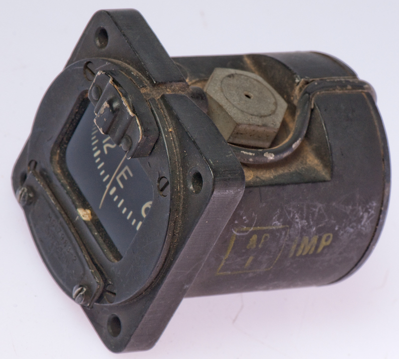 |
Fig 3 |
Fig 4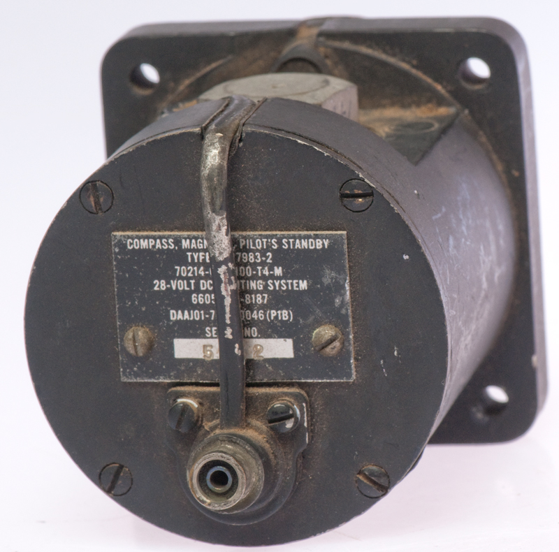 |
Fig 5 top cover for replacing
lamp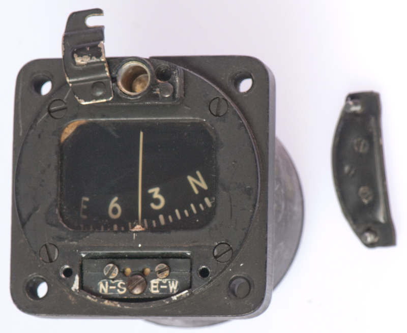 |
Fig 6 bottom cover for deviation adjustment 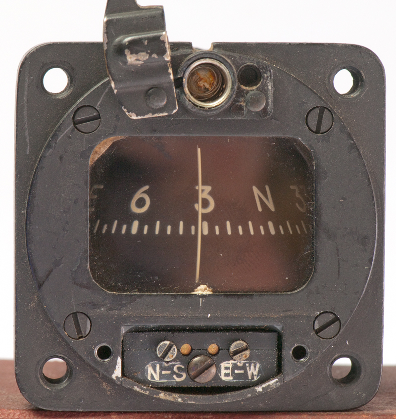 |
Fig 7 UV light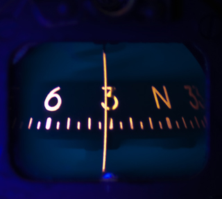 |
Fig 8 UV light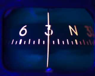 |
Fig 9 |
From The
Navigator - Vol 12 No. 4 Summer 1965
The only equipment required is a brass screwdriver (which is non-magnetic). Naturally, a sextant or astro-compass is used to determine the heading.
First turn the aircraft to a heading of 000°, then read and record the deviation. By means of the N-S compensating screw, take out all of the error until this heading has 0° deviation. Now turn the aircraft to a heading of 090°, record the deviation, and once again remove all deviation by means of the E-W screw on the compensating magnet.
The next aircraft heading is 180° and deviation is again recorded. On this heading, one-half of the deviation is removed by means of the N-S compensating screw. This employs the coefficient system of deviation analysis. Under this system, deviation is resolved into components, of which there are five. The effect of each component is represented by a coefficient. For the purpose of this discussion, it will suffice to say that removing one-half of the deviation will compensate for these coefficients.
Now turn the aircraft to 270° and once again remove one-half of the deviation by means of the E-W compensating screw.
Having removed the deviation on the cardinal headings, now go ahead and swing each 15° around the compass rose.
You’ve completed an important job, but what do you do with the information. Provided for us is the Air Force Form 57 (Pilot’s Compass Correction Card); transpose your information to it and “the pilot’s friend" is ready because of the navigator’s preparedness."
There is also: Standardized Procedures for Performing Aircraft Magnetic Compass Calibration - includes image of Correction card and how to fill it out.
2458022
Altimeter, J.O. Phelps (Airpath Inst Co.), Jan 4 1949, 73/387;
73/178.00R; 116/271; 116/DIG.43 -
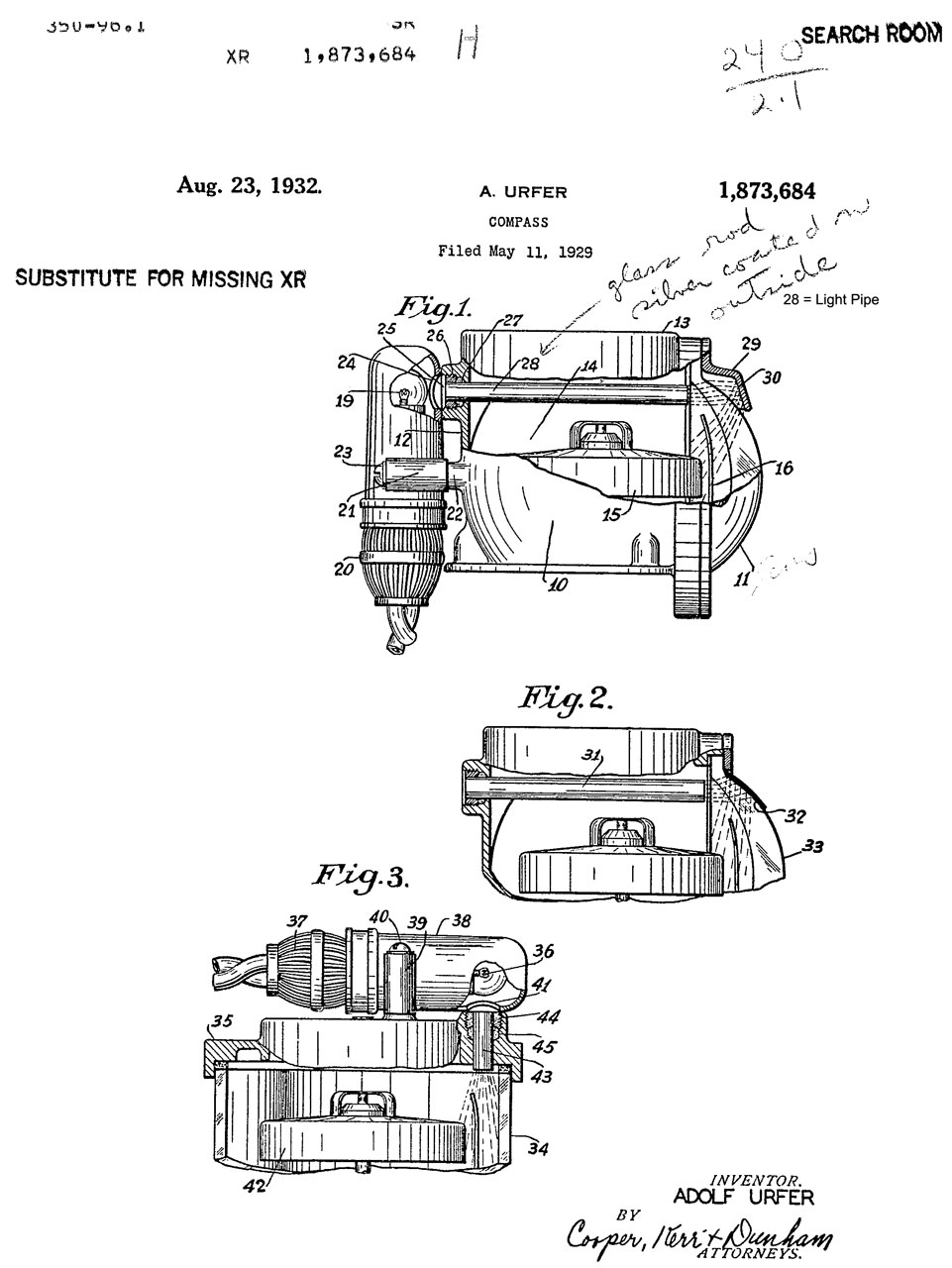 |
1873684 Compass, Urfer Adolf, PIONEER INSTR CO Inc, Filed: 1929-05-11, Pub: 1932-08-23 - Standby Compass light |
| 2041072
Magnetic compass, |
|
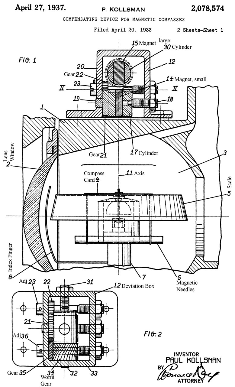 |
2078574 Compensating device for magnetic compasses, The compensation function is contained in a box (12) that can be attached to either the top or bottom. Since the lamp housing is attached to the top the compensation box is attached to the bottom. Note that the centerline of the compensation magnets is in line with the pivot centerline (11). |
Back to Brooke's Products for Sale,
Astronomy, CCD
Astronomy, Sundials, Surveying, Time
& Frequency, Military
Information, PRC68, Alphabetic Index page
Page created June 29, 2012