Navigation Orientation & Position
POS/NAV
© Brooke Clarke,
N6GCE 2001 - 2025
Background
Position
Bearing
Accuracy of Visual Fixes
Gyroscopic
Inertial
Magnetic
Earth
Induction
Optical
Celestial Navigation
Trainer
Pocket (Box) Sextant
Apollo
Program Star List
Brass English Pocket Sextant,
Unsigned, Early 1900's
Stars
Philip Weems
Skylight Compass
Atom Interferometer
Radio
Omega
Bearing
Doppler RADAR
Loran-C
Sputnik
Transit
GPS
GPS
Denied Navigation
Miscellaneous
References
Links
Background
Position
Determining your position on the Earth (or elsewhere) is an
exercise that depends on the interrelationship between time and
position. For example if you know the exact time and can
sight a heavenly body with a Sextant then you can determine where
on Earth you are. If you know were you are, on a Sunny day you can
tell what time it is using a Sundial.
Because of the importance of Navigation at sea the British offered
what today would be a $10 million reward for a clock that would be
practical at sea to find
the Longitude. The pendulum clock would not work at
sea. Harrison spent most of his productive life developing
clocks that would work at sea.
Another maybe more accurate account of the longitude problem is: The True Story of a Lone Genius Who
Solved the Greatest Scientific Problem of His Time
This article makes the valid point that the science was settled
long before Harrison, but the technology was not in place.
Harrison made a marine chronometer that worked, but was way too
expensive to be a viable product. It took a number of
generations of development before marine chronometers were
common. Also note that if a chronometer fails you are lost
and so the method of Lunar Distances (Wiki)
is a way to regain the time while at see.
Finding the Latitude turned out to be an even more difficult
problem. At first glance it would seem that all that's
needed to know your latitude is a sight on the Sun or a
star. But that fails because the axis of the Earth is
wobbling. For navigating a ship the wobble doesn't
matter. But for determining the distance between Earth and
Sun, or make other key astronomical measurements the wobble was a
real problem for almost a century. One of the Latitude Service Observatories is here in
Ukiah, California.
For precision time transfer you need to know where you are then
you can determine what time it is. Because of this radio
based time transfer methods follow the navigation systems.
When Loarn-C was the best nav system it was also the best time
transfer method. Now the GPS system was designed for both
time and position determination and is currently (2002) the best
system for time transfer. See my Time
and Frequency web page for more on time.
Surverying has to do with
determining positions on Earth. Many aspects of astronomy have a strong relation to
time and position.
Bearing
Once you know where you are, you still need to know in what
direction lies your goal. Even today with a GPS receiver
that tells your position, you still need a compass to determine
direction. You can determine direction with GPS by taking a
reading then moving to another location and computing the
direction you traveled, but the GPS receiver when at rest does not
provide any bearing information.
Accuracy of Visual Fixes
Going back well before the chronometer there were pendulum
clocks that keep good time when placed on a solid
foundation. Although they are limited because of changes
in gravity caused by the Sun and Moon (Wiki: Earth tides).
The pendulum clock can be set by observing the Sun and stars and
so can be used to determine Longitude on land when combined with
a transit or theodolite.
The accuracy of the position depends on the accuracy of the time
and the pointing accuracy of the theodolite.
The British Longitude Prize (Wiki)
did not specify the method but rather offered 3 prizes where the
amount paid depended on the accuracy. The range was 60, 40
or 30 nautical miles. These distances are related to the
distance between the lookout at the top of the main mast on a
sailing ship and the peak of a mountain on land. The idea
was to keep ships from running aground which typically killed
all on board. Harrison (Wiki)
won the prize be developing a balance wheel chronometer (Wiki)
because the pendulum clock does not work on a ship. The
basis of determining the longitude at sea at that time
depended on knowing the time to enough accuracy.
When surveying on land your position can be determined using a
theodolite and a source of accurate time. But an efficient
system would match the accuracy of the angle measuring
instrument and the accuracy of the time.
The Earth makes one revolution around it's axis in about 24
hours (about 86,400 seconds Wiki).
Prior to 1967 the period of the Earth was exactly 86,400
seconds, but after that time defined based on a Cesium standard
(see my FTS4060
& FTS4065 web page). The Earth speeds up or
slows down on a daily basis but the Cesium clock keeps much
better time. One revolution of the Earth is equivalent to
a change in longitude of 360 degrees. So we have a
relationship between time and angle.
Unfortunately the units of time and angle are the same for
minutes and seconds so for angle measurements I'll prefix the
unit with arc, like: arc minutes (am) and arc seconds (as).
When using microwave radio frequencies (like the GPS system) or instrumented laser range finding to the Moon or some
GPS satellites there is no "seeing" problem and so the accuracy
can be much better than for visual methods.
Because of the relationship between time, angle and distance
you can see what accuracy you need. For example if using
an instrument with one arc minute of angle accuracy you need a
time standard good for about 4 seconds (one second would be
great), but for a one arc second theodolite you need maybe 50
milliseconds time accuracy.
It's my understanding that there are a handful of stars (the
brightest celestial (Wiki)
navigation stars (Wiki)).
These are the brightest stars, those with the highest magnitude.
Time
|
Angle
|
Distance0
|
24 h
|
360 d1
|
40,030.230141 km
24,873.5821 mi |
1 h2
|
15 d2
|
1667 km
1036 mi
|
4 m
|
1 d
|
1.195 km
69.09 mi
|
1 m
|
15 am
|
27.799 km
17.273 mi
|
3.999457 s
|
0.999864 am
|
1 nmi3
1853 m
6076.12 ft
|
4 s
|
1 am4
|
1853.25 m
1.151 mi
|
1 s
|
15 as
|
463.313 m
1520 ft
|
200 ms
|
3 as5
|
92.663 m
304 ft
|
100 ms
|
1.5 as
|
46.331 m
152 ft
|
66 ms
|
1.0 as6
|
30.888 m
101.3 ft
|
10 ms
|
0.15 as
|
4.633 m
15.2 ft
|
6.6 ms
|
0.1 as7
|
3.089 m
10.13 ft
|
Note: 0: distance along Equator (latitude = 0) (Wiki)
, other constant latitude reduce by COS(|Lat|) or along great
circle through both poles (use number in table).
Note 1: One revolution of the Earth, the speed at the equator is
1667 km/hr, 1036 MPH.
Note 2: Nominal width of a time zone (Wiki)
Note 3: A Nautical mile (Wiki) is
very close to one arc minute of angle.
Note 4: One arc minute is the accuracy of the Wild T16 theodolite which is
about the same accuracy as the Leitz 115
transit.
Note 5: "Seeing" (Wiki),
which varies with time, but on average puts a limit on the
accuracy of any visual observation from Earth of about 3 as. (See:
Stellar Time)
Note 6: One arc second is the accuracy of the Wild T2 theodolite (requires good seeing to
be useful).
Note 7: A tenth of an arc second is the accuracy of the Wild T4
theodolite but that accuracy is used when observing ground based
targets, not astronomical sights.
Gyroscopic
One of the classical uses of gyroscopes
is in aircraft instruments and control systems. The first
inertial navigation systems used gyroscopic stabilized platforms
and today modern flight control systems also use gyroscopes.
In all these cases the gyroscope is used for relatively short
times.
A gyroscope can also be used to determine true North. For example a surveyor
inside a cave can use a North
finding instrument that does not depend on sighting the Sun
or stars yet produces a very precise horizontal angle "fix". The
AG8 is the military nomenclature for one of these systems. The Wild Heerbrugg ARK 1 Gyro
Aiming Circle is another.
Note the drift rate of a
gyroscope, independently of how it works, depends on it's
volume. The gyros on a chip are extremely small and drift
quickly. The huge spinning mass gyros have a much slower
drift rate.
Inertial (Wiki)
Inertial navigation depends on Sensors
for orientation. A classical system uses a three degree of
freedom gyroscopic platform with
accelerometers in each axis. More modern systems use strap
down (Wiki)
fiber optic laser gyros. The
problem is drift. If an inertial system is just placed in a
static location and the position plotted for some time it will
drift. That means that the precision of the "fix" gets
poorer and poorer as time goes by. Inertial systems need
periodic updates using some other method. The Transit satellite navigation
system was designed so Polaris missile subs could update their
inertial nav system.
These systems are typically large and expensive and so you'll
find them on large high value vehicles although I have seen that
the military has a system that can be mounted in a jeep.
2022275
Device for indicating the position of ships, Davis
Arthur Pattison, 1935-11-26, -
2869117
2908902
World-wide navigational system, John
W Gray, Everett
B Hales, Jr
Ivan A Greenwood, General
Precision Laboratory, 1959-10-13, -
3260485
Inertial navigation, Lerman
Harold, Neil
A Sanchirico, John
P Sputz, General
Precision, 1966-07-12, - "In the system of the present
invention, a ground align program or a flight align program may be
selected."
3355942
Man-carried auto-navigation device, Peter
A Freeman, Martin
Marietta, 1967-12-05, - switch in shoe counts steps &
magnetic compass for direction - result integrated.
Magnetic
Compass
Note that in the days of wooden sailing ships a compass worked
rather well. With the advent of steel hull ships getting a
true reading from a magnetic compass became much
harder. Getting a conventional magnetic compass to
work in an armored tanks or submarine is almost
impossible. This was a key motivation for the development
of the Gyroscopic compass.
Lensatic
YouTube: The Map Reading Company:
Use
a Lensatic Compass with a map & without, 16:31 -
Cammenga
compass - how to set magnetic declination, 5:50 -
3 deg per bezel click.
There are 3 types.
The degree dial can be rotated. One application would be
to set it to the local magnetic deviation. Dial in both
degrees (red) and mils (black).
1) This one that has the glow in the dark paint Marked:
U.S. Compass, Magnetic
FSN: 6605-151-6337
RA Miller Elec. Corp.
Grand Haven, Mich.
DAAK01-71-C-8583
30 Jun 71
2) the one with Trintium (Wiki) vials
that glow all the time. Marked:
U.S. Compass, Magnetic
NSN: 6605-01-196-6971 Stocker & Yale 120 mCi
(millicuries of tritium)
|
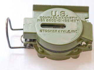
U.S.
COMPASS, MAGNETIC
NSN 6605-01-196-6971
STOCKER & YALE, INC.
|
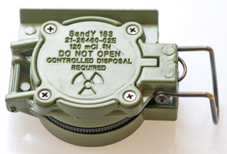
SandY 183
21-26460-02E
120 mCi 3H
DO NOT OPEN
CONTROLLED DISPOSAL
REQUIRED
|
NSN: 6605-01-196-6971 3H
Cammenga (probably 120 mCi). comes in OD, Black or Camo.
3) a version of the Trintium compass for Japan with a smaller
amount of Trintium.
3HJP with 27 mCi
2111829
Orientation Compass, F. Winterer, Mar 22, 1938, 33/272; 33/285
Brunton
Truarc
3 Baseplate Compass Global Needle
Fig 1
 |
Fig 2
 |
Fig 3
 |
Fig 4
 |
Fig 5 Declination adjusted to about 13
deg East for N. California
Note camera was not square to compass so parallax makes
it look
more like 18 degrees East. Maybe best adjusted
under a miroscope
to be sure viewpoint is square to compass?
 |
|
I wanted a compass where the declination is made as an
adjustment, so you do not need to think about it with every
sighting. This has adjustable delineation, and the added
bonus of a global needle ( the words "Global Needle" are
adjacent to needle not on it).
Note the Tempest
weather station needs to be aligned to True North.
From NOAA
WMM-2025 or my location and 2025 Jan 21 the declination is
13 deg 24 min E. Of course sighting the North
Star will work.
YouTube: Brunton
Compass - how to set magnetic declination, 6:48 -
4438568
Recreational compass, Melvin
G. Kramer, Marlin
Iden, Brunton
Co, 1984-03-27, - box mirror TruArc 15,
but not global needle
US Army Corps of Engineers compass (searching for patent)
|
GB189619600
An Improvement in and relating to Divided Circles for
taking Bearings and such like purposes, Gilbert
Legh, 1897-07-10 -
Slit with sighting hair in compass lid,
but no rear sight.
|
|
736925
Instrument for ascertaining direction in marching or
traveling Johann Von Bezard, 1903-08-25, -
|

|
920587
Compass, Anton
Laube, 1909-05-04, -
|

|
994901
Surveying and cruising instrument, Joseph
Barbow, 1911-06-13, -
|

|
GB103742
(eSpaceNet)
Improvements in Day and Night Compasses, Gilbert Legh,
1917-02-08, -
K & L: Glass and index line near eye sight through
Metallic lid H carries a lens J for reading the scale
and a slit for sighting an object.
The screw O is used to lock and unlock the compass card.
|

|
2108263
Compass, L
Abee-Lund Johan Henrik, Abee
Lund As, 1938-02-15, - user adjustments for
declination and dip. |

|
2111829
Orientation Compass, F. Winterer, Mar 22, 1938, 33/272;
33/285
|

|
2336789
Compass, particularly for orientation purposes, Jonsson
Arvid, 1943-12-14,
|

|
2336790
Orientation compass, Jonsson
Arvid, 1943-12-14, |
|
2487044
Compass, W.C. Cude (US Army), Nov 8 1949, 33/348;
33/345; 33/349; 33/354; 33/357 - Army Corps of Engineers
Lensatic Compass -second version with copper dampening
cup and white case interior.
Case (1) is stamped aluminum.
Copper cup (31) supports conical pivot (32). The
cup may be of other electric conductive material, and
also may be in the form of a ring. The pivot (32)
Supports a jewel mounted magnetic needle (33) having a
length slightly less than the diametric measurement of
the cup (3) for maximum flux cutting by the cup and to
accommodate slight tilt angles, Such as 8 to 10
degrees. The lensatic form has the interior of the
cup (3) coated with a light reflective material such as
White enamel, and a luminous segment (56) provided
therein to assist in night reading.
Bezel ring (5) has 120 serrations (3 degrees per click).
Calls:
GB191029677
(eSpaceNet)
Improved Means for Illuminating Compasses,
Clinometers, and the like, Francis Barker & Son
Ltd, 1911-10-19 -
probably radium paint below transparent dial
GB191314083
(eSpaceNet)
Improvements relating to Magnetic Compasses and like
Instruments, Edwin Weeks Barker, 1914-03-19 - uses
a radium compound for the illumination
GB191501818
Improvements relating to Magnetic Compasses, Francis
Barker & Son Ltd, 1915-11-04 - inside
of cover has luminous line and seperate sighting hole
with wire.
2003179
Magnetic Compass, H.T. Faus (GE), May 28 1935, 33/345;
33/355.00R; 318/466; 318/647; D10/68 - uses 2
cylindrical bar magnets. The composite bars
comprise a central portion of high permeability
material and end portions of high coercive force
material. In this manner, the magnetic leakage flux is
concentrated at the ends of the composite bars and the
central portions of the bars are easily machinable to
permit mounting of jewels or bearings for pivoting.
The compasses are preferably mounted in cups of
electrically conducting material coaxial with the
pivot axis for the purpose of damping vibrations by
the absorption of the energy of vibration as eddy
currents in the electrically conducting material.
FR782576
(eSpaceNet) Compass refinements, 1933-12-11 - Base
plate design, celluloid used to contain fluid to allow
for expansion.
GB445312
(eSpaceNet)
Improvements in and relating to compasses, Gunnar
Tillander, 1936-04-07 - ribs inside the celluloid
capsule help keep the fluid from rotating on this base
plate compass.
This may be the same as the US Army Corps of Engineers
Field Compass W.W.II. no date

|
Model 1938 lensatic compass
Early model, no dampening.
Later models with dampening have white
background on the compass card.
The M1950 has the look and feel of today's
Cammenga 3H.
|
The surplus stores sold a cheap compass that looked very
much like this.
|

|
2528339
Cruiser's compass, Collins
Reginald, 1950-10-31, - non-magnetic needle for
pointing to objective, transparent bottom base plate,
|
|
2680297
Pocket compass, Vaucher
Eric, 1954-06-08, -
Suunto
MB 6 Global -
Suunto
MB 6 Instructions + improved military boxing technique,
21:05
|

|
2824382
Compasses, Sandberg
Nils Henry, 1958-02-25, - means for
rotatably se curing the compass-box to the ruler. |

|
4920656
Compass assembly with dial biasing disk, Gregory
L. Cross, Sunoco,
1990-05-01, -
|

|
5233759
Compensating magnetic compass, Hans
Gloor, Denis
Gigon, Recta
AG, 1993-08-10, - World Needle
|
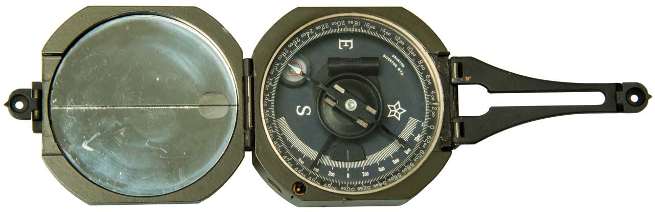
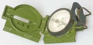
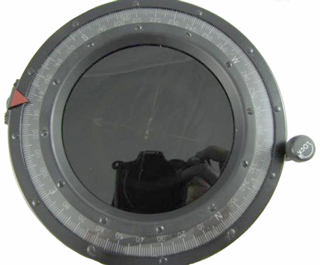
M2 Pocket Transit Compass (Brunton)
This is a very high quality compass and
inclinometer. There are two versions of the dial, one is
in degrees and the other is in Mils. Which is the
military degree measurement used for artillery, it is
equivalent to 1 yard at a range of 1,000 yards. For most
compass uses the degree version is much more useful, but all
the military M2 compasses are in Mils. Mils is for milli
radians (Wiki).
1 yard offset at 1,000 yards is 1 mil (NATO).
The degree dial can be rotated relative to the compass
body. On mine, shown above, I've offset the dial my the
local magnetic variation (Wiki). That way when the North
pointer is at zero the compass is pointing to True North
rather than Magnetic North.
TM 9-1596 Compass M2, 28 pages. PB 3214 - BSIR 1(9):385;
03/08/46 (Radio Nerds pdf)
TM 9-1290-333-15 Operator, Organizational, Field and Depot
Maintenance Manual, Compass, Magnetic, Unmounted: M2, 7 Nov
1963. (Liberated
Manuals pdf)
You can still buy this from Brunton in a number of
different sizes it was originally patented by Brunton:
526021
Pocket-transit, David
W. Brunton, Sep 18, 1894, 356/142
; 33/285; 356/147 -
1042079
Transit, David
W Brunton Oct 22, 1912, 33/272, 356/143 -
1062582
Transit, David
W Brunton, May 27, 1913, 33/272
1092822
Sight for transits and similar
instruments, David
W Brunton, Apr 14, 1914, 356/143, 356/142, 356/147
and later a version was patented by K&E
1571697
Transit,
Bernegau
Carl M (Keuffel
& Esser Co), Feb 2 1926, 33/273, 33/352
There are a large number of replica "Brass" versions now for
sale, who knows if they are even functional.
The M2 was/is used to setup artillery, mortar
and other sites where you need a good magnetic bearing and
also for rough field survey work.
1223615 Pocket
Surveying Instrument, R.W. Richards, Apr 24 1917, 56/143 -
1339019
Illuminated Transit, D.W. Brunton, May 4 1920, 40/542; 33/285;
250/462.1 -
4395828
Combination
geodetic transit compass and signal mirror,
Allan P. Juhas, Aug 2, 1983,
33/272,359/516,33/275.00R,116/20,33/348,359/558
4700490
Compass, Melvin
G. Kramer, Marlin
D. Iden, Brunton
Co, 1987-10-20, - Global disk
4175333
Compass, Melvin
G. Kramer, Brunton
Co,1979-11-27, - design for Global operation and
ruggedness
6516526
Pocket transit, Marlin
D. Iden, Brunton
Co, 2003-02-11, - Geo
(Axis?)
Transit
Marching
The
Francis Barker M73
is a Marching compass. I have asked them the size of a
division since the data sheet says "accuracy by reading: one
half of one division" but they did not say how man degrees
in a division. From photos it looks like 5 degrees per
division, so accuracy may be 2.5 degrees?
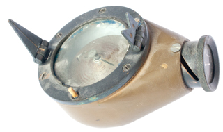
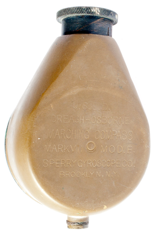
Sperry Gyroscope Creagh Osborne Marching Compass
MKVII Mod. E
|
|
|
U.S.E.D.
(United States Engineering Department)
Creagh-Osborne
Marching Compass
MKVII Mod. E
Sperry Gyroscope Co.
Brooklyn, N.Y.
|
1216953
Magnetic Compass, F.O. Creagh-Osboren & A.J. Hughes, Feb
20 1917, 33/348; 33/364; 250/462.1; 359/441; 362/29 -
1256442
Magnetic Compass, F.O. Creagh-Osboren & A.J. Hughes,Feb 12
1918, 33/350; 33/357; 33/364 -
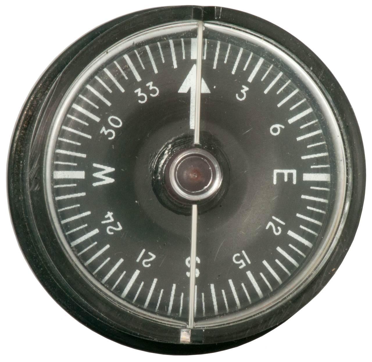
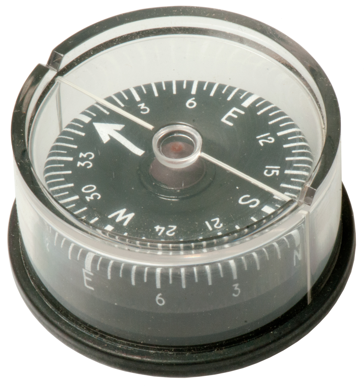
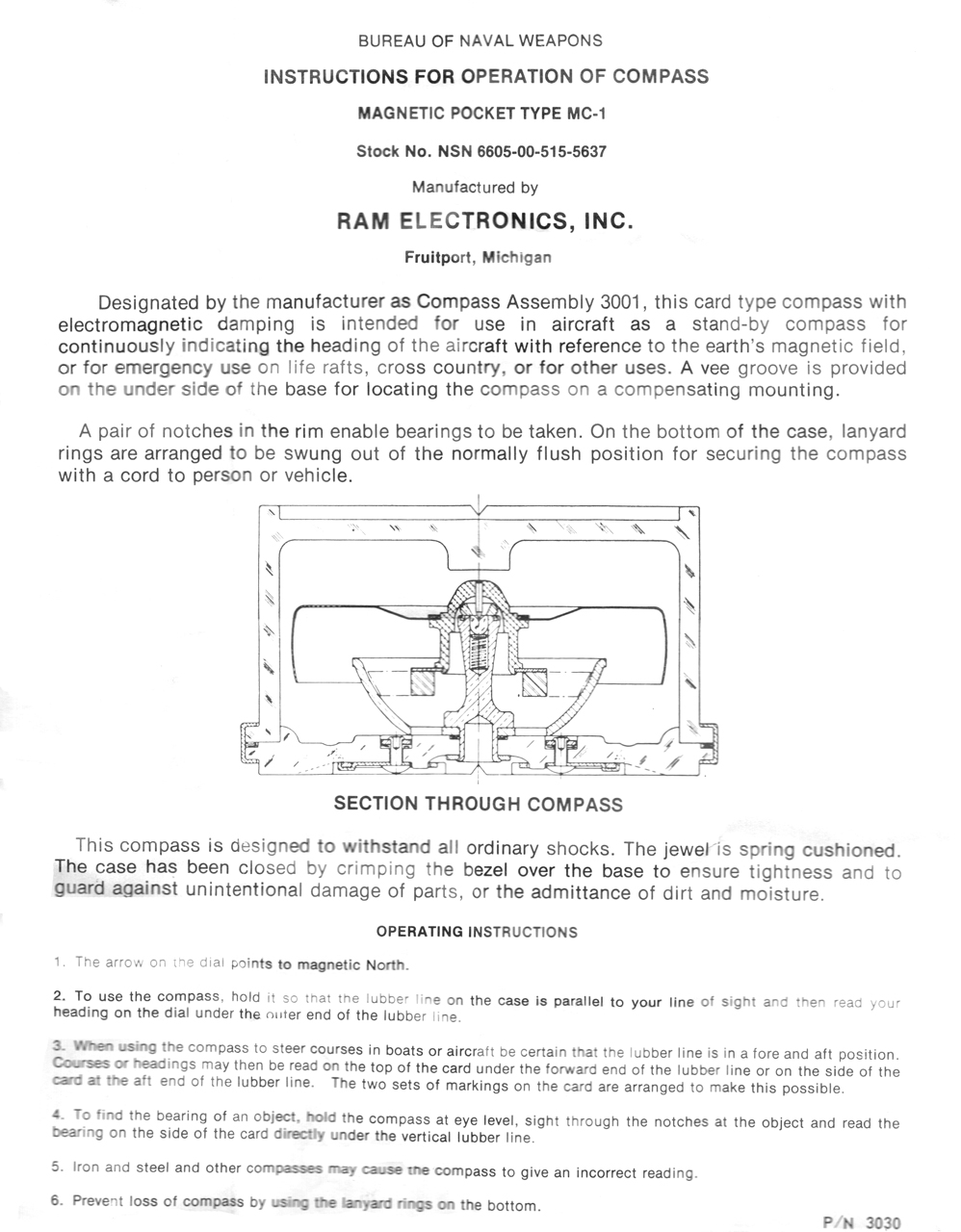
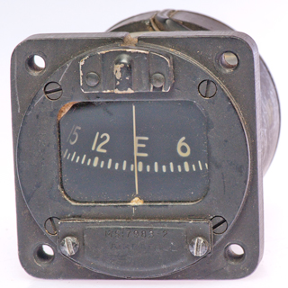
MC-1 Magnetic Compass Flight line
Calibration Set
Works with 400 Hz "Y" connected synchro type sensors
and indicators as used in aircraft.
Flux Valve is the name associated with the sensors.
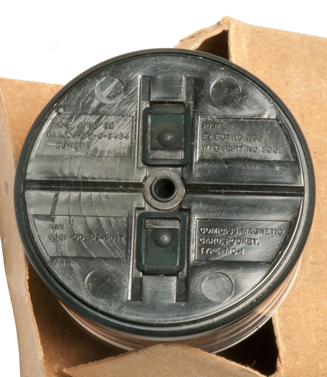
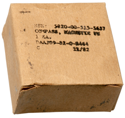
Type MC-1, Compass Magnetic, Card,
Pocket, NSN: 6605-00-515-5637
04 June 84
DAAJ 09-82-C-B464
|
Fig 1 NSN: 5820-00-515-5637?
Contract date: 11/82
|
Fig 2
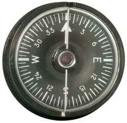 |
Fig 3 There appear to be "dots" making
up all the white marks, but they do not glow in the
dark or glow after shining a bright light. What
are they? let me know.
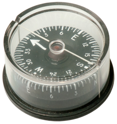 |
Fig 4 Compass Magnetic, Card, Pocket,
Type MC-1 NSN: 6605-00-515-5637
04 June 84
DAAJ 09-82-C-B464
 |
Instruction Sheet
|
Looking for a patent covering electromagnetic dampening of a
compass. let
me know the patent number.
2350402
Magnetic direction indicating instrument, Krasnow
Shelley, Joseph
M S Kaufman,1944-06-06, - liquid card type, but balanced
moments of inertia for faster response.
|
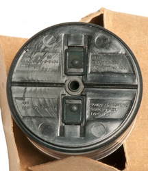
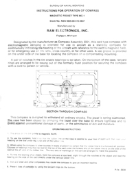
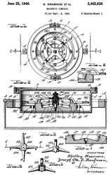
2402638
Magnetic compass, Krasnow
Shelley, Joseph
M S Kaufman, App: 1941-09-04, (W.W.II)
Pub: 1946-06-25, - electromagnetic damping instead of
liquid
Joseph Kaufman has other Compass patents, including
for the SC-1 Abrams Sun
Compass.
2505776
Method of manufacture of hollow floats of thin metal
for ship compasses, Joseph
M S Kaufman, Krasnow
Shelley, Josef
A Schaerfi, App: 1941-07-11, (W.W.II) Pub:
1950-05-02 - mentions filling etched lines &
numerals may be filled with luminous material.
So that may explain the appearance of them.
|
2638683
Magnetic compass, John
B Reece, John
P Putnam, Reece
Corp, 1953-05-19, - "dead beat", electro-conductive
dampening
3082663
Multi-purpose magnetic pocket compass, Zweifel
Peter, 1963-03-26, - liquid dampening
Surveying
The surveying transit evolved from a compass coupled
to a telescope. Almost all transits have a compass built
in so that magnetic North can be indicated and true North can
then be determined. Because of this the frame must be non
ferrous. Most are brass.
Leitz 115A Transit
M3 Coil Magnetic Survey
Instrument & Ruska
Helmholtz Coil for calibration
Wrist Computer
Vector
by Suunto - contains clock
with time, date, alarms, magnetic compass, barometric pressure
& altitude as well as temperature.
info wanted on this
unit
Type 1811-1-B Aircraft Flux Gate Compass
2188821
Compass, Bendix Aviation, Jan 30, 1940, 362/30; 33/348;
246/1.00C; 385/147 - illumination Looks like Type 188-1-B
1939374
Liquid Compass, A. Urfer (Pioneer Instrument Co), Dec 12, 1933,
33/364 - allow for expansion/contraction of fluid.
1679764
Magnetic Compass, Charles
H Colvin, Pioneer
Instrument, 1928-08-07, 33/364 - improved magnetic element
1334273
Magnetic Compass, C.H. Colvin, Mar 16 1920, 33/364 -
readable from side or top for aircraft use
1983103
Magnetic Compass, C.L. Seward Jr (Bendix Aviation), Dec 4, 1934,
248/638; 33/350 - aircraft shock absorbing and keeping the card
from spinning
1873684
Compass, A. Urfer (Pioneer Instrument Co), Aug 23 1932, 33/348;
33/555; 246/1.00C; 385/147 - light pipe to liquid aircraft
compass
2008475
Spring Mounting, G. Spiller (Bendix Aviation), Jul 16, 1935, -
aircraft use pivot pin support
1910092
Instrument Cover Glass, C.H. Colvin (Pioneer Instrument Co), May
23, 1933, 362/23; 33/364; 359/601 - old convex glass reflects
light
2008481
Magnetic Compass, P.F. Weber, W.E. Dankau (Bendix Aviation), Jul
16, 1935, 33/364 -
2127807
Indicating Instrument, V.E. Carbonara (Bendix Aviation), Aug 23,
1938, 116/287; 33/348; 116/299; 359/440 -
1596639
Compass for Navigation Purposes, Vion
Eugene, , Aug 17, 1926, 33/359; 324/244 -
2222627
Compass, Naecker
William, 1940-11-26, - 4 magnetic rods that can be
adjusted.
Bendix D-12 Compass
The list of patents on the D-12 appears to be the same as the
list on the Type 1811-1-B.
1596639 Compass for navigation purposes, see above
1679764 Magnetic compass, see above
1873684 Compass, see
above
1910092 Instrument cover-glass see above
1939374 Liquid compass see above
1983103 Magnetic compass see above
2008475 Spring Mounting, see above
2008481 Magnetic Compass, see above
2127807 Indicating Instrument, see above
2188821 Compass, see
above
1474394
Magnetic compass, James
P Warburg, US
Government, 1923-11-20, -
2003179
2127878
1334273
Earth Induction
Compass (Wiki)
Earth Induction Compass
(see Magnetics) - a coil rotating in
the Earth's filed was used for the first half of 1900s as an
aircraft compass.
Also see Pioneer Instrument Co
- acquired by the Bendix Aviation Corporation (Wiki)
in 1928.
1047157 Device for Determining
Direction, D.M.
Bliss, Dec 17, 1912, 33/362; 324/257 - The Earth
provides the magnetic filed and a rotating coil (could be
powered by the air going past an airplane) generates a voltage
that depends on the relative heading of the plane.
1472342
Electromagnetic compass, Pickard
Greenleaf Whittier, Wireless
Specialty Apparatus, 1923-10-30, 33/362; 324/257 -
1886336
Induction compass, Gunn
Ross (Wiki),
1932-11-01, -
1963551
Inductor compass, Gunn
Ross, Bendix
Research Corp, 1934-06-19, -
1970543
Navigating instrument, Victor E Carbonara, Pioneer Instr Co Inc,
1934-08-21, 356/148; 33/348 -
2054318
Compass, Gunn
Ross, 1936-09-15, -
2434324
Earth Inductor Compass, H.
Ledhe, Control
Instrument Co, Jan 13, 1948, 33/362; 318/647 - crystals
vibrating to move sense coils
Tank
eBay listing "WW2 ARMORED VEHICLE COMPASS , TANK , LANDING
VEHICLE , ETC. Pioneer instruments" has photo with these patent
numbers:
2188821
Compass, Gregory V Rylsky, Bendix Aviation Corp,
1940-01-30 - illumination
Bendix
Aviation Corp,
1679764
Magnetic compass, Charles H Colvin, PIONEER INSTR Co, 1928-08-07
- compass card construction
1873684
Compass, Urfer Adolf, PIONEER INSTR Co, 1932-08-23
- illumination
1910092
Instrument cover-glass, Charles H Colvin, PIONEER INSTR Co, 1933-05-23
- special shape to minimize reflections and allow lighting
1939374
Liquid compass, Urfer Adolf, PIONEER INSTR Co, 1933-12-12
- expansion chamber
1983103
Magnetic compass, Jr Clarence Lee Seward, Bendix Aviation Corp,
vibration reducing mounting
2008475
Spring mounting, Spiller Gerhard, Bendix Aviation Corp, 1935-07-16
- vibration reducing mounting
2008481
Magnetic compass, Philip F Weber, Walter E Dankau, Bendix Aviation Corp,
1935-07-16 - card buoyed by liquid and jeweled bearing
2127807
Indicating instrument, Victor E Carbonara, Bendix Aviation Corp,
1938-08-23 - feels like the standby compass,
illumination
1596639
Compass for navigation purposes,Vion Eugene , 1926-08-17 -
compensation for vehicle hard & soft errors - the key for a
Tank compass (if possible?)
2227368
Illuminating adapter for instruments, Gregory V Rylsky, Bendix Aviation Corp,
1940-12-31 - add-on illumination
These are very accurate British military compasses, but not
for use with map a map.
GB190915472
eSpaceNet
An Improved Instrument for Surveying and like purposes, Francis
Barker and Son, 1910-07-04, - for surveying
GB191322499
eSpaceNet
An Improved Pocket Theodolite, Francis
Barker & Son, 1914-07-23, - for surveying
GB191501818
eSpaceNet
Improvements relating to Magnetic Compasses, Francis
Barker & Son,1915-11-04, - folding pocket compass,
radium dots, round case, not straight edges.
By manually sighting a star or the Sun the direction
of true North can be determined. This instrument was
typically used in aircraft and was held in a "bubble"aka
dome requiring the optical distortion effects of the
bubble to be corrected.
The periscope was mounted in a hole in the top of the
plane and was out in the outside air. It thus did not
require any "bubble" correction and was much easier to
use. A huge improvement over the classical nautical
sextant (Wiki)
is the inclusion of a clockwork averager that makes the
resulting elevation measurement more accurate.
This unit has a star tracker assembly with its own
glass "bubble" and is pressurized, probably with dry Nitrogen,
to prevent fogging of the optics. It has a larger prism at
the objective end than the periscopic sextant, probably to
gather more light for the photomultiplier tubes that detect the
star. This model may not be able to track stars in the
daytime, but later versions could.
Transit Surveying Instruments
For centuries surveyors have used the Sun and stars to
determine true North. To do this there are attachments for
transits to allow imaging the Sun without damage to the users
eye(s).
Leitz 115A Engineers Transit
uses the older 3½" x 8 thread tripod
Similar to the transit but with the addition of optical angle
readout instead of Vernier readout. See Dividing Engines.
This allows much more precision.
This is a very early square tube unit with no optics
except for a first surface mirror to view the bubble from the
bottom. I think is was build is such a way as to avoid the
Locke patent
7477 hand level that K&E later offered after the
patent ran out.
Compact tripod mounted leveling scope with cross hairs
and spirit level, with 1884 patent 297164
date. In a patented seamless leather box.
These instruments are similar to a surveyors transit
except instead of mounting on a tripod they are held by a
ruler. There is no horizontal angle measuring ability,
instead a ruler parallel to the line os sight is used to draw a
line on the map directly in the field. The method of Stadia is used to determine the
distance to the rod. This was the primary tool used in the
U.S. to make topo maps for many years.
K&E 76 0000 Alidade -
self indexing (auto leveling) and built in trig for horizontal
and vertical distance based on stadia
reading.
Celestial Navigation Trainer _ moved to Aircraft
- also see Aircraft\Simulators
which has many more Link patents related to celestial
navigation.
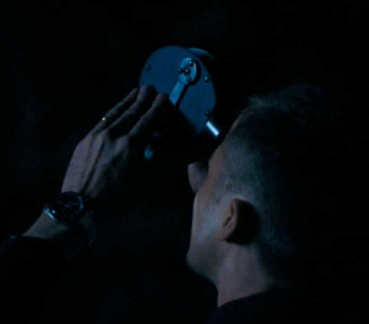
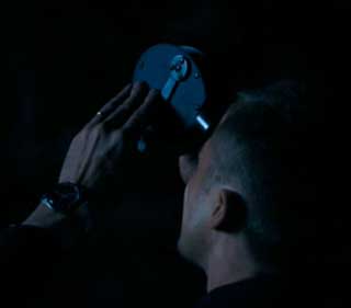
Pocket (Box) Sextant
This appears in the movie First Man (IMDB, Wiki)
at 39:11 with Neil Armstrong, sighting the moon with a Box
Sextant but used in the conventional manner, i.e. measuring
the angle between the moon and and the horizon. But
there is little if any benefit in doing that. On the
other hand if he was making lunar distance (Wiki)
measurements between the moon and a star, or better
measurements between two navigation stars that would be
excellent practice in finding the navigation stars that were
the heart of the Apollo Guidance Computer (AGC) (Wiki).
YouTube:
Apollo AGC Part 1:
Restoring the computer that put man on the Moon - a 23
part series that follows the effort that got it
working.
The main inputs to the Apollo Guidance Computer are a
Sextant and gyroscope
based Inertial Measurement Unit (IMU).
Note the Wiki lunar distance page shows a vertical
measurement, but most lunar distance measurements have the
sextant in a horizontal position. Someone
practicing Celestial navigation for space (Wiki)
would be concerned about the angle between two navigation
stars. Note that there is no horizon when you are in space.
I don't think calling this a sextant is correct since a
sextant typically measures an angle between a star and the
horizon. They often include artificial horizon
capability. While a conventional sextant can be used to
make lunar distance measurements, it is heavier than needed
and so not optimized. The box sextant has nothing
special for the horizon and so maybe could be called a
transit? There is no horizon in space.
YouTube: Computer for
Apollo 29:05 -
YouTube: Apollo Program Guidance
and Naviagtion Systems 79974; 6:39 - video of view
through AGC sextant.
Space Craft Archive: The
Star Charts of Apollo -
Smithsonian - Apollo
Sextant and Eye Piece - Navigating
In Space - Star
Chart (Navigation stars are larger and have a 2-digit code
for the computer. The Earth is huge.) - Time
and Navigation.ppt - Apollo
Guidance Computer (MIT)
-
NASA: Apollo
Operations Handbook, Section 2, Subsection 2.2, Guidance and
Navigation (G&N).pdf - Apollo
Documents - The
Apollo Lunar Module Alignment Optical Telescope -
New atlas: Apollo’s
brain: The computer that guided man to the Moon -
Humboldt State University: Drum
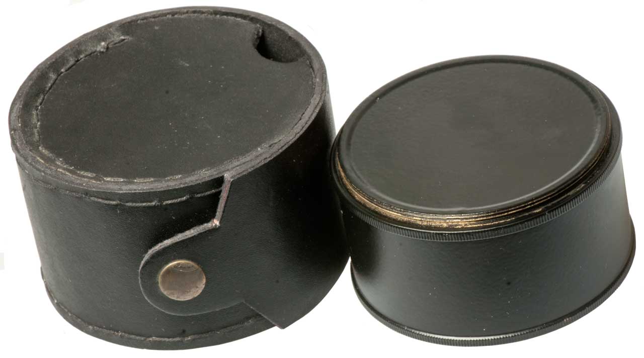
(“Snuffbox”) Sextant & Leather Case - 1797
Description of a New Pocket Box Sextant, and an Artificial
Horizon, by the Editor.pdf -
Geometrical
and Graphical essays, containing, a general
description...Box Sextant.pdf
Frederick Walter Simms, A Treatise on the
Principle Mathematical Instruments Employed in Surveying,
Leveling, and Astronomy, Troughton & Simms, London
(1834).pdf
Sextant Book: A
Francis Barker Yachting Sextant -
India Reproductions: Brass Compass:
Box Sextants -
YouTube: Build an
electroluminescent glass panel display -- an Apollo DSKY
"dis-key" - DiSplay
KeYboard - Wiki
-
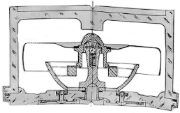
Description
The mechanism is very similar to a split
image rangefinder. Except instead of the calibration
being in distance it is an angle in degrees.
Patents
213018
Improvement in surveying-instruments, H.S.S. Watkin, Mar 4, 1879
- A rangefinder packaged "like an
ordinary box sextant".
eBay seller: marineantiques16
- Items for sale - This is a high quality item, not
the normal made in India cheap brass.
First Man (IMDB,
Wiki)
39:11
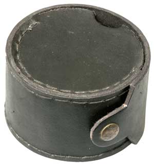
|
Reproduction Box Sextant from eBay seller
marineantiques16
eBay title: "Antique Maritime Brass Pocket Sextant
Vintage Working Drum Box Sextant in Cover" 232430184445
"This is a Reproduction Item, Not Sold As Antique." |
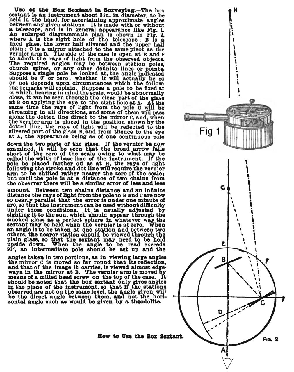
Cassell's
Cyclopaedia Of Mechanics
- Use
Of The Box Sextant In Surveying -
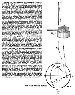
|
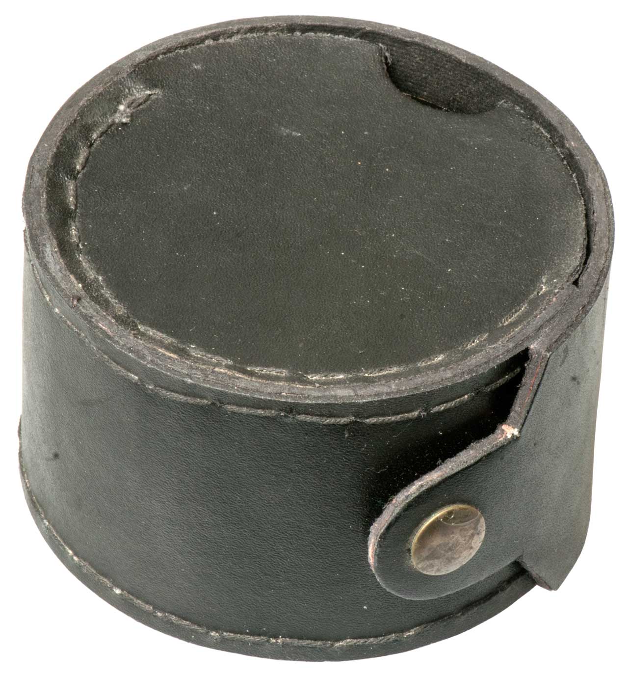
Fig 1 Leather case 3-12" dia x 2"
thick, 1 # 6 oz.
|
Fig 2Brass box 3" dia x 1-1/8" thick.
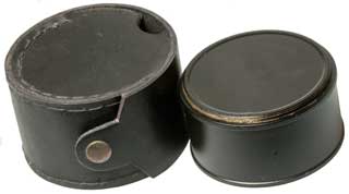 |
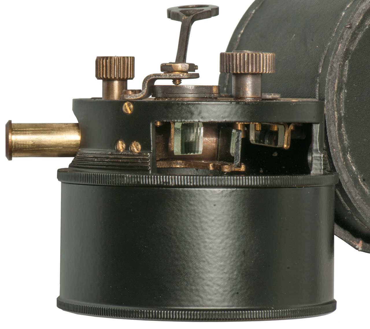
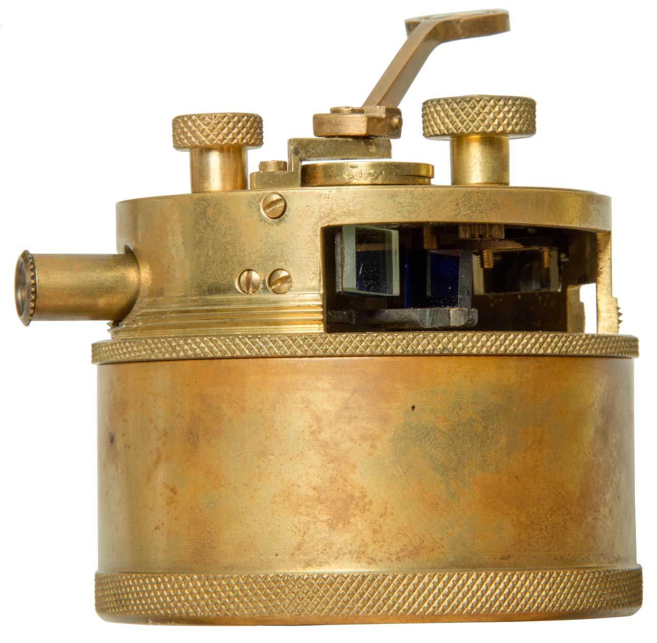
Fig 3Verneer scale magifing glass folds
down.
The lever at 5 O:clock is for a sun filter.
Knob at left is wrench for square peg adjustments.
Large knob at right turns measurement mirror (C).
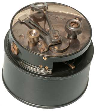 |
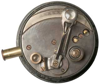
Fig 4 Measuring Mirror (C) at left,
filter at center,
Fixed Mirror (B) at right.
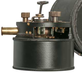 |
Fig 5
 |
|
Apollo Program Star List
The Apollo stars are numbered in order of Right Ascension (Wiki)
(left to right on the star chart). They appear to be
Octal numbers (Wiki),
not decimal.
In the right column is a modern list of 58 navigation stars (Wiki).
USNO - Navigational
Star Chart - prints on 11 x 8.5 paper.
In addition to the list of stars there were also 19
Lunar Landmarks and Earth Landmarks.
On 1 July 1969 at 1530 EDT Program 23 CisLunar was used to
sight stars 02, 40, 44, 44 & 45. Reference Final
Apollo Flight Plan, July 1, 1969, pg 3-7.
In Apollo
Navigation, Guidance, and Control Systems: A Progress Report
by David Hoag April 1969 there is a little discussion of
how well the AGC compared with the gold standard ground
tracking radars. Pretty good agreement.
MIT Instrumentation Laboratory: Space Guidance Analysis
Memo #34-64 "Orbital Navigation Using Unknown Landmarks" Aug
20, 1964 - it turns out this is very difficult if not
impossible because of the speed of the space vehicle relative
to the Earth.
Apollo
#
|
Name (Wiki)
|
RA
|
Dec
|
Nav
Star List
#
USNO
|
00
|
Planet
|
|
|
|
01
|
Alpheratz
|
00h 08m 23.25988s |
+29° 05′ 25.5520″ |
1
|
02
|
Diphda
|
00h 43m 35.37090s |
–17° 59′ 11.7827″ |
4
|
03
|
Navi
|
00h 56m 42.50108s |
+60° 43′ 00.2984″ |
na
|
04
|
Achernar
|
01h 37m 42.84548s |
–57° 14′ 12.3101″ |
5
|
05
|
Polaris
|
02h 31m 49.09s |
+89° 15′ 50.8″ |
<not numbered>
|
06
|
Acamar
|
02h 58m 15.67525s |
−40° 18′ 16.8524″ |
7
|
07
|
Menkar
|
03h 02m 16.77307s |
+04° 05′ 23.0596″ |
8
|
08
|
<not used>
|
|
|
|
09
|
<not used>
|
|
|
|
10
|
Mirfak |
03h 24m 19.37009s |
+49° 51′ 40.2455″ |
9
|
11
|
Aldebaran
|
04h 35m 55.23907s |
+16° 30′ 33.4885″ |
10
|
12
|
Rigel
|
05h 14m 32.27210s |
−08° 12′ 05.8981″ |
11
|
13
|
Capella
|
05h 16m 41.35871s |
+45° 59′ 52.7693″ |
12
|
14
|
Canopus
|
06h 23m 57.10988s |
−52° 41′ 44.3810″ |
17
|
15
|
Sirius
|
06h 45m 08.91728s |
−16° 42′ 58.0171″ |
18
|
16
|
Procyon
|
07h 39m 18.11950s |
+05° 13′ 29.9552″ |
20
|
17
|
Regor
|
08h 09m 31.95013s |
–47° 20′ 11.7108″ |
na
|
18
|
<not used>
|
|
|
|
19
|
<not used>
|
|
|
|
20
|
Dnoces
|
08h 59m 12.45362s |
+48° 02′ 30.5741″ |
na
|
21
|
Alphard
|
09h 27m 35.2433s |
−08° 39′ 30.969″ |
25
|
22
|
Regulus
|
10h 08m 22.311s |
+11° 58′ 01.95″ |
26
|
23
|
Denebola
|
11h 49m 03.57834s |
+14° 34′ 19.4090″ |
28
|
24
|
Gienah
|
12h 15m 48.37081s |
–17° 32′ 30.9496″ |
29
|
25
|
Acrux
|
12h 26m 35.89522s |
−63° 05′ 56.7343″ |
30
|
26
|
Spica
|
13h 25m 11.579s |
−11° 09′ 40.75″ |
33
|
27
|
Alkaid
|
13h 47m 32.43776s |
+49° 18′ 47.7602″ |
34
|
28
|
<not used>
|
|
|
|
29
|
<not used>
|
|
|
|
30
|
Menkent
|
14h 06m 40.94752s |
–36° 22′ 11.8371″ |
36
|
31
|
Arcturus
|
14h 15m 39.7s |
+19° 10′ 56″ |
37
|
32
|
Alphecca
|
15h 34m 41.268s |
+26° 42′ 52.89″ |
41
|
33
|
Antares
|
16h 29m 24.45970s |
−26° 25′ 55.2094″ |
42
|
34
|
Atria
|
16h 48m 39.89508s |
–69° 01′ 39.7626″ |
43
|
35
|
Rasalhague
|
17h 34m 56.06945s |
+12° 33′ 36.1346″ |
46
|
36
|
Vega |
18h 36m 56.33635s |
+38° 47′ 01.2802″ |
49
|
37
|
Nunki
|
18h 55m 15.92650s |
–26° 17′ 48.2068″ |
50
|
38
|
<not used>
|
|
|
|
39
|
<not used>
|
|
|
|
40
|
Altair
|
19h 50m 46.99855s |
+08° 52′ 05.9563″ |
51
|
41
|
Dabih
|
20h21m00.7s |
−14°46′53″ |
na
|
42
|
Peacock |
20h 25m 38.85705s |
−56° 44′ 06.3230″ |
52
|
43
|
Deneb
|
20h 41m 25.9s |
+45° 16′ 49″ |
53
|
44
|
Enif
|
21h 44m 11.15614s |
+09° 52′ 30.0311″ |
54
|
45
|
Fomalhaut
|
22h 57m 39.0465s |
−29° 37′ 20.050″ |
56
|
46
|
Sun
|
|
|
|
47
|
Earth
|
|
|
|
48
|
<not used>
|
|
|
|
49
|
<not used>
|
|
|
|
50
|
Moon
|
|
|
|
Note: Apollo star numbers ending with 8 or 9 are not
used. That implies that the computer used octal numbers
(Wiki)
rather than decimal numbers.
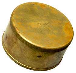
Brass English Pocket Sextant,
Unsigned, Early 1900's
From an estate sale (garygermer: The
Peter Abrahams Science & Astronomy Estate) that
included telescopes, binoculars, surveying instruments and
other optics.
At the bottom of the lid was a copy of "The Box or Pocket
Sextant" from The Civil Engineer's Pocket Book (pg 297 <pdf
pg 370>. BepSextant.pdf
Fig 1 The bottom of the sextant is
threaded so
the can will screw onto the bottom
Stamped: "No 3511"
|
Fig 2 Telescope needs to be pulled out
just the
right amount to focus. The magnifying glass
hinges up to read scale.
 |
Fig 3
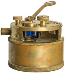 |
Fig 4 Alignment tool sitting on an square
pin.
 |
|
|
Patents
Class
356/20: Optics: Measuring and Testing: Range or Remote
Distance Finding\External basis type
213018
Surveying Instrument, H.S.S. Watkin, 1879-03-04, 356/20 - oldest U.S.
patent in class 356/20 - in rectangular box
504869
Instrument for Measuring Distances and Solving Trigonometrical
Problems, E. Falletti, 1893-09-12, 356/20 - sort of
like the box sextant
For some time this was the
pinnacle of measuring - setting the time at observatories.
A pool of Mercury used as a reflector so scope points straight
up. Photographic glass plates exposed four times and after
developing read out on a type of coordinate measuring machine to
learn the local clock error to within fractions of a second.
Replaced by the Danjon Astrolab (
Wiki)
An instrument that measures the time when a star crosses a
number of meridians that are at an angle, not necessarily the
local meridian. The idea being to make more measurements
on stars that are more convenient to measure.
Ultimately replaced by atomic clocks.
StellarTime Measuring the time
for the Earth to make one turn.
The
Pendulum Astrolabe is
similar to the Danjon Astrolab.
20120116711
Portable celestial compass, Donald Bruns, Timothy Brinkley,
Trex
Enterprises, 2012-05-10, - based on the military M-25
image stabilized binoculars.
8471906
Miniature celestial direction detection system, Mikhail
BelenkiiDonald BrunsTimothy Brinkley,
Trex
Enterprises, 2013-06-25, - an applique for image
stabilized binoculars that has a TV camera looking up (Analog
Devices
ADIS
162097 tilt sensor) and fisheye lens.
"The Victor 21 binoculars, available off-the-shelf
from Vertronix (Vector IV) with offices in
Heersbrugg, Switzerland are stabilized by a precision
miniature gyroscope mounted on a gimbaled platform in the
middle of the optical pathway. A gyro stabilized binocular
rejects almost all image motion caused by hand tremorand
platform vibration. It has a 7x magnification and
stabilization freedom of +8 degree. A laser range finder uses
a miniature eye safe laser, which is capable of sending a beam
out to several kilometers and it provides good signal to-noise
ratio without placing a high burden on the power Supply. The
laser rangefinder has an accuracy of +/-2 m at 5 km range. For
target identification and location the Victor 21 binoculars can
are equipped with a digital magnetic compass and
co-located with a GPS unit (PLGR, DAGR). The digital magnetic compass
mounted on the binoculars provides an azimuth and elevation
angle (in digital format) of the binocular pointing direction
and the laser range finder provides the range to the target,
all relative to the location of the binoculars and the GPS
unit provides the location of the binoculars in latitude and
longitude. Existing computer software is available for quickly
determining the latitude, longitude and elevation (above sea
level) of the target from a combination of the information
provided by the digital magnetic compass, the range finder and
the GPS unit."
Uses a daytime camera to locate the Sun and a couple of
nighttime cameras for the moon and stars. Ten times
better than a magnetic compass.
WO2016151574
Celestial compass and methods of use and calibration,
Yifrach
AHARON,
IAI,
2016-09-29, -
This is a Sundial that has been designed to find North
when the date-time and location is known. It will work when
mounted on vehicles and tanks whose ferrous metal content
renders a normal magnetic compass useless.
TM5-9422 Compass Universal type Abrams SC-1
BTO/3/91 may be the UK patent
It's fundamentally a pole that's plumb and the tip of it's
shadow falls on a flat metal plate (circular bubble level vial
on plate).
Used to establish the time of meridian passage of the
Sun or a star to set a local clock.
Sextant, Aircraft
MA-2
AN-5851-1
A-10A Bubble sextant used by
Army Air corps Navigator in B25s during WW2
A-12
S5807 Periscopic
Aircraft Sextant & Skylight Compass
Sun
The Sun has been used to find compass directions back
as far as recorded history. There are many way this can be
done with a considerable variation in the precision of the
resulting "fix". See also my Sundials
web page.
20120116711
Portable celestial compass, Donald Bruns,
Timothy Brinkley,
Trex
Enterprises Corp, 2008-09-15 - a precision orientation
system based on the Sun or Moon.
Key words: Hand Held Compass, True North
Module, Measurement error of a magnetic compass
typically is 5-10 milliradians. This corresponds to the TLE of
25-50 meters at a 5 km range.
20150042793
Celestial Compass with sky polarization, Mikhail
BelenkiiLawrence SverdrupVladimir Kolinko, Trex
Enterprises Corp, 2013-08-12 - details of optical system
20090177398
Angles only navigation system, Mikhail Belenkii, Donald Bruns,
Timothy Brinkley, George Kaplan, Trex Enterprises Corp,
2009-01-08 - Automated Celestial Navigation System
Evaluation
of a New Prototype Geodetic Astrolabe for Measuring
Deflections of the Vertical -
20100283840
Miniature celestial direction detection system,
20070117078
Celestial compass,
7349804
Daytime stellar imager, Trex Enterprises Corp
,2008-03-25
3290933
Navigation systems, 1965-10-18 - satellite
2999939
Position detector,GENERAL PRECISION Inc,1957-05-23
- automatic sextant, few moving parts,
2713134
Radiant energy controlled follow-up system, Jr Howard J Eckweiler KOLLSMAN INSTR CORP, 1955-07-12 -
,
The Warren
Knight Pibal theodolites are used to track balloons
as they rise for learning about the speed and direction of the
winds aloft.
These might be a good choice for finding true North or
ob=serving stars that are high overhead since with most designs
you look in a horizontal direction and the scope objective
points up using a rotary joint. It's impossible with a
classic theodolite to look
directly overhead or even near directly overhead because you can
not get you head inside the instrument. To do that
requires a right angle adapter for the eyepiece that will also
allow the instrument to swing all the way around.
With a classical transit or theodolite it's almost impossible to
look at something at a high angle since the eyepiece goes inside
the base of the instrument.
Patents
1446574
Nephoscope,
Mcadie
Alexander, May 19, 1921, 33/284, 356/27, 33/1.00R - to track cloud movements
1743979
Sextant, Lawrence
Radfordi (K&E), Feb 12, 1927, 356/146, 356/148, 362/23.1 -
1967541
Balloon theodolite,
Schout
Cornelius (Zeiss
Carl Fa), Mar 23, 1931, 356/251, 33/274 - classical horizontal
viewing port
2651560
Observing
apparatus, particularly for observing objects moving in
space, Alfred
Gerber (Contraves
Ag), Jul 5, 1945 -
Similar in concept to the
Automatic Astro Compass, but instead of tracking a single known
star a scanner looks at the star field and figures out either
where it is or what time it is. Was looking for
information on the Danjon Astrolabe, but so far have not found
any info on how it works.
Stars
USNO - Navigational
Star Chart - prints on 11 x 8.5 paper.
Field Manual 6-2 (FM 6-2) Artillery Survey, Appendix 5 Star Rate
Index has interesting information on choosing stars for
surveying purposes using the Navigational Star Chart. It
works by using a overlay on the Navigational Star Chart that
depends on your latitude. The overlay is marked in zones A
to D where zone A is the best choice and D the poorest.
Philip Weems
P.V.H. Weems (Wiki)
"a United States Navy officer, inventor of
navigational instruments and methods, including the Weems
Plotter and the Second Setting Watch,[1] and author of
navigational textbooks."
A number of these patents look are the genesis of the Weems
Plotter; aka: E6_B
Flight Computer (Wiki).
|
1917278
Line of position and wind drift plotter, Weems
Philip Van Horn, 1933-07-11, -
|
|
1964012
Speed and drift indicator, Weems
Philip Van Horn, Harold
C Gatty, 1934-06-26
|
|
1985907
Navigational instrument, Weems
Philip Van Horn,1935-01-01, -
|
|
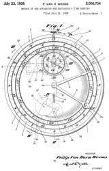
2008734
Method of and apparatus for navigators' time keeping, Weems
Philip Van Horn,1935-07-23 - clockwork includes a
ball & disk
integrator used as a variable speed
transmission for the rate setting stem (31 &33
for both clock mechanisms). This is the "Weems
Second Setting Watch"
Weems
Second Setting Watch Blueprint - This blueprint
may have been drawn based on this patent rather than
being a drawing from a second patent.
The Lindbergh
Hour Angle Watch was based on Weems. "The idea of
simplifying celestial navigation by using Hour Angle and
declination instead of altitude and azimuth was first
suggested by Weems,..." The Lindbergh watch has
hour angle associated with the time, for example 4:00
o'clock = 60 degrees. The bezel rotates and so
that the Equation Of Time (Wiki)
can be applied to get sun time rather than mean
time. The watch can be purchased regulated to
standard time or sidereal time.
Weems Navigational Watch (Smithsonian)
"Star Altitude Curves" (Smithsonian)
a book published by Weems. This may be key in
operating the Pendulum Astrolabe.
|
|
2049096
Drift and ground speed meter, Philip V H
Weems, Henrich
Robert, 1936-07-28, -
|
|
2143042
Method of and apparatus for navigation, Weems
Philip Van Horn, 1939-01-10, - 6
|
|
2233440
Chart and method of construction thereof, Philip
V H Weems, 1941-03-04, -
|
|
2531248
Position finder, Belch
Keith Rogers, Weems
Navigation, 1950-11-21, -
|
|
2946256
Angular bearing instrument and mechanism for angular
adjustment, Tiffany
Carter, Weems
System of Navigation, 1960-07-26, -
|
|
3002278
Method for space navigation, Philip V H
Weems, 1961-10-03, -
|
Also looking for:
Willis
1845860
Navigating instrument, Willis
Edward Jones, 1932-02-16, - all mechanical, ?function
2762123
Navigation system, Oscar T Schultz, Larkin B Scott, Willis
G Wing, Sperry,
1956-09-11, - stabilized platform inertial nav & star
tracker
Healey
Atom Interferometer
2024 The GPS aided munitions used in Ukraine worked for a
month or two then Russian high power jammers (Wiki)
were brought in and these weapons stopped working and it made
more sense to go back to dumb munitions. There's
development on many fronts to get around this problem and Atom
Interferometry is one possible solution. It allows
making a six degree of freedom sensor (3-axis of
accelerometers and 3-axis of gyroscopes) that maybe a thousand
times more sensitive than current sensors.
Sandia LabNews: The
mother of all motion sensors -
ScienceAdvances: High-performance
silicon photonic single-sideband modulators for cold-atom
interferometry -
11545815
Compact laser source with frequency modulators generating
multiple lines, Anthony L. Lentine, Grant Biedermann, Michael
Gehl, Christopher DeRose, Jongmin Lee, Kevin Michael Fortier,
National
Technology and Engineering Solutions of Sandia,
2023-01-03, -
Radio
Omega
This was a system operating in the frequency range
around 10 to 15 kHz. Ships at sea could keep track of
their position in a "lane" defined by the phase of the
signal. System became obsolete with the deployment of GPS.
Bearing
Army field set for getting DF bearings covering the
HF, VHF and UHF frequency ranges. Uses antennas rotating
up to 150 RPM and a CRT display. Will provide a bearing
even with a very short transmission.
38 - 55.4 MHz DF Loop Antenna
This is an H.F. radio receiver with a loop and sense vertical
antenna system designed to determine the bearing to a station.
Non Directional Beacons
These are located on or near airports and send a carrier and
single sideband CW ID in the 200 to 400 kHz range.
Aircraft can tune into the carrier and get an indication of the
bearing to the station.
ARN-83
ARM-93 Test set.
LF Automatic Radio Direction Finder Set; manufactured by
Collins; used in A-37, C-2, UH-1, AH-1T, VH-3A, OH-6, P-3,
S-3, OV-10, U-8F, U-21A
Vietnam era helicopter 100 to 3,000 kHz frequency
coverage direction finding receiver. can use NDB, AM broadcast
stations or other signals in this frequency range.
Viet Nam era. Transmits a programmable ID on a
frequency in the 265 to 535 kHz range and includes a 50 foot
antenna with no part longer than 19 inches. The complete
system is in one back pack. Most likely made for use
with the ARN-89.
Doppler RADAR (Wiki)
Developed for large aircraft (not allowed to fly with
belly up since that would break RADAR beam to ground).
Three or four radar beams would be aimed at the ground and the
Doppler (Wiki)
signals on the beams would be translated into the horizontal and
vertical aircraft position allowing navigation. See Doppler
Nav AN/APN-81)
Ref 1. Investigation of Active Doppler Velocity Sensor 1963 (AD0407250.pdf),
57 pages - for use landing on planets
Ref 2. Air and Space Museum: Kollsman
APN-67 experimental display.
Ref 3. C141 Section 6, Ch 16 Doppler Radar - APN-67 (section_6_16_doppler_radar.pdf)
Ref 4. History
of Doppler Radar Navigation, Walter R. Fried, 1993,
The W.W.II Loran-A system operated around 1.8 MHz was
replaced with the Loran-C system operating with pulsed signals
on 100 kHz. Maybe Loran-B was an idea that never was made
operational? There are a number of "chains" consisting of
3 to 5 stations with all the stations in a chain using the same
Group Repetition Interval (GRI). If a scope is
triggered from a GRI generator the stations is that chain will
appear as pulses with different fixed times on the horizontal
axis while the pulses from stations using other GRI values will
be jumping around. Until GPS this was the most accurate
system for positioning and for time transfer.
2005 - It looks like Loran-C will be used for aviation safety
providing a redundant system to support automatic
landings. Other systems like the Russian or European
equivalent to GPS are not good candidates because a jammer for
GPS would also take them out.
The U.S. LORAN-C system was shut down on 08 Feb 2010.
March 2012 - there is some LORAN-C acitivity in a test phase for
an alternate to GPS for critical timing applications.
YouTube: Taking
a LORAN A fix on 1850 kHz, 2:28 -
Table of Loarn-C
Chain Stations -
Loran Patents
This hand held unit was for use in the Operation
Desert Storm/Shield area by the U.S. military.
This is designed to attach to either a PRC-25 or PRC-77
back pack VHF low band transmitter receiver and report
position via radio. Also receives Loran-D which must be
a temporary system that the military could put in place.
Austron 2100F LORAN-C Frequency Monitor
- for precise Frequency
Austron 2100T LORAN-C Timing
Receiver - for precise time
Austron 2042 LORAN-C Simulator -
Lorchron LORAN-C Timing Receiver LFT-504
- for precise timing
TI 9100 Aircraft Receiver
Sputnik
When Sputnik was launched in 1962 the Doppler signal
was used by scientists at Princeton to determine the orbital
parameters of the satellite. They quickly realized that if
a satellite was to transmit its orbital parameters then a person
on the Earth could determine their position. This was the
basis for the Transit Satellite Navigation System.
Transit
There were only a small number of satellites
transmitting on 150 and 400 MHz. A submarine whose
inertial navigation system had drifted could receive the Transit
pass which took maybe 15 to 30 minutes and then update their
inertial system. This system required a very high quality
= expensive (atomic) clock. was being developed one of the
parameters was to eliminate the need for an expensive clock.
A 120 to 170 MHz eggbeater
antenna would allow reception of the Transit signal on a
vehicle.
"The modulation of the satellite signals was recovered in the
AN/BRN-3 from whichever channel (150 or 400 MHz) was being
received with the best SNR. The modulation provided 6103 bits of
information every 2 min ( 50.85 bits per second) and a beep-time
index every 2 min, decomposed into 156 words of 39 bits."
33 or 39 bits?
MX 4102 Satellite Navigation receiver
by Magnavox
Johns Hopkins Applied Physics Lab Technical Digest January-Marc
1998, Volume 19, Number 1 - Transit
3172108
Method
of navigation, Frank
T McClure, 342/451, 701/469
TRANSIT
navigation system.
3091079
Propulsion
engine with electromagnetic means to produce propellant
acceleration, Kunen
Alfred E, Republic
Aviation Corp, May 28, 1963
Pulsed Plasma thrusters with 14 year life based on Teflon as
fuel and Magneto Hydro Dynamic drive.
3529291
Synchronized sequence detector Claude
W Brown (China Lake, US Navy), Dec 4, 1967,
33 bit Barker Code Receiver (Wiki)
GPS
The GPS system has about 24 satellites in medium
orbits (they are lower than geostationary) orbiting the Earth in
three rings.
They transmit their orbital parameters. By receiving the
signals from four satellites a GPS receiver can figure out where
it is and also the error in its clock. If the receiver is
in a known location only one GPS satellite is needed to know the
time. If more than 4 satellites are received the quality
of the position fix improves. It may be that 1/2 of the
satellites are visible at a time and that's why there are twelve
channel receivers.
In order to test GPS receivers before any satellites
were in orbit, Stanford Telecommunications built a small
number of GPS transmitters. They later made custom chips
for military GPS receivers.
I have heard from a former STI employee that these
receivers were used to debug the large scale ICs STI made
for GPS receivers. In particular channel to channel
timing skew.
AN/URN-502 Canadian Military GPS
This, large by today's standards, GPS receiver was
built using different printed circuit boards for different
functions and an OEM GPS receiver board made in Japan.
PSN-8 GPS receiver
This GPS Timing receiver was designed for military
GPS timing and uses a couple of the Stanford
Telecommunications GPS chips. Needs a down converting
antenna, if you know about the antenna, please let me know.
Garmin GPS III+
This hand held 12 channel GPS unit has a built in
World map and bread crumb trail capability. It can also
average Lat and Lon but NOT altitude, mine is up to 3,051,294
averages today, and can go to 99,999,999. This will take
some time because the readings are one per second. It took
about 35 days to get this far. I would take over 3 years to
run out the counter.
Motorola GPS
Oncore VP
These are 8 channel general purpose OEM receiver
boards that I have in the evaluation version boxes. They
have timing accuracy in the 30 nS area when used in the known
position mode where all the variables are applied to getting a
good 1 Pulse Per Second. Unfortunately they have been
discontinued and there is not a replacement with the same very
comprehensive capability. Synergy is where I
purchased my VP+ units.
Motorola M12+ Timing
If the M12 has the same Motorola binary format
differential correction output that is in the VP series (I
most probably does) then it should be possible to place the
antenna at a know location and using some math save the
corrections for each satellite. Then switch to rover
mode and have those same corrections fed back into the
receiver to correct it. This is covered in a CSI patent, but they
don't offer it in this format. Note this is much
different than "poor man's differential correction" since
actual corrections are being made for each satellite, not just
a Lat and Lon position correction. The key limitation is
the time from obtaining the differential correction and the
time that most of the satellites set. Note that GPS sats
have a nominal 12 hour orbit so maybe 4 hours overhead.
- follow on after the Trimpacks, is a large hand held
unit.
p/n 14992-20 & 16768-20 AN/PSN-10 SLGR, Came out just in
time for Desert Storm & Desert Shield, gulf wars.
Since these were L1 CA code receivers L1 was turned off for the
Gulf wars, Desert Storm and Desert Shield. Many of these
can average Lat, Lon and altitude
GSM-336 GPS Test Set
(@BPB
Surplus) Anyone have info on what this set does?
Manuals
TM 11-4920-297-12 Opertion and Maintenance Intermediate
for
Navigation Set Test AN/GSM-336(V)1, 685-7539-001, (NSN
6625-01-319-7118),
Navigation Test Set AN/GSM-336(V)2, 685-7540-001,
(6625-01-294-1941),
Navigation Test Set AN/GSM-336(V)3, 685-7541-001,
(6625-01-317-4851)
{TO 33D7-71-51-1; NAVAIR 16-30GSM336-1}
TM 11-4920-297-12P Illustrated Parts Breakdown for
Navigation Test Set AN/GSM- (NSN 6625-01-319-7118),
685-7539-001,
Navigation Test Set AN/GSM-336(V)2, (6625-01-294-1941),
685-7540-001,
Navigation Test Set AN/GSM-336(V)4, (6625-01-347-1757),
685-7540-020,
Navigation Test Set AN/GSM-336(V)3, (6625-01-317-4851),
685-7541-001
{TO 33D7-71-51-4; NAVAIR 16-30GSM336-2}
GPS Denied Navigation
A few months after a new GPS guided weapon system was
introduced into the Ukraine war it would no longer work.
The main cause of the failure was the Russian jammer R-330Zh
Zhitel (Wiki).
Flight
Radar 24 has a map showing where GPS is being jammed based
on ADS-B data.
There is now a search for new navigation methods that work
without GPS. I think inertial navigation will be part of
all of these alternative systems, but it has the drift problem
that will need to be solved with a method other than GPS.
Honeywell is looking into: Vision Aided, Celestial Aided RADAR Aided
& Magnetic Anomaly Aided solutions (Honeywell).
They make a lot of INS systems.
A possible way to navigate would be to use LORAN-C (Wiki).
The signal at 100 kHz is extremely hard to jam. A
temporary system could be deployed in a manner similar to the Light Weight Beacon.
20090177398
Angles only navigation system, Mikhail Belenkii, Donald Bruns,
Timothy Brinkley, George Kaplan, Trex Enterprises, 2009-07-09, -
IMU plus Celestial nav - "Future aircraft will operate for long
durations (from tens of minutes to several hours) at SuperSonic
speeds (Mach 3 to Mach 5) and altitudes of 70,000 feet above
ground level. There exists a strong possibility that such
vehicles will not be able to rely upon GPS for the entire flight
path. In some situations GPS may not be available." Cited
by 38 patents
8072581
Laser range finding system using variable field of illumination
flash lidar, Arlen E. Breiholz, Rockwell Collins, 2011-12-06, -
"The present invention relates generally to measurement of
distance to visual landmarks for applications including
navigation and mapping, and more particularly navigation and
mapping in a Global Positioning System (GPS) denied
environment."
8315794
Method and system for GPS-denied navigation of unmanned aerial
vehicles, Dennis W. Strelow, Alan B. Touchberry, Honeywell,
2012-11-20, - requires one UAV with good GPS.
10184799
Systems and methods for targeting objects of interest in denied
GPS environments, Richard B. Guthrie, Boeing, 2019-01-22, - LRF
similar to the Vector IV sights known landmarks
and target.
11675026
Self-locating compass, Frederick
Vosburgh, Archaius,
(Archaus.net)
2023-06-13, - cites
34 patents - IMU + a Lorentz force (Wiki)
detector operating on the Earth's magnetic field inside a Faraday
Cage (Wiki).
WO2021146120
Magnetic velocity and position sensors, Frederick
Vosburgh, Archaius,
2021-07-22, -
20240060779
GPS-denied geolocation, Dirk B. Warnaar, David H. Johnson,
Applied Research Associates, 2024-02-22, -
Y Combinator: Theseus:
GPS Denied Navigation for Drones - sensor is IMU and high
resolution still camera assembly. Processor is Raspberry Pi
with Google Earth image on SD card. I'm guessing the map is
limited in area to match expected UAV flight path to allow more
resolution. Amazon has many 9-axis IMUs.
See reddit: How
to do IMU and camera "sensor fusion" tracking? -
ANELLO
Photonics.com - GNSS
INS/ATAK Kit (GPS-denied environments) - based on their FO
gyroscope
10731988
System architecture for integrated photonics optical gyroscopes,
Mario Paniccia, Qing Tan, Anello
Photonics (Anello Photonics.com),
2020-08-04, -
Miscellaneous
1069842
Device for recording the paths of ships, Hermann
Anschuetz-Kaempfe, 1913-08-12, - an integrating ball is
driven in two orthogonal axis, speed input from propeller,
direction from magnetic or gyro compass.
References
NDRC
Div 13, Vol 2B, Electronic Navigation Systems 1946
Declassified from SECRET Sep 23, 1960. - Starting with 2. Beacons
& Interrogators, 3. Oboe, 4. Shoran, 5. Micro-H ... 24.
AN/APN-34 Short-Range Approach System, 29. AN/APA-44
Ground-Position Indicator (GPI),
NDRC Div 14, Vol 1, RADAR: Summary
Report and HARP Project, 1946 - Declassified from SECRET Sep
26, 1960.
NavList:
- blog started 2010
ReedNaqvigation.com
-
Defense Technical Information Center (DTIC): AD-785 549, History of
U.S. Army Engineer Topographic Labratories (1920 to 1970), John
T. Penningron, Nov 1973 (AD0785549.pdf)
- Surveying page 63 (pdf pg 79), Astronomical Position
Finding (pg 66 (pdg pg 83) See Pendulum Astrolabe weighs 34
pounds; The David White 60 deg model replaced the 20 inch
Transit. The AF developed a 24" FL Zenith camera in 1941,
but it weighed 180 pounds, so they tried a 12" FL Zenith
camera. The one made by David W. Mann was selected (weight
30 pounds).
1509899
Stop-watch mechanism, David
W Mann, 1924-09-30, - short intervals, more precision
2206817
Precision spirit level, David
W Mann, LS
Starrett Co, 1940-07-02, - includes adjustment with
graduated dial.
ASPRS
Journal Sep 1950 - Research Committee, 19 pages - David W.
Mann helped design the Fairchild Precision Camera Calibrator
- 33 Collimators positioned at known angles; The Mann
Comparator which measures distance up to 12 inches with micron
increments.; K-40, K-37, Ballistic Cameras for tracking aircraft
in the sky, Type N-9 Gun camera, Distributed Optical Axis Camera,
Projection Printer, 35mm Recording Camera, Ortho Camera,
(1967 - 1978, ADA088805.pdf)
The
Military Lensatic Compass -
Which
Way North, Part IV - The Military Lensatic Compass -
History
Revealed! Origins Of The Army Lensatic Compass -
MIL-PRF-1043N
Performance Specification, Compass, Magnetic, Unmounted, Lensatic,
Luminous, 5 Degree and 20 Mil Graduations, With Carrying Case -
"This specification covers an induction-damped, lensatic,
unmounted, magnetic compass, with 5 degree and 20 mil graduations,
for individual use during day and nighttime." This 1998 spec
references the 1995 Magnetic model, so I expect there's a revised
spec that uses the current magnetic model. "... worldwide
battlefield deployment"
Links
Surveying Patents -
GPS patents
Army
Space
Reference
Text - 7-26
Characteristics
of
an Ideal Pos/Nav System -
" - same
thing
at
FAS with proper formatting
Navigation mailing list -
American Society for
Photogrammetry & Remote Sensing - Grids & Datums
-
Back to Brooke's Products for Sale, Astronomy, CCD
Astronomy, Sundials, Surveying, Time
& Frequency, Military
Information, Home page
page created: 20 Oct 2001.