Crystal Impedance Meters
© Brooke Clarke 2016Description of Sanders 150C
Operation
Controls & Indicators
Options
Quick Setup
Modes
Photos
Patents
Related
References
Links
Background
Electronic quartz crystals (Crystals, Wiki) are used as frequency determining elements, usually in an oscillator, but also in filters. In both cases it's important to have good characterization data for the design process. Because of their high Q (Wiki) special test equipment is needed to characterize quartz crystals. The goal is to have good values for the Crystal Equivalent Circuit.
Crystal control of radios became a major project in W.W. II (Video: Crystals Go To War 41:28 - note lack of safety precautions). To go along with the high volume manufacture of the crystals a family of Crystal Impedance (CI) Meters was developed based on vacuum tube (Wiki) technology.
Later solid state versions were developed and finally units that had remote control capability for automated testing became popular.
Although not designed for crystal testing, some general purpose test equipment and be used to determine crystal equivalent circuit parameters, such as the HP/Agilent 4395A analyzer.
A Crystal Activity Meter is used to see of a crystal will work in an oscillator, but not to determine any of it's design parameters.
The vast majority of crystals are used for specific purposes and these have standardized operating frequencies (Wiki, My list of Crystal_Freq.pdf with mathematical factors).
Crystal Radios (Wiki) use a different type of crystal as a radio frequency detector and are not related to crystal impedance.
Crystal Balls and Crystal Healing are quack ideas.
The common 32,768 Hz watch crystal has an extremely high Q and so is very difficult to characterize. They are used in Quartz clocks, watches and many electronic items where an internal clock and/or calendar is desired.
Description of Sanders 150 B & C
Difference between B and C versions amounts to 9 hardware changes, no firmware changes so the 150B and 105C are identical in terms of operation. If you have a parts location diagram of either or both of the printed circuit boards please let me know (the diagrams in the on line 150C manual are unreadable).
Crystal Resonance Modes
There are two resonance modes, series and parallel. Most applications use the crystal in parallel resonance where there's a capacitance in parallel with the crystal and the value of that capacitance may be adjustable in order to tweak the oscillation frequency to be the desired value. In series mode there is no adjustment. Series mode is sometimes used in precision oscillators where the variability of the parallel capacitor would degrade the accuracy. So the crystal impedance meter needs to have a way to supply the needed parallel capacitance.
Saunders model 140 or 150 CI meters made after Sep 1983 have an input protection transformer between J3-8 and J3-9 external frequency standard input to protect IC-IB5 from being smoked if the external standard has any voltage on it's ground side.
Test Fixtures
Crystals do not have coaxial connectors, rather they typically have wires or pins. So they need some type of test fixture both to make electrical connection and to supply the needed parallel capacitance. In the case of impedance characterization where the crystal is connected in series between a signal source and a detector the impedance of the test system should be IEC specified value of 12.5 Ohms rather than the common 50 Ohms used for most test equipment.
Designed to test crystals in the 1 to 60 MHz frequency range. This meter uses a digital display for crystal frequency or parallel capacitance (and maybe other parameters) as well as for error messages.
Other Models
The 100 & 110 are analog CI meters for 1 to 60 MHz crystals.
The 140 is for 8 to 1,000 kHz crystals.
The model 200 is for 50 to 250 MHz crystals.
Option 003 - 005 is a keypad that can be used with digital CI meters.
The Saunders 105C manual (pdf page 114, bottom of page 2 of Appendix B) has a discussion of the IEC 12.5 Ohm test fixture. One effect is to degrade the Q, but that could be corrected knowing the crystal equivalent circuit. In order to get more accurate results with the 150C compared with the IEC test fixture the power set test resistor should be either 3 or 8 Ohms when the crystal resistance is below 15 Ohms, see pdf page 117 for details. Appendix was made to answer questions about correlation between the 150C and measurements made using the IEC test fixture.
Operation
See the tutorial video linked below for basic operation of the Saunders 150 CI meter. There are many additional features as described in the 150C manual, but it's going to take some time to figure out which of those work on this 150B.
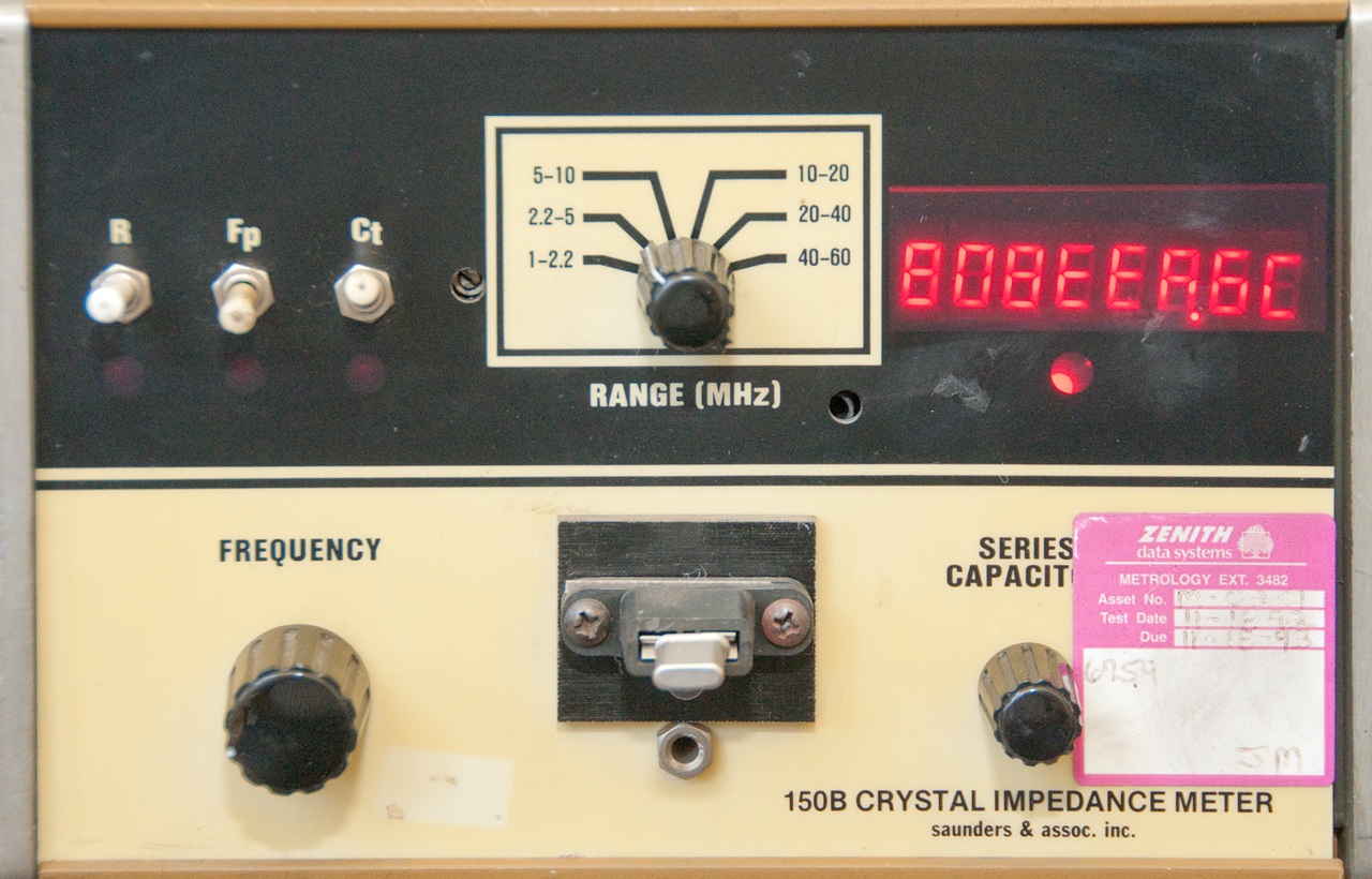
Pressing the power level control in the hole just to the left of the range switch lights all three LEDs under the range switch and displays the power level in uW: 1943.25
Pressing F & C at the same time gives the motional capacitance: 00.018886 (pF) or after mentally moving decimal to the right 3 places 18.886 nF. The series motional inductance resonates with this capacitor at 10 MHz.
If L1 = 1/[C1 * (2 * PI * F)2] then L1 = 0.013412 H
Xl = 2 * PI * F * L= 842713.9j Ohms
Q = Xl/R = 108040
Pressing all three switches (R + Fp + Ct) at the same time displays the mode: C.C.C.C.C.C.C.F
A few of the modes show up in the table in the 150C manual on pdf page 101 (bottom of page 1-3 of Misc Info June 1983). The mode interacts with the switches to control the display.
The last hex character F in this case displays the mode number 0 - 9, A, B, C, D, E or F.
Pressing R & F at the same time displays the reference frequency: in this case shows 10000007 Hz, i.e. 10 MHz so Option 002 (analog frequency output) probably is installed. The output voltage is relative to the reference frequency. So a 0 to 10 VDC meter (5 VDC is zero frequency offset) would allow someone adjusting crystal frequency so easily get to the desired frequency (much easier than reading a digital display). To use this option the mode needs to be set to 4. Mode 5 sets the DC output for +500ppm. Set to mode 0 and the output will be for -500ppm. Now set to mode 2 or 3 and use the analog output.
More complicated than this short summary. Only modes 0 through 3 are mentioned. So what is mode "F"?
0 normal operation
1 reference measurements
2 normal operation (option 2 analog freq out)
3 reference measurements (option 2 analog freq out)
4 Analog Frequency Output, if present
After leaving the unit running for awhile (10 minutes?) the display is all zeros and the LED under the display is dim. Switched make no difference. Rotating the range switch a couple of ranges either way causes a hex error message: EEA6.C After awhile (10 min?) the display is back showing Fs. After 30 minutes the display is still showing Fs.
Controls & Indicators
Front Panel
Function Toggle Switches R, F & C
Note the F switch has three positions locked up, center and momentary down. The up and down positions are Fp and the center is Fs.
So for the table I'll only show center and down positions.
The R and Ct switches are two position switches with up and down positions.
Display
R
F
C
Fs (series)
Up
center
Up
CL
Up
center
Dn
Fp (w/load Cap)
Up
up or down
Up
Cmotional Up
up or down Dn
Rs
Dn
center
Up
CL (error)
Dn
center
Dn
Fp (error)
Dn
up or down Up
Mode
Dn
up or down Dn
(error) when a non valid combination of switches is pressed the LED below the wrong switch flashes.
Range Switch
Frequency Knob
J7 Crystal Test Socket
Capacity Knob
Mode Selection & Display Switch
Power Level control
7-Segment Display
Crystal Activity LED
Mode LEDs
Rear Panel
IEEE-488
This instrument was made about the same time as IEEE-488 was announced by HP, so has a crude implementation.
Remote
Uses a nibble (half a byte = 4 bit) interface.
My best guess.
J3 Remote Interface pin out
Pin
Function
1
Not Remote
2
Ground
3
Control0
4
Control or Data
5
Data2
6
Data3
7
Control2
8
Ext Frequency Ref In
9
" shield
10
Data1
11
Data0
12
Analog Freq Out
13
Control1
14
Ground?
IEC AC power input
Fuse
Trip Pot
Not sure. It's not a frequency trim for the internal crystal oscillator - that's done with a trim cap.
What is it for?
Internal
SD3 is an internal 6-position DIP switch, What does it do? (guess option selection)
Select one resistor to match external reference frequency.
Where are these resistors? let me know.
Designation
Frequency
RB38
10 MHz
RB39
5 MHz
RB40
1 MHz
RB41
500 kHz
RB42
100 kHz
RB43
50 kHz
Options
1. the keyboard includes a BNCf external reference frequency input cable.
Option
Description
1
IEEE 488 Control and printer port
2
3
Keypad1
4
Low Power
5
Keypad1 w/more capability in Modes: 8, 9, A or B
Quick Setup
1 Set band switch to desired frequency range.
2 Insert a non-reactive setup resistor of the same value as the crystal resistance into the test socket. (This differs from the original manual that used a 50 Ohm resistor)
3 Adjust power level to desired power.
4 Adjust tuning knob to the crystal series frequency.
5 Remove setup resistor from the test socket.
6 Adjust the Ct for the desired load capacitance if necessary.
7 Insert crystal into the test socket. The output frequency is the crystal series resonant frequency. The crystal resistance can be determined by depressing the R switch.
Note: If the crystal resistance and/or frequency is not known, place the crystal in the socket and tune for minimum resistance by holding down the R switch and watching the reading. Note the crystal frequency reported (use this frequency for step 4 above). Substitute the appropriate resistor. Proceed starting with step 2 above.
Mode Switch
Mode
Result / Comment
0
Display Frequency. Analog Output not supported.
Manual Section: Operation, Page 1-3.
1
Not supported
Manual Section: Operation, Page 1-3.
2
Display Frequency. Analog Output not supported.
Manual Section: Operation, Page 1-3.
3
Not supported.
Manual Section: Operation, Page 1-3.
4
Not supported.
Manual Section: Operation, Page 3-1.
5
Not supported.
Manual Section: Operation, Page 3-1.
6
Engineering Measurement Mode.
Manual Section: Options 003, 005 Pages 2-1, 2-2, 4-6 thru 4-8.
7
Inspection QC Mode/Go No Go.
Manual Section: Options 003, 005 Pages 2-2, 4-9 thru 4-17.
8
Display Frequency. Analog Output not supported. (similar to 0) Keyboard1
Manual Section: Options 003, 005 Pages 2-1, 4-6.
9
Display ppm from Ref Freq. Analog Output not supported. (similar to 1) Keyboard1
Manual Section: Options 003, 005 Pages 2-1, 4-6.
A
Display Frequency. Analog Output not supported. (similar to 2) Keyboard1
Manual Section: Options 003, 005 Pages 2-1, 4-6.
B
Display ppm from Ref Freq. Analog Output not supported. (similar to 3) Keyboard1
Manual Section: Options 003, 005 Pages 2-1, 4-6.C
Engineering Measurement Mode Printout.
Manual Section: Option 006 Pages 2-1, 4-1 thru 4-3.
D
Inspection QC Mode/Go No Go Printout.
Manual Section: Option 006 Pages 2-2, 4-3 thru 4-7.
E
Not supported. F
Not supported. (strange I received meter in this mode.) 1. The Reference frequency can be entered from the keyboard.
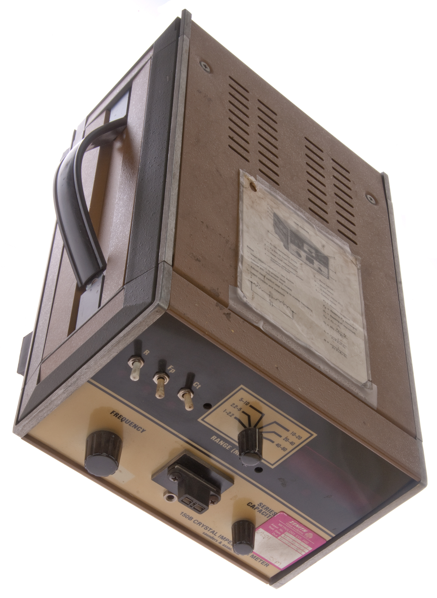
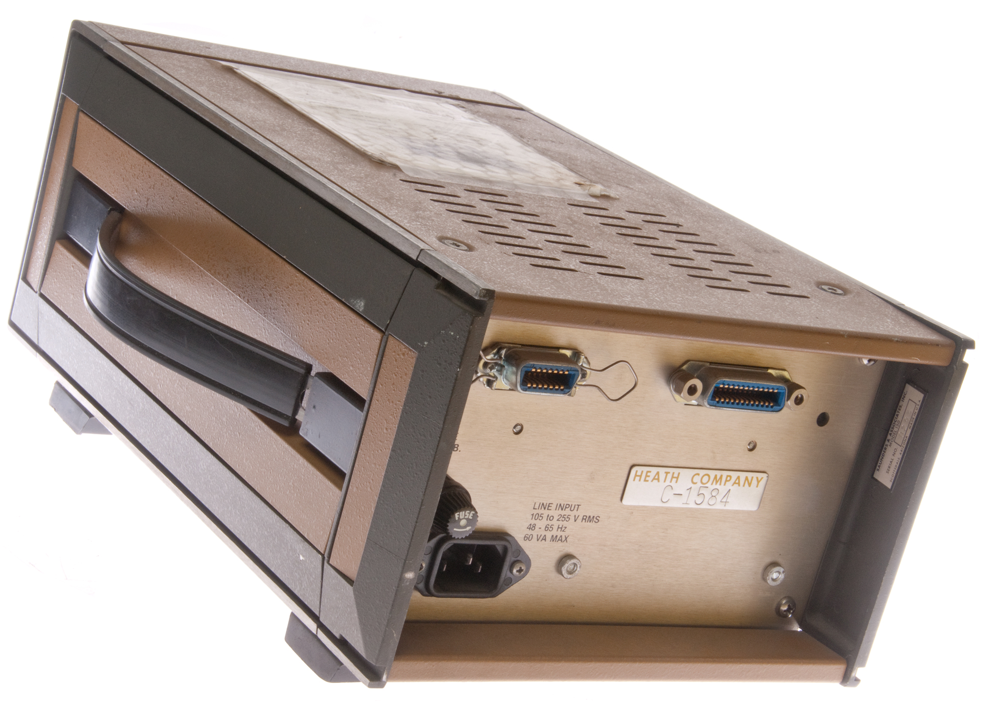
Photos Saunders 150B Crystal Impedance
Meter
Fig 1
Fig 2 Options to allow for remote keyboard and the IEEE 488 option.
This looks similar to the back panel of the 150C.
To the right of the IEEE-488 connector is a hole, and
there's an adjustment pot behind it.
There is a Heath Company property label. This CI meter
may have been used to characterize the 3.6 Mhz crystal
used in the Heathkit GC1000 clock. That crystal was disciplined by WWV to be on frequency.
Fig 3 Meter on with 10 MHz crystal.
C was already set to 20 pF.
The crystal is 10 MHz and the range is 2.2 - 5.
I was able to eliminate the error hex characters on the
right of the display, i.e. see a freq near 10 MHz, but not
able to minimize the Resistance, but after switching
to the 5 - 10 MHz range get:
R= 7.8 Ohms
Fp= 10000000 Hz after adjusting Cp to 23.47 pF*
Fs = 9995978.9 Hz
For a Jameco SKU: 14381 crystal
A small trimmer capacitor with a nominal 20 pF would
work to bring this crystal to 10 MHz (Fp)
Fig 4 Pressing both F & C to get motional capacitance
Fig 5 mystery mode? Happened just before taking Fig 6
It came and went for a reason unknown (no one touched box).
Fig 6 Range set to 10-20 (was 5 - 10) Xtal = 10 Mhz
On 5-10 range Fs = 9995978.9 Hz delta 1 Hz
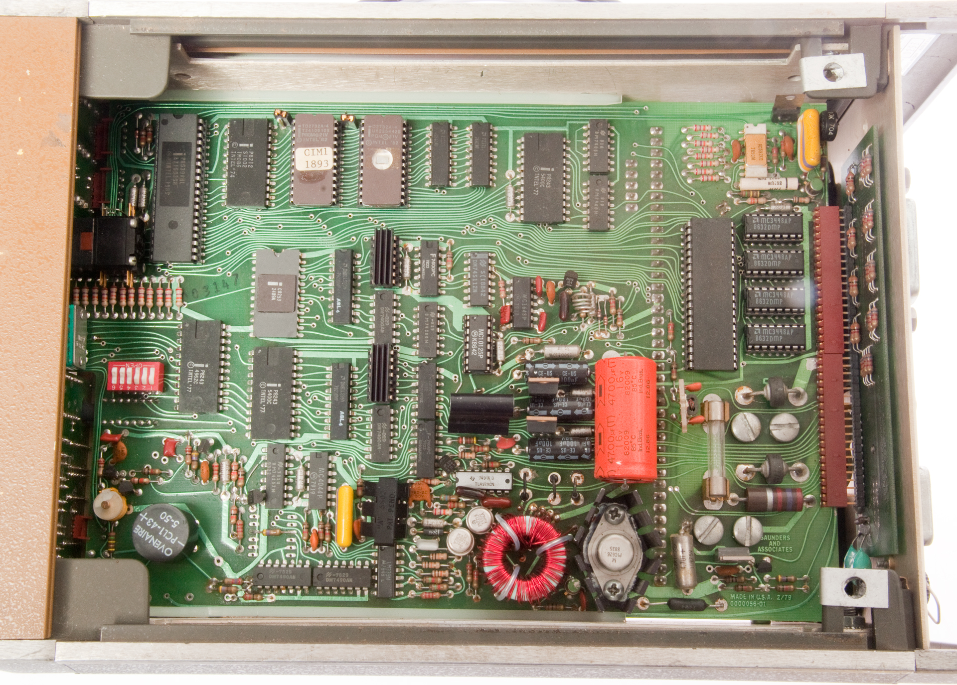
Fig 7 Inside Bottom Analog Measure PCB
Fig 8 Inside Top Control Logic PCB
The white variable cap near the Ovenair crystal is the
internal frequency standard adjustment.
See Chapert 6 Calibration
Fig 9 Russian 5 MHz crystal PK207CP, 5000K, 1284, 206
R = 4.8 Ohms
Fl = 5002706.8 Hz
Fs= 4999977.0 Hz
Cm=0.021600 pF
L1 = 1/[C1 * (2 * PI * F)2] then L1 = 0.046908 H
Xl = 2 * PI * F * L= 1.474E6
Q = Xl/r = 307,013 (high but not over a million)


Patents
2919398
Crystal impedance meter, Guttwein Gunter K, Sec of US Army, Dec 29, 1959, 324/727, 324/708, 331/160, 324/762.1, 324/754.28 - for > 100 MHz crystals, tubes
Ref: Crystal Impedance Meters, Electronics, May 1953.2931976 Resonator mode test set, Gougoulis George H, US Sec of Army , Apr 5, 1960, 324/727, 324/619 - harmonics, tubes
3832631 Method for measuring parameters of quartz crystal units and fixture for carrying out the same, Kobayashi S, Koga I, Okamoto I, Kokusai Denshin Denwa Co Ltd, 324/727, 324/76.51, 324/619, 324/652 - a special fixture that allows the probe from an HP 8405A vector voltmeter to probe the crystal terminals and plot impedance.
3840804 Crystal frequency monitor, F Sauerland, Oct 8, 1974, 324/727, 324/76.52, 324/650, 324/709 - based on series mode zero phase shift measurement
4001675 Test set for measuring impedance and power dissipation of a crystal, John R. Veleber, R F L Industries, Inc., Jan 4, 1977, 324/727, 324/705, 324/708, 324/621, 324/601
4447782 Apparatus for automatic measurement of equivalent circuit parameters of piezoelectric resonators, John P. Rutkoski, May 8, 1984, 24/727, 324/76.49, 324/76.41, 324/622, 324/650, 331/2, 324/619
Related
HP 4395A Network/Spectrum/Impedance Analyzer - Crystal Oscillators running in equipment
Victor VC2000 Crystal & Frequency Meter - a frequency counter that also reads crystal frequency
Xam Crystal Activity Meter
Xec Crystal Unit Equivalent Circuit
Xtal Electronic Crystals
Xtal1800 Crystal Radio 1800? & Brooke Clarke #1
Xtc Crystal Temperature compensation Patents
References
YouTube: Quartz crystal motional parameters, and how to measure them - Instructional video on the 150 starts at 4m37s.
Broadcast Engineers' Journal, Vol 13, No. 5, May 1946 -pg 6 85. Problems Associated with the Standardization of Quartz-Crystal Units for Military Equipment - Charles J. Miller, Jr.
Load resonant measurements of quartz crystals, Saunders & Associates Inc., Scottsdale, AZ, Frequency Control, 1991
Direct Impedance Method for Load Resonant Measurement of Crystal, Lee & Chan, Kolinker Ind Eq Ltd, Aug 1999 - compared to HP E5100 Network Analyzer (CI Analyzer).
Links
PRC68, Alphanumeric Index of Web pages, Contact, Products for Sale
Page Created 15 July 2016