An Instantaneous Direct-reading Radiogoniometer

By R. A. WATSON WATT, B.Sc. (Eng.), and J. F. HERD, Associate Members.
             [Communicated by permission of the Radio Research Board.]
(Paper first received 6th January, and in final form 12th February, 1926; read before the WIRELESS SECTION 3rd March, 1926.)

Source for this web page is: Scottish Science Hall of Fame, An instantaneous direct-reading radiogoniometer.
Reformatted by Brooke Clarke 2020 for this web page.

Table of Contents

Summary
1. Introduction
2. Description
3. Properties
4. Typical Observations on Atmospherics
5. The Beacon Problem
6. Discussion before the Wireless Section, 3 March, 1926
7. Related Patents
Related Web Pages
References
Links

Summary

The paper describes a visual direct-reading radiogoniometer capable of indicating the apparent azimuth of arrival of wave-trains the durations of which need not exceed 0·001 sec. The special properties of the device, which comprises essentially a combination of directional aerials with a cathode-ray oscillograph, are discussed. Amongst these properties is that of giving simultaneous bearings on two or more stations transmitting simultaneously on the same wave-length. A typical installation is described, and specimens of observations on the distribution in azimuth of received atmospheric disturbances are shown. A possible solution of the problem of navigational beacons is suggested.
                    _____________________

1. Introduction

The defects and limitations of radiotelegraphic direction-finders of the types in commercial use have now been clearly realized and frequently enumerated.  Some of these defects are inherent in the use of the simple vertical loop as a receiving element, since multipleray effects are then liable to produce errors in the apparent azimuths read by the instrument. Other defects are peculiar to the means adopted for determining this apparent azimuth.  The work on which the authors are engaged, the investigation of the nature and origin of atmospherics, is peculiarly suited to call attention to these defects.  The directional side of the investigation is concerned with the determination of the place of origin of electromagnetic disturbances which are arriving in very rapid succession from very diverse azimuths, from distances ranging from a few miles up to or exceeding the earth's semi-circumference, with peak field strengths varying from several volts per metre down to the lowest measurable values, with durations varying widely about a mean of the order of a few thousandths of a second, and of diverse forms.

The standard forms of radiogoniometer have been applied to the study of this heterogeneous distribution, and although the results of such applications have been very illuminating, one can only express surprise that they should have yielded data capable of interpretation.  The rotating-loop method—embracing the Marconi-Bellini-Tosi-Artom radiogoniometer (Wiki) with its ingenious method of rotating a large “ effective loop ” by means of a small search coil, the single-coil direction-finder, and the Robinson crossed-coil instrument—is not well suited for work on any signal other than a simple wavetrain sustained or repeated over a period of the order of several seconds, from a sensibly stationary source, and free from interferent signals capable of producing, in the loop, electromotive forces amounting to so little as ½ of 1 per cent of the maximum electromotive force from the desired signal. The inertia of the moving elements prevents the taking of bearings on brief wave-trains, or on wave-trains the apparent azimuth of which is varying at a rate exceeding a limit which may be generously estimated at 1° per sec. The form of the cosine polar curve is such that only the position of minimum electromotive force can be used for accurate determinations, and ensures that any interferent train capable of producing E.M.F.'s of the same order of magnitude will effectively mask this minimum when the apparent azimuths of desired and undesired signals differ by 60° or more, whilst much weaker signals from azimuths within 20° of the minimum will also mask the latter.

Thus it is certain that at the best this type of direction-finder will, when applied to the study of atmospherics, merely indicate the mean apparent directions of arrival of the predominant streams of atmospherics, and that there is always a high probability that two physically independent streams will be merged into one statistically true but physically fictitious stream in the indications of the instrument., When to these defects we add the extreme crudeness of the discrimination in amplitude afforded by aural reception, or by any simple recording system, it is abundantly clear that there is a pressing need for radical changes in direction-finding apparatus in general, and in that used in the study of atmospherics in particular.  The ideal radiogoniometer would record the true azimuth of arrival, i.e. the horizontal projection of the direction of propagation at the point of incidence on the receiver, of any desired signal, of whatever form or magnitude, and however brief its duration, and would at the same time record at least one fundamental parameter determined by peak field strength or one of its derivatives. The indication should be independent of the presence of simultaneously incident signals of any form or distribution.  The purpose of the present paper is not to describe the ideal instrument, but to describe a device which is believed to be a much closer approximation to that ideal than were its predecessors.

2. Description

The general principle of the device is almost too simple to require detailed notice. Consider, for example, two loop aerials, A and B, identical in every respect, with their planes vertical and at right angles to one another. Then a vertical wave-front, in which the maximum vertical electric force is E, and the ray direction of which makes an angle ψ with the plane of loop A, will produce E.M.F.'s proportional to E cos ψ and E sin ψ in A and B respectively. The E.M.F.'s across the identical capacities CA and CB will have the same ratio. Let the two perpendicular and identical deflector systems, ns and ew, of a cathode-ray oscillograph be connected across CA and CB respectively. Assuming for the moment that the deflectors have their centre points in a plane perpendicular to the axis of the undeflected beam, the two fields will recombine to produce a resultant field of strength proportional to E, and making an angle ψ with the axis of deflection corresponding to plates ns. Thus the fluorescent spot traces on the screen a line the length of which is linearly related, through the intervention of simple circuital constants, to the E.M.F. which would be induced in a loop, similar to loop A, with its plane in the ray direction; this E.M.F. in its turn is proportional to the rate of change of electric force in the wave-front, and is related to that rate of change by the well-known equation of the loop antenna.  Further, the angle which this fluorescent line makes with the reference axis ns is equal to the angle between the ray direction and the plane of loop A.  Similar considerations apply in the case of magnetic deflection, but in general it is desirable to operate by electrostatic deflection, since the impedances involved are usually of an order which enables greater sensitivity to be attained by this method.  If sensitivity comparable with that of the standard direction-finding installations of commerce be required, then in general the component electromotive forces induced in the two loop aerials will require amplification before being applied to produce deflecting fields in the oscillograph system. It will be shown later that this amplification can be successfully employed.  In passing from the ideal case to the actual apparatus, employing the type of oscillograph mentioned, several minor points are to be noted. In the first instance it should be observed that in the instrument used the disposition of the deflector systems is as in Fig. 1. The change of field during the time occupied by an electron in traversing the paths between either pair of deflectors, or from the one system to the other, may be neglected, since the total path xy is executed in 0·0015 micro-second, corresponding to a phase angle of ½° at a frequency of 1 million per second, so that no error is introduced from this cause, even at the shortest commercial wave-length now in use. For still higher frequencies the re-design of the oscillograph to reduce this time-lag to negligibility does not appear to present serious difficulty.  A second point arising from the same feature of the tube design is that whilst the angular deflection produced by unit E.M.F. in the two systems is the same, the plates producing horizontal deflection are nearer the screen than are those producing vertical deflection, the distance ratio being 1·08. There is consequently an angular error which varies with azimuth, reaching a maximum of 2¼° around the 45° points. As this source of error is independent of amplitude and frequency, a permanent scale correction is readily applied when necessary. Again the error is not inherent in the system, but is incidental to the particular instrument used. In any case it can be compensated by a method to be mentioned later.  In cases, such as the study of atmospherics, in which there is no possibility of even a rough check on the faithfulness of the indications, it is desirable to eliminate even remote possibilities of error. For this reason the installation at Ditton Park, to be described, is by no means the simplest or cheapest that can he realized within the scope of the general principle of making an ionic beam the self-setting moving element of the goniometer. It is, however, based on circuits which most completely satisfy the requirements of symmetry and freedom from risk of unequal amplification of the component electromotive forces.  The circuit of this typical installation is represented in Fig. 2. The receptive system comprises two loops in two vertical planes intersecting at right angles along a line bisecting the horizontal sides of each loop. To ensure freedom from “antenna effect” or “vertical,” the mid-points of these horizontal sides are all connected to earth, as is also the anode of the oscillograph. The tuning devices—loading inductances if required, and tuning condensers—are split and arranged symmetrically on either side of the central earth lead. There are consequently, in each main loop, two tuned half-loops, the tuning of each half being nearly independent of the tuning of the other. Carrying still further the provision for complete symmetry, special oscillographs have been obtained in which each deflecting plate is separately terminalled. It will be noted that in the standard pattern of oscillograph two of the plates are joined directly together and to the anode, whilst the other two, one of each pair, are joined to the anode through external resistive paths, so that complete symmetry is not attainable with this form of tube. 

[NLS note: a graphic appears here – see image of page]
FIG. 1.—Deflecting plates of cathode-ray oscillograph.

In the case of strong signals the oscillograph deflecting-plates may be connected directly across the tuning condensers as shown in. Fig. 2. For weaker signals the general scheme of single-stage or multiple-stage amplification is illustrated in Fig. 3. Since the load impedance of the oscillograph, with its plate-to-plate capacity of about 10 µµF and its gaseous conduction path of about 2 megohms, is high, the conditions are especially suitable for “voltage amplification” by a resistance-capacity amplifier employing triodes of high voltage factor.  It will be seen from Fig. 3 that symmetry is maintained by using a circuit of the so-called “push-pull” type, in which, (considering only one stage), the filaments are connected to the central earth lead, whilst the grids are each connected to the high-potential sides of the tuning condensers in the half-loops. The oscillograph deflecting plates are joined through coupling condensers to points on the high resistances included in the plate circuits.

[NLS note: a graphic appears here – see image of page]
FIG. 2.– General arrangement of cathode-ray direction-finder.

In the actual installation under description, the loops are supported on a mast system comprising a central wood lattice mast 200 ft. high, and four wood box masts 150 ft. high, at the corners of a square of 1 200 ft. diagonal. Each loop comprises five turns, which can be grouped in series or parallel, each turn measuring 1200 ft. horizontally by some 150 ft. deep, the area-turns in the series grouping being thus about 8·4 × 104 m2 (about 20 acres). The inductance of the series arrangement is 19 mH, and the effective resistance at 10 kilocycles is 200 ohms. Each unit of the tuning system, as used for atmospheric observations at about 10 kilocycles, comprises a coil of 136 mH and an air and mica condenser assembly with a maximum capacity of 0·006 µF. The arrangement of these units will be referred to later.

Fig 3
FIG. 3.– Details of circuits.

The amplifiers are based on the use of the D.E. 5B triode, and with anode resistances (wire wound) of 105 ohms, and plate circuit voltage 300, give a voltage magnification of 15 per stage. The first anode resistance in each side is tapped approximately in thirds, so that the available voltage magnifications are 5, 10, 15, 75, 150 and 225.  The oscillograph has a deflectional sensitivity of 1 mm per volt, so that the sensitivities of the combination of amplifier and oscillograph are 1 mm for 200, 100, 67, 13, 7, and 4 millivolts respectively on grid. Full-scale deflection, reaching the outer edge of the oscillograph screen, amounts to 50 mm, the angular scale value then being 0·87 mm per degree of angle. So far as reading goes, therefore, accuracies of 1° can be attained en any deflection exceeding half scale.  The two special features of this installation are the precautions taken to ensure symmetry, and the large areas of loop used. This latter feature is part of a general policy which has guided all our quantitative work on atmospherics, namely that the antenna system should be of such dimensions as to allow measurements to be made with a minimum of amplification. It is a general experience that quantitative uncertainties increase rapidly as amplification is increased, and for fundamental work the more antenna and the less amplifier the better. It must not be thought, however, that acres of antennæ are essential to the system, nor that the somewhat uneconomical duplication of triodes, giving only a doubling of amplification, in the push-pull system is inevitable. The use of loops the individual turns of which have an area of 30 m2, with one pair of vertical sides coincident, in combination with normal amplifiers and the standard form of cathode-ray oscillograph, has already been shown to be practicable, and further wide modifications should result from systematic development work, which has not been required for work on atmospherics but is desirable for the production of a compact visual direction-finder for general use.  The principal conditions to be fulfilled by the system refer particularly to the amplifier and the oscillograph.  The amplifier should give a distortionless linear magnification, without rectification, over a range of ± 50 volts output, unless an oscillograph more sensitive than the standard 300-volt pattern is used. There is room for some very interesting work on amplifiers specially adapted to meet these conditions when working into such a high-impedance terminal apparatus as the oscillograph. Such work has been begun, but need not be discussed at present. It should, however, be noted that the previous visual direct-reading radiogoniometer due to Artom involved rectification, which results in the introduction of further ambiguities in addition to the ordinary radiogoniometric ambiguity of 180°, since it gives bearings which are concentrated in one quadrant, so that there is no distinction of a given bearing from its image with respect to one of the principal axes, giving a fourfold ambiguity when the non-discrimination of
sense is taken into account. In the present device the only ambiguity is that of sense, and it can be resolved by methods already used in radiogoniometry, and also by methods peculiar to the oscillographic arrangement.  The conditions to be fulfilled by the cathode-ray oscillograph are not, except in respect of the one point already discussed in relation to the different distances between screen and deflecting systems, different from those to be fulfilled by a general-purpose oscillograph.  These are, summarily : (a) That the indicating spot shall be small, symmetrical and sharply defined, and shall remain so at all velocities of deflection; (b) that the deflections shall be linearly related to the applied field over the full range of the screen; (c) that the axes of the two deflecting systems shall be strictly at right angles; (d) that the deflectional sensitivity shall be as high as possible; (e) that the fluorescent material shall give the most brilliant response possible to the lowest electron speeds and densities used; and (f) that the life of the instrument shall be as long as possible. It is a truism to say that the cathode-ray oscillograph as a general laboratory and industrial tool is in its infancy, since the inconveniences of the older forms have only recently been removed. Rapid improvement in quality and uniformity of the product may be expected to accompany increased demand, and it is significant that nearly half the November issue of the Journal was devoted to this instrument. Recent work note 1 has resulted in the production of an oscillograph with a sensitivity of nearly 1 cm per volt, and work initiated by the Radio Research Board has shown that very considerable improvements in fluorescent screens for visual work are within immediate reach. The future of the cathode-ray direction-finder is intimately linked with the progress of the cathode-ray oscillograph, and must not be judged alone on its performance with existing oscillo/graphs, good as that performance is.  It is clearly necessary that provision should be made for the tuning, testing and adjustment of the radio-goniometer system and the arrangements adopted at Ditton Park will serve as an illustration of this provision.  When the whole system is correctly tuned and adjusted, the arrival of a sustained signal of the selected frequency causes the indicating spot of the oscillograph to trace a straight line which makes with the two principal axes—representing the deflections due to the two pairs of deflecting plates acting independently—angles which are the angles between the direction of arrival of the signal and the planes of the corresponding aerials. The effect of slight mistuning is to open this straight line into an ellipse, since the spot is now under the control of two misphased fields. This opening to an ellipse is a very sensitive index of mistuning, and is, in the case of “ single ray” propagation, at least, an effective safeguard against errors of bearing due to bad tuning.  The ellipse is quite wide before its major axis begins to depart by a measurable amount from the correct angle.  This tuning operation may be performed directly on the signal, or it may be performed on locally generated oscillations of the desired frequency. A screened calibrated oscillator is coupled to a testing instrument in which the main loading inductances already mentioned form the secondary windings of a crossed transformer the loading coils belonging to one loop being coaxial and having their common axis at right angles to the common axis of the coils belonging to the other loop. The primary is a coil capable of rotation about an axis in its own plane perpendicular to these axes, and is fed from the oscillator. The system is in fact similar to the crossed transformer of the Bellini-Tosi radiogoniometer, the search coil being excited and inducing into the field coils, instead of the inverse operation as in directional reception. The primary may first be coupled to one loop alone and this loop tuned up, then the other loop may be tuned independently; finally both may be tuned to identity as tested by the closing of the ellipse. If, as may happen, the operation is complicated by the presence of signals, the loops may be replaced by dummy circuits of the same inductance and resistance. This instrument also permits the testing of the voltage amplification on each side of the system. In the ideal case these amplifications should be identical, but in practice circumstances may call for a ratio differing from unity. For instance, the difference in distance from screen to deflectors, already mentioned, is most easily corrected by the increase of the amplification factor on the side connected to the deflector system nearer the screen, until the deflections corresponding to identical inputs to the two systems are identical. It will be seen that as the only convenient measure of the relative amplifications is by length of line on the screen, the operator is not required to remember anything about this correction per se—its compensation is automatically included in the general adjustment amplification.  The methods of determining the need for adjustment of amplification and for testing its amount having been indicated, it remains to show how the adjustment is performed. The method may of course vary according to the typle of amplifier in use, but there is probably no more simple and satisfactory method for general purposes than the provision of a variable tapping of the anode circuit resistances in one stage of resistance-capacity amplification, so that the proportion of the whole voltage released across this resistance which is transferred to the oscillograph or to the next grid may be varied over wide limits. Preliminary selection of matched triodes then ensures that very little correction is necessary in most cases, whilst the correction even of large divergences can be effected.

3. Properties

In its application to signal work the system has many interesting and attractive properties which are believed to offer considerable advantages over earlier systems, and a brief enumeration of some of these may be permissible.  Some outstanding advantages have already been described in sufficient detail to show that the device will provide an automatic visual and direct-reading radiogoniometer, capable of operation by the navigator on the bridge or in the chart-room, without requiring a knowledge of morse, and that it will deal with signal trains of exceedingly short duration.  Attention has not yet, however, been called to one of its other outstanding advantages. The difficulties of direction-finding in cases of even slight jamming are well known. The cathode-ray direction-finder alone has the valuable property that it will give correct bearings, simultaneously, even in the extreme case of two or more signals of the same frequency and the same field strengths arriving from different azimuths during the same period. That this is so will be seen from the fact that the ionic beam gives instantaneous response to every impulse, so that if a marking impulse arrives from one transmitter while the other is spacing, the beam will trace out a line having the bearing of the former transmitter, and conversely. There are three types of pattern which may be obtained in practice. It the stations are working independently at hand speed, then the marking periods in both cases are interrupted by comparatively long spacing gaps, during which many marking impulses from the other station will arrive.  The predominant features of the image on the fluorescent screen will then be two bright lines, each indicating the correct bearing and amplitude of the corresponding signal, and standing out perfectly clearly from a background of faint fluorescence. If the stations are working independently at high speeds with very brief spacing periods, then the pattern becomes a parallelogram full of fluorescence the clearly defined sides of which are respectively parallel to the two required bearings, and of lengths proportional to the two signal strengths. The faint background referred to in the first case is also a Parallelogram of this type. The clear definition of the edges of the figure is of course due to the fact that each point on them is a stationary point on the high-frequency path of the indicating spot, and has therefore a relatively long exposure, giving correspondingly greater brilliance to fluorescence. Lastly, in a case which is never likely to be met in practice, if the two transmissions are not independent but fed from the same source, then the pattern becomes a generalized Lissajou figure, from which the two bearings may be inferred. Excluding this case, however, it is seen that in the worst practical case of jamming, two identical stations sending identical text, on identical frequencies and with identical field strengths, the two bearings are still read directly and easily.  Increase in the number of the jamming stations merely increases the complexity of the image. With three high-speed stations, beyond which we have not had an available jamming mixture on which to test, the three bearings are still easily read simultaneously.  The next application of the special properties of this device which calls for mention is that to the wide general class of “bad minima” so troublesome in the older systems. The cathode-ray direction-finder, with its freedom from inertia effects and its discrimination in amplitude, will throw light on the particular cause of bad minimum which happens to be operative in any given case, and will in very many cases allow a determination to be made, with a direct measure of its probable error, in cases where otherwise no measurement at all could be made or relied on. Thus the flickering bearing due to intermittent contacts in metallic rigging will  give a measurable sector of swing of the fluorescent trace, probably accompanied by the elliptic opening indicating dephasing of one aerial, and the phenomena of night effect will be delineated in detail.

4. Typical Observations on Atmospherics


The first decisive test of observations on atmospherics with the device described was made on the 5th May, Between 2000 and 2300 G.M.T. on that date thunderstorms were in progress in Yorkshire and other northern districts, and the lightning of these storms was visible at Aldershot; this lightning varied in azimuth between N.N.W. and N.N.E. Simultaneous determinations of the apparent azimuth indicated by the cathode-ray direction-finder and of the azimuth of the visible lightning showed in a large majority of cases agreement within 5°, which was approximately the limit of estimation in the direct observation of the somewhat faint and diffuse glows produced on the horizon by the distant flashes. The failures were due to the complex screen image produced in the direction-finder by relatively near discharges. The direction-finder also provided azimuthal determinations for a very large number of discharges for which no corresponding visible lightning was observed.

More recent samples of the discriminating power of the device may be cited, with reference to Figs. 4 and 5.  In these figures are plotted polar co-ordinates representative of individual atmospherics, the angular position indicating the apparent azimuth, with its ambiguity of 180°, the radius vector the voltage produced across the tuning condenser in the apparatus described. No more fundamental measure of the intensity of the atmospheric can, in the absence of data as to the waveform of the individual discharges, readily be given. The observations of Fig. 4, made without amplfication, correspond to an oscillographic scale value of 10 volts per cm those of Fig. 5 to scale values varying, with the amplification factors used, from 0.7 volt to 2 volts per cm These are all plotted to a uniform voltage scale.

[NLS note: a graphic appears here – see image of page]
FIG. 4.—Azimuthal distribution of atmospherics and thunderstorms on the 10th May, 1925.

Fig. 4 represents observations on the morning of the 10th May, 1925, between 1110 and 1150 G.M.T. On the conclusion of the observations, examination of the sky showed thunderclouds at the approximate azimuths 340°, 240° and 120° E. of N., the most formidable being that at 340°, the least that at 120°. It will be seen that the most disturbed direction is that of the principal cloud, and that disturbances appear to have arrived from all three clouds, though no thunder was heard at the Radio Research Station. Subsequent examination, however, showed very complete agreement between observed thunderstorms and the apparent azimuths of arrival of atmospherics. There have been plotted in Fig. 4 the results obtained by assuming thunder to be audible up to a distance of 12 miles from the station reporting it, and plotting the arc subtended by a line extending for 12 miles from meteorological stations in the direction in which thunder was noted by the meteorological observers. The arcs thus delimit the azimuthal regions from which atmospherics would have been expected to arrive. The main disturbance is seen to have originated in a thunderstorm reported from Mursley, Bucks (S.W. at 1040 to N.E. at 1230). The next most important source was the thunderstorm reported from Bennington, Herts (N.E. at 1100), whilst disturbances were also received from thunderstorms near Croydon (S. at 1123), Ascot (1130 to 1230); and Grayshott (W. at 1145). Two of the clouds seen probably belonged to the Mursley and Croydon storms; the third, producing the discharges from 60°–240°, has not been traced in thunderstorm reports; For comparison with Fig. 4,

[NLS note: a graphic appears here – see image of page]
FIG. 5. – Azimuthal distribution of atmospherics on the 13th and 14th May, 1923.

Fig. 5 presents data of the distribution at two periods, 19 hours apart, in neither of which was thunder reported in England,
Wales or Ireland. It is of interest to note that, despite this absence of near reported thunder, E.M.F.'s of 4 volts and over were produced across the tuning condenser of 0.001 μF in the aerial circuit (cf. page 613) tuned to 12 kilocycles.

5. The Beacon Problem

The sum of these special properties has, in the authors' opinion, a very important relation to the vexed question of the navigational radiotelegraphic beacon. The problem posed is the provision of a network of beacons which, while sufficient for position-fixing by directional wireless observations, must produce the minimum of interference with other radiotelegraphic traffic. Were the cathode-ray direction-finder adopted as the standard instrument for observation on beacons, what form of beacon would be required ? A continuous-wave transmitter modulated m per cent with a frequency f, is the generally accepted beacon in all cases, but the authors believe that the important fact is that for observation by the cathode-ray direction-finder f need only be a fraction of 1 cycle per second, m can be made large, while both m and f can be given values which become characteristic of a series of beacons. The beacons may work continuously and simultaneously on the same narrow wave-band, and the form of the modulation may be made such that the period of sensible amplitude is relatively very brief. The form of a typical screen image in a direction-finder taking a cross bearing on two beacons might then, for example, consist of two lines intersecting at an angle of 55°, one varying once in 3 seconds from full length to half length, the other once in 5 seconds from full length to quarter length.  The navigator reads the two bearings, finds in his list the stations characterized by m = 50 and f= 0.33, and by m = 75 and f= 0.2 respectively, and the problem is solved. It is admitted that the scheme involves wide organization, but wide organization; reorganization and control will in any case be enforced by the seriousness of the problem of interference prevention. 

The facilities for carrying out the work described were provided, and permission to communicate this paper was granted, by the Department of Scientific and Industrial Research, on the advice of the Radio Research Board established under that Department. Thanks are due to the Board, and to its Committees on atmospherics and directional wireless, for their interest and advice; and also to the Director of the Meteorological Office for the data used in Section IV.

Note 1: BUCHTA: Journal of the Optical Society of America, 1925, vol. 10, p. 681. A Low-Voltage Electron-Beam Oscillograph,Vol. 10,Issue 5, pp. 581-590, (1925) -

6. Discussion before the Wireless Section, 3 March, 1926

Admiral of the Fleet Sir H. B. Jackson: I have had the opportunity of watching the progress of this work during the past few years. At its commencement amplifiers were not in their present high stage of development, and the amplifier alone was one of the things which took a very considerable time to design. I think it will be admitted, however, that, judging from the results obtained, the design which has been retained all through has been satisfactory. The same remark applies to the other details of the apparatus described, which has now been thoroughly tested and is giving satisfactory and valuable results.

Dr.G. C. Simpson : In common with Sir Henry Jackson, I have seen practically the whole of this investigation; in fact it began under the Meteorological Office. One aspect of the work is the meteorological side, and this is again divided into two. There is the actual practical use of this apparatus for meteorological work, which I hope Mr. Giblett will explain later in the discussion, and there is the theoretical side. When this work started we had not the slightest idea of the origin of these atmospherics, i.e. as to whether they came from the upper atmosphere after some electrical discharge, whether they were connected with the aurora or with electrical storms; in fact we were not certain that they were terrestrial at all. At the same time we did know that there were atmospherics connected with thunderstorms, and although early in the work Mr. Watson Watt came to the conclusion that all atmospherics were due to terrestrial thunderstorms, personally I did not feel that that was likely. I doubted whether there were sufficient thunderstorms in the world to supply these atmospherics, but as the work progressed I gradually became converted to the opinion that all these atmospherics do arise as the result of lightning flashes in some part of the world. If we can prove that, I think it will be a very great advance, because there is no doubt that it will help very much in our efforts to guard against atmospherics, and to apply the results of this work to radio telegraphy, when both the source of the atmospherics and the reasons for them are known.

Prof. J. T. MacGregor-Morris : The author of the first paper points out that in the revolving-coil apparatus only the resultant direction of atmospherics coming either in one direction or in the diametrically opposite direction are recorded at any one instant; it is, however, possible that the component at right angles might be simultaneously recorded. Suppose two coils are fixed at right angles to one another so that they rotate together, and that a duplicate of the arrangement used with the first coil be connected to a second Bloch oscillograph; then the pens of these two recorders could be so arranged that they could operate very near to the same spot on the drum. Red ink could be used in one and black ink in the other. If I am right the records will give the resultant of the atmospherics in one direction and their resultant at right angles at any instant.  One should therefore be able to deduce from the two simultaneously obtained records, the direction and strength of any atmospheric by taking the resultant of those two points. I admit that this complicates the apparatus, and the author has been definitely working to make the apparatus as simple as possible.  However, it is for those who are directing the work to consider whether the complication is justified.  With regard to the second paper, I should like to submit that the term “electron jet” be used in preference to “cathode ray.” I quite realize that in the past the term “cathode ray” has been universally used; but now that we understand that it is primarily a jet of electrons I think it would be helpful to call it an “electron jet.” The authors call attention to the fact that the two pairs of plates in the Western Electric cathode-ray oscillograph shown in Fig. 1 are at different distances from the recording plate, and so are unequal in their recording sensitivity. One possible method would be to split the A-phase plates in half and arrange so that the electron jet first traversed the first half of the A-phase plates, then the complete B-phase plates, and finally the second half of the A-phase plates.  With regard to the fluorescent screen, a good deal of work has been done recently in improving this, and I should be glad if the authors would give some information as to the improvement which has been made during the past two years, because a great deal depends on the sensitivity of the screen. Quite recently in America these tubes have been used with quartz plates at the end, so that a photographic plate placed in contact with the quartz plate requires only an extremely short exposure. I am not clear why the apparatus was adjusted to a periodicity of 10 000 cycles. I do not think anybody would say that all lightning flashes had this frequency. Is it not possible to have another circuit in parallel with the first circuit, tuned to another frequency, so that both are operative on the same plates?  This would enable records due to the two to be obtained.  Another point is with regard to the making of this apparatus so that it is photographically continuously recording. Is it worth using two of these oscillographs and losing the simplicity of this polar diagram? Only one pair of plates must then be used in each, with a quartz slip at the end of the bulb so that the ray simply travels backwards and forwards in each of the oscillographs, letting the ray shine on the photographic film, the two pairs of plates being connected to two frame coils at right angles. If these photographic films are continuously recording it will then be possible, from the readings of the two films, to combine them at leisure.

Mr. R. H. Barfield : Although the first paper nominally describes only the construction and working of an instrument, the masses of observational data which are dealt with in it throw an interesting light on the nature and magnitude of the work on which Mr. Watson Watt and his staff are engaged in their systematic study of atmospherics and must, I think, arouse a considerable amount of admiration for the scientific and persevering nature of their attack on this problem. As regards the instrument itself, by paying attention to every detail of its design Mr. Watson Watt has constructed an elaborate piece of mechanism which, as he has demonstrated, fulfils a relatively novel purpose with complete success. Mr. Watson Watt shows that it is possible to gain from the records of this instrument a certain amount of information regarding the intensity of the atmospherics received. Has he ever found any confirmation of the effect described in some detail by Dr. Eccles in the Proceedings of the Royal Society (1912, vol. 87) ? Dr. Eccles here records that he observed quite regularly over a prolonged period a marked diminution in intensity of all atmospherics for about a minute at the hour of sunrise, and gives a plausible explanation of this phenomenon based on atmospheric ionization of solar origin.

Squadron-Leader E. L. Johnston : I propose to discuss the papers from the point of view of the navigator. With the advent of wireless direction-finding apparatus an entirely new method of navigation has been achieved, and I claim that it is not too much to say that this branch of science will completely revolutionize the practice of navigation in the very near future.  In particular, wireless direction-finding is of the greates importance to fast-travelling aerial transport on transcontinental and transoceanic flights.  I have come to the conclusion that the radiogoniometer described in the second paper is an instrument which may be second to none in its importance to navigation and that it more nearly approaches the conception of a “wireless compass” than any other apparatus developed on the principle of wireless direction-finding. In discussing the beacon problem the authors say that the navigator reads the two bearings, finds in his list the characteristics of the periods of the beacon stations and the problem is solved. If that were so, there would be no further need for navigators.  It is not generally recognized that science, employing the mathematician and the engineer alike in the problem of shortening the duration of transcontinental and transoceanic transit, has accomplished as much by causing the vehicles of transit to travel fewer miles as by causing them to travel faster. In this age of aerial transit the route of minimum distance and the determination of position by long-distance wireless telegraph bearings is coming to take the place which was held by the route through regions of favourable winds and free water and the determination of position by observations for latitude and longitude by means of celestial bodies as in the days of sail and steam propulsion. By increasing the rate of travel, modern motive power, by making possible a departure from the old meteorological routes, has had another and greater effect in the progress of the universal policy of civilized nations to accelerate transit from place to place to the utmost possible extent, because aircraft may yet get further toward their destination in a given time since they may be navigated along the arc of the great circles of the earth.  The increasing recognition among navigators of the sound principles of navigating along the arc of the great circle, and the expanding sense of the advantages to be gained by a knowledge of this branch of the science of navigation, have greatly enhanced the value of methods which place the benefits of the knowledge and use of the great-circle track at the service of the navigator without the labour of the calculations involved in the practice of great-circle sailing. The general lack of the application of the principles of the great circle in the past seems to have resulted not from the want of recognizing that the shortest distance between any two places on the earth's surface is the distance along the great-circle arc passing through them, nor that the great-circle course is the only perfect course and that the courses steered by the magnetic or gyrostatic compasses are circuitous, but to the tedious operations which have been necessary for rendering these benefits available.  The rhumb line, or the line of constant bearing, which is that steered by the magnetic or gyrostatic compass, although appearing on the Mercator projection as a straight line, gives a false idea that it represents the shortest route, and is in reality a roundabout track.  The great circle on the other hand appears on the Mercator projection as a curve, concave towards the Pole and, whilst being actually the shortest distance, appears as a roundabout way. It crosses the meridians, however, at a constantly changing angle and therein lies the great drawback in its application to everyday navigation. The navigator is then supposed to conduct his craft by one of two methods : (1) He is supposed to follow a simple line, the rhumb, and go the longest way about or (2) he is supposed to go the shortest way, by the great-circle arc, and endeavours to follow a complicated curve. The navigator, however, being a practicial man, does neither. He frist of all finds out how much his rhumb-line distance differs from the great-circle distance, and if difference is sufficiently considerable to have any material effect upon the length of his journey, he approximates his great circle by a successions of rhumb lines which are chords to the great-circle arcs. But now we have this cathode-ray direction-finder which gives a visual indication on a graduated dial of the bearing of a transmitting beacon station, and therefore, provided that the place of destination is equipped with a beacon station and that it transmits at sufficiently short intervals, it would appear that the navigator only requires to steer his craft in the direction of the fluorescent ray and the result would be that he would follow the great-circle arc and thus take the shortest route. The installation of beacons to fulfil this function on every route would, however, be a very costly business and would probably be prohibitive on those grounds. Therefore, for some long time yet the navigator will have to make use of whatever wireless telegraph stations are available, and it is highly improbable that he will always be fortunate enough to have a wireless telegraph station at his destination to guide his passage, nor would it, if this condition were fulfilled, transmit at sufficiently short and regular periods to enable him to steer a great-circle track. Some auxiliary means of steering would be necessary. The next thing then is to make use of the instrument for position-fixing by means of cross bearings. Let us consider the question of position-fixing by means of wireless bearings.  Mercator's projection, as perfected by the English scientists, Bond and Wright, is the most suitable for the solution of the everyday problems which confront the navigator, but unfortunately the great-circle bearing cannot be laid off upon it as a simple straight line without the application of the angle of half convergency. If, then, the navigator is going to make use of the cathode-ray direction-finder, he will wish to have a projection which will show all the great circles as straight lines so that they can be simply laid off. The gnomonic projection is the one which most nearly fulfils his requirements, inasmuch as all great circles are projected as straight lines, but unfortunately the orientation of the bearings is only correct from the tangential point of the projection and there cannot be any constant linear scale on it. From the foregoing I trust that I have made it sufficiently plain that instead of the problem of navigation being solved by the use of the cathode-ray direction-finder, the navigator's work really only begins at its introduction.

Mr. M. A. Giblett: Dr. Simpson has already mentioned the subject of the meteorological applications of the author's apparatus. The practical application to which he referred was the application to the meteorological protection of the proposed long-istance airship routes to Egypt and India. The one meteorological phenomenon of which we have to take great notice in the case of airship navigation is the thunderstorm, not so much because of the electrical phenomena but because of the strong associated vertical atmospheric currents. It will therefore be very necessary to include in the meteorological organization for those long-distance routes some means of keeping track of all thunderstorms and similar disturbances. It would hardly be possible even with unlimited funds to have ordinary ground observing stations sufficiently close to keep all thunderstorms under observation. Therefore I think that the author's apparatus does open up possibilities. By using a few thunderstorm directional observing installations at various points along the route, the observers' visual horizon could be extended to areas where no ordinary meteorological observing stations can be placed. In addition to the use of such apparatus on the ground, I think it would also be useful if it could be arranged to have such an apparatus in the airship herself, because the meteorological organization would be divided between a ground organization which would pass general advice to the airship, and a minor organization in the airship herself for co-ordinating the information received from the ground. The ground organization would give general information as to the disturbed areas on the whole route. Such an apparatus on the airship herself would begin to function when the airship approached one of those disturbed areas, and would be used for short-range work in circumnavigating them. There is another meteorological aspect of this work. In modern meteorology it has become general to link up everything we can with what is called the “ polar front.” The “polar front” may be visualized, very much simplified for present purposes, as the battle-front between cold air currents of polar origin and warm air currents of tropical origin, the one striving to go south and the other to go north. The battlefield may be visualized as a chain lying round the northern hemisphere, being composed of links of three different kinds, links where neither side is gaining, links where the cold air is gaining southwards, and links where the warm air is gaining northwards. Those three links have certain different characteristics. Where the “front” is stationary nothing very important happens ; where the warm air is going northwards there is in general a gradual ascent of that warm air over he cold ; but where the cold air is gaining ground there are often very strong vertical currents. The cold air undercuts the warm air and pushes it up violently. It will become, therefore, very important for the meteorological advisers to the airship pilots to indicate where these various links are and how they are moving. The “polar front” often lies south of the British Isles, and therefore an airship flying from India to England will very frequently have to cross it; and the question arises as to what route the pilot must follow in order to cross the “polar front” in the easiest and safest manner. The best way to cross it is where the “front” is stationary ; the second best is to cross it where the warm air is gaining, but as the third link may sometimes be 700 to 1000 miles long it may have to be crossed or a delay incurred. For meteorological reasons it is difficult at present to say exactly how intense these vertical currents are in that link on any particular occasion. We know sometimes they are very bad indeed. The recent airship disaster in America occurred on such a “front”
where the vertical currents were strong. On the other hand, airships have passed across this link in the “polar front” with safety, and the design of future airships will of course take into account the magnitude of vertical currents which may be met. I suggest that Mr. Watson Watt's apparatus may give us some means of picking out the really violent parts of this “polar front.” French investigators, headed by M. Bureau, actually claim that the links of this chain where the cold air is gaining are fruitful sources of atmospherics, whereas the other two kinds of links do not give rise to atmospherics at all. It might therefore serve a very useful purpose if Mr. Watson Watt were to put that to the test with the data which he has accumulated, and if he were to investigate whether there is any proportionality between the intensity of the “front” as regards vertical motion and the intensity of the atmospherics. If so, there will be a very practical application of this apparatus to aerial navigation.

Mr. E. H. Shaughnessy : I gather that generally the result of Mr. Watson Watt's work is to show that there is a relation between meteorological conditions and atmospheric conditions as we know them in wireless telegraphy. I do not think, however, that the determination of that relation can be claimed as being due to the use of the cathode-ray apparatus which has been described. Probably any good direction-finding apparatus might have been able to show the place of origin of atmospherics. I understood that the cathode-ray oscillograph circuit was tuned to 10 kilocycles, and a very interesting direction-finding result on Rugby and Leafield obtained. It seems to me that that case shows a serious defect, as the plot on that result being so indefinite does not inspire confidence in that particular direction-finder as compared with other well-known and well established direction-finders. Is it not possible with this set to cut out one station from another?  With an ordinary direction-finder working on Rugby there would be no difficulty in cutting out Leafield from Rugby.

Dr. R. L. Smith-Rose : On page 603, in the first paper, in referring to the accuracy of discrimination of the automatic direction-finder, the author seems to have some doubt as to whether the accuracy of 2° associated with the instrument itself may have any meaning practically when dealing with the apparent direction of arrival of the atmospherics. I have had some considerable experience in observing the apparent directions of wireless signals, and from the analysis of data on this point I think it possible to draw some conclusions which should be very consoling to Mr. Watson Watt. These data show that for wireless bearings taken on signals averaged over the whole period of 24 hours it is extremely rare for more than 2 per cent of those bearings to be more than 20° in error; and only about 10 per cent of them are over 10° in error. Therefore, though the errors of individual observation may sometimes be 40° or 50°— and it is from such readings that direction-finding has in the past derived such a bad name — yet when the results are analysed statistically the accuracy is quite comparable with that of the instrument itself. With regard to the cathode-ray oscillograph, I think we ought to be clear that quite a big step has yet to be made before it is ready to place on board ship. To one who is used to dealing with direction-finders using frame coils with an equivalent area of 100 or 200 sq. ft., it comes as rather a shock to find that loops having an equivalent area of 20 acres are being used to obtain a readable deflection on the oscillograph ! It is quite obvious that if reduction in area of the loop is to be made, the compensation can only be made by an increase in amplification.When one turns to the amplifier which is being used by the author one finds that it is dealing with voltage amplifications of the order from 5 to 200; and we do not yet know how to produce amplifiers which give an amplification of more than about 2000. Thus, before the system becomes a workable one in the field of navigation, considerable progress has to be made in the directon of the development of a suitable amplifier.

Major G. H. Scott: Some time ago Mr. Watson Watt came to Pulham to investigate the provision of loops for this type of Section-finder on H.M. Airship R33. It meant having loops very much smaller than those with which he had been working, and I should like to ask him whether the smaller loops have been successful in practice.

Messrs. R. A. Watson Watt and J. F. Herd (in reply) : In order to avoid misunderstanding it seems desirable to amplify Dr. Simpson's statement of the provisional conclusions reached in the research on atmospherics conducted for the Radio Research Board. We would say that the available evidence indicates that all atmospherics may be accounted for by discharges of lightning character occurring in the terrestrial atmosphere ; the estimated numerical distribution of lightning flashes throughout the world, the known quantities involved in typical lightning flashes, the general solar control, and the detailed study of meteorological environment of individual sources of atmospherics as located by direction-finding all favour this view. 

The double orthogonal coil system of pen-recording outlined by Prof. MacGregor-Morris was proposed and adopted in principle some years ago, but it was not found economically possible to put it into practice without interfering with the progress of work regarded as more fundamental. The matter might profitably be considered again in the near future.  Prof. MacGregor-Morris counsels the substitution of “electron jet” for the traditional “ cathode ray ” in the description of such apparatus as that of the second paper. Habit and sentiment favour the older term, whilst reason favours a change, but not, in this instance, to a term so narrow as “electron jet.” In view of the essential rôle of the heavy ions in the sensitive oscillograph which we owe to the Western Electric Co., and to Mr. J. B. Johnson and Dr. Van der Bijl in particular, the terms “ionic jet” or “ionic beam” would appear more appropriate. The latter term has in fact been used in the patent specifications (British Application No. 28971 of 1924 and related foreign applications) covering the device. We think Prof. MacGregor-Morris has given a solution as neat as any likely to be attained of the problem of combining equal deflectional sensitivities for the two plate systems with uniformity of each deflecting field.  The present position of work on fluorescent screens is that, at the request of the Radio Research Board, sir Herbert Jackson, K.B.E., F.R.S., Director of the British Scientific Instrument Research Association, has prepared screen materials which give a more intense Visual effect on brief exposures, such as those due to transient deflections, than does the usual screen material.  The work is, however, still in progress ; we think that the limit of screen sensitivity on short exposures to low electron velocities is far from having been reached.  It is hoped that an opportunity for a report on the progress already made may present itself during the next few months. The provision of a quartz window, as mentioned by Prof. MacGregor-Morris, is certainly a useful step towards photographic recording.  The frequencies of 10 and 15 kilocycles adopted for observations on atmospherics are merely compromise values ensuring freedom from interference by signals and an adequate supply of atmospherics. It is well known that the intensity of interference by atmospherics usually increases steeply as the oscillation frequency of the receiving circuits is decreased towards the 10 to 15 kilocycle band, and there is no evidence, either in ordinary reception or in the observed wave-forms of atmospherics and our knowledge of their mode of action, that interference experienced on higher frequencies is normally absent from this lower band.  Further, Mr. Shaughnessy's alarm at the appearance on one record of signals from Rugby and Leafield is sufficient confirmation of our success in the deliberate and extreme flattening of tune adopted to prevent selective preferences for atmospherics of one brand.  We feel that the answer to Prof. MacGregor-Morris's query as to sacrifice of the simplicity of the polar diagram must be an emphatic negative. He will recognize that the simplest recording of components would re-introduce the ambiguities referred to on page 614 in the second paper, but, even were this overcome, the prime consideration must be the overwhelming volume of arithmetical and statistical work so sympathetically referred to by Mr. Barfield, a volume which dictates study by limited samples from direct-reading instruments in preference to more sustained sampling by methods in which recombination of components is performed by human effort and not by the instrument.  Mr. Barfield's interesting reference to Dr. Eccles's description of the “ sunrise minimum,” which he reported as being particularly marked in November 1909, recalls also Round's description of a similar phenomenon at sunset [The Marconigraph (London), 1912, vol. 2, p. 310], and his suggestion that the timing of this minimum might serve for the determination of longitude at sea. We have never found the phenomena so well marked as in these descriptions, but the minimum N2 of Fig. 10, is doubtless the sunset minimum in question, and is, as shown by Table 1, closely associated with the time of sunset at the receiver.  We are indebted to Squadron-Leader Johnston for a valuable discussion of the problem of navigation with and without the aid of the “ wireless compass.” We are sure that he will believe that we did not think the navigator's occupation gone ; the problem solved by the suggested beacons was that of position-finding only, providing the successive starting points for the navigator's further work in course-setting.  We think ourselves privileged in having evoked two such lucid summaries of the problems of airways as that just referred to and the graphic summary of airship meteorology contributed by Mr. Giblett. We are strongly of opinion that the widening of the observer's horizon by the use of the instrument described will considerably reduce the total cost of providing an adequate and effective meteorological network for the great air routes.  We welcome this opportunity of expressing our appreciation of and interest in the important work being done by M. Bureau and his colleagues in France. Whilst there appear to be important divergences between some of M. Bureau's conclusions and our own, divergences which will doubtless be cleared up by further discussion and experiment, there can be no doubt on the main point that the atmospheric is frequently a signal from the polar front, and whilst we do not regard ourselves as competent to read the text of the signal we are assured of the collaboration of Mr. Giblett, with his profound knowledge of the physics of meteorology, and of “polar front meteorology” in particular, in seeking an answer to the important question which he has now posed.  We can hardly accept the modest summary of our work made by Mr. Shaughnessy; its modesty is doubtless explained by the fact that he is a member of the Radio Research Board. Nor can we go far with him in his argument as to relations between methods and results. A discussion as to what might have been done with “any good direction-finding apparatus” might be interesting—the preliminary skirmish on this definition would certainly be so. But “has been” must always carry against “might have been” and the results quoted have only been obtained by the use of the two pieces of apparatus described, which forms strong evidence for our argument that at the best they could not economically have been obtained by previously existing means. Moreover, we beg Mr. Shaughnessy to refer us to any other instrument which could, in any circumstances, have disentangled the complex distribution of local sources of atmospherics shown in Fig. 4 (page 615) of the second paper. On reference to page 613 it will be found that the frequency of 10 kilo-cycles was that used in atmospheric observations and that the effective resistance of the circuits was very high. For the Rugby-Leafield plot to which Mr. Shaughnessy refers, the tune was set midway between their widely differing frequencies, and the damping chosen ensured that adequate E.M.F.'s could be derived simultaneously from both transmissions. We think it will be sufficiently clear from a reading of the paper that the direction-finder described possesses in addtional to its directional selectivity, all the ordinary properties of frequency selectivity, and that it is only by deliberate choice that this frequency selectivity is sacrificed in the application to atmospherics, and in the obtaining of sufficiently bad jamming to demonstrate the exceptional powers of discrimination possessed by this direction-finder. The reply to his question is thus that there is, with this direction-finder, as with ordinary direction-finders, no difficulty whatever in separating frequencies very much closer than those of Leafield and Rugby.  We thank Dr. Smith-Rose for confirmation, from his wide experience of directional observations, of the faith which is implied in our reliance on the methods described for the location of sources of atmospherics. We agree that the development work now in progress has to go further before the standard ship installation is designed, but, as the paper indicates, much smaller loops have already been used, and we have no doubt as to the early production of a mobile set. We would particularly emphasize that in none of the signal traces shown at the meeting did the voltage amplification exceed 5.  Thus there is, apart from the other factors involved, a wide margin between the amplification used and that regarded by Dr. Smith-Rose as the present limit.
In reply to Major Scott, we would say that the development of an apparatus working on the much smaller loops permissible in the application to airships and other mobile stations is progressing satisfactorily, and would repeat the assurance contained in our reply to Dr. Smith-Rose.

7. Related Patents


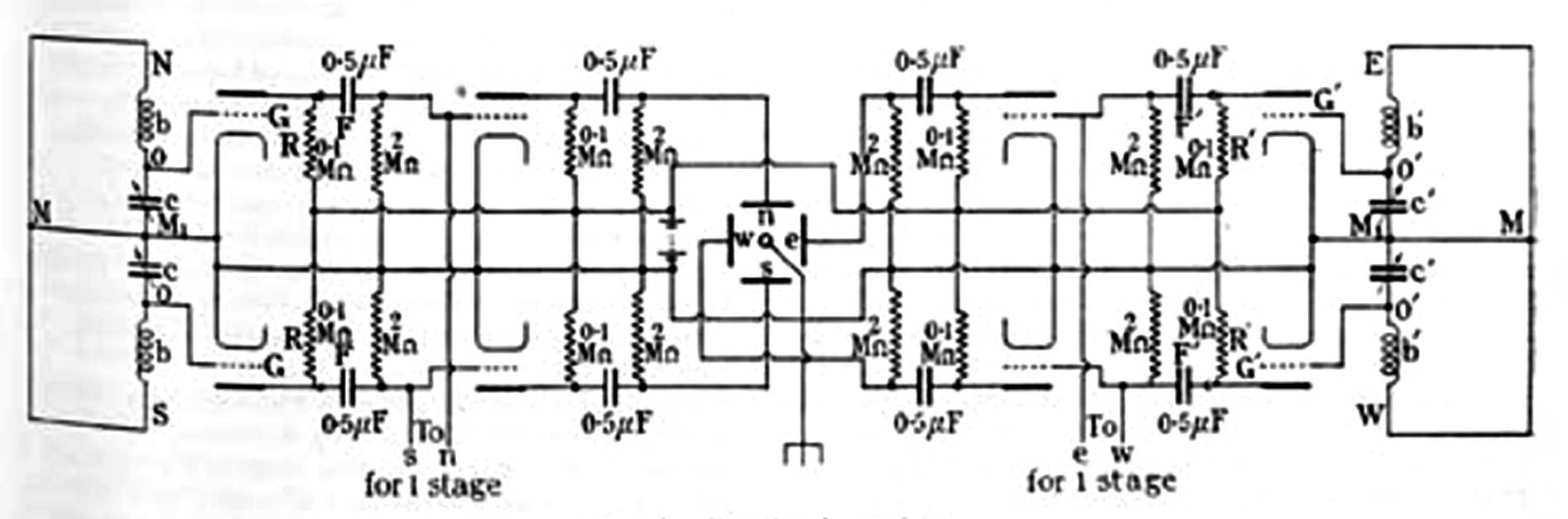
GB252263 - 252,263. Watt, R. A. W. Dec. 3, 1924 - One loop (North-South) connected directly to the vertical deflection plates of a CRT and another (East-West) loop connected to the horizontal deflection plates of a CRT.
1632080 Electric
                discharge device, Johnson John Bertrand (Wiki), Western
                Electric Co, App: 1921-12-27, - Braun Tube (Wiki: CRT)
1632080 Electric discharge device, Johnson John Bertrand (Wiki), Western Electric Co, App: 1921-12-27, - Braun Tube (Wiki: CRT)

Hot cathode version of the Braun Tube.
The Inventors: Karl Ferdinand Braun -
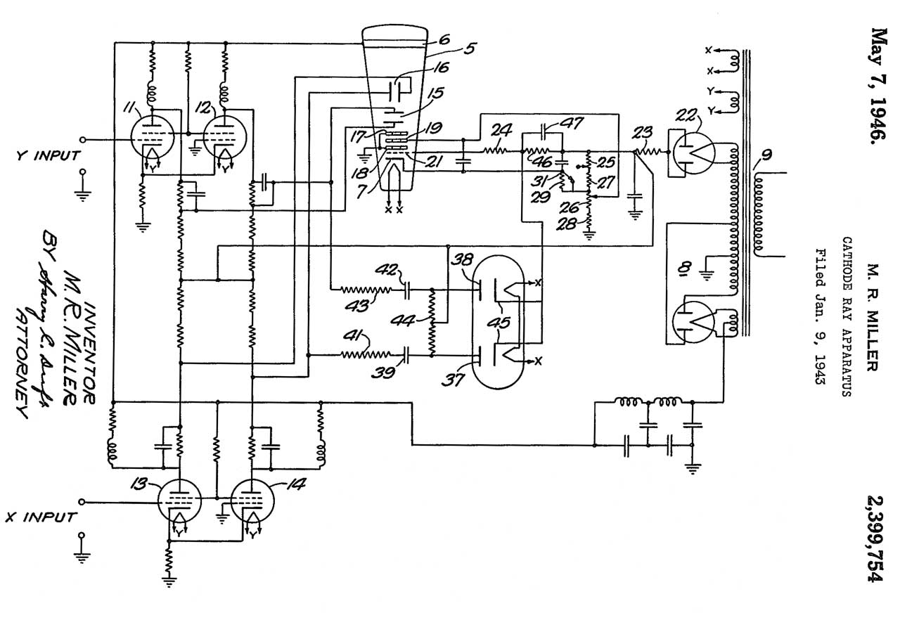
2399754 Cathode-ray
                apparatus, Merton R Miller, Western Electric Co, App:
                1943-01-09
2399754 Cathode-ray apparatus, Merton R Miller, Western Electric Co, App: 1943-01-09, -

The X and Y inputs are AC coupled in this patent and sort of balanced (note how the positive input goes to the gird of a tube and the screen grids of the complementary tubes are connected while the grid of the negative input tube is grounded.  This allows the use of a single polarity HV power supply.  But better balance might be achieved if a symmetrical HV supply was used, like what would be required for Fig 3 above.

In Fig 3 above the deflection amplifiers are balanced and AC coupled.

Related Web Pages

IMDB: Castles in the Sky, 2014, "It is the mid-1930s and the storm clouds of WWII are forming in Germany. This film charts the work of Robert Watson Watt, a pioneer of Radar, and his hand-picked team of eccentric yet brilliant meteorologists as they struggle to turn the concept of Radar into a workable reality."
Radio Direction Finding
StormScope - aircraft lightening detector
SkyScan Severe Thunderstorm Detector -
Weather -

References

Ref 1. Tesla Death Ray Power Secret, 14:24 - Some misconceptions about Tesla Coils.

Links

PRC68, Alphanumeric Index of Web pages, Contact, Products for Sale
This web page created 2020 July 9