Audio Adapter Assembly
The Audio Adapter Box has three BNC(f) connectors labeled Receive
Output, Transmit Input, and Transmit Meter. A standard U-229
(5 pin) connector on a cable connects to the PRC-68 AUDIO
connector. There is a "Push to Transmit" button on the lid.
AUDIO pin A connects to the box ground
AUDIO pin B connects to the Rx Output center contact and there
is a 62 Ohm resistor to ground (mutes internal speaker)
AUDIO pin C connects directly to Tx Meter center contact and
then goes through a PI attenuator to the Tx Input
connector. The attenuator is about -46 dB. This
allows connecting an audio generator directly to the Tx Input
connector and ending up with a mike level drive to the
radio. The actual drive signal can be measured at the Tx
Meter jack.
For receive testing the Rx Output is designed to feed the
TS-723 Spectrum Analyzer. For transmit testing AF
generator URM-127 feeds the Tx input and an audio voltmeter
monitors Tx meter.
There is no DC blocking in this box. I need DC blocking
to eliminate the + 5 to +6 Volts on the B pin prior to feeding
my 4395A spectrum analyzer.
The box itself is a cast metal Pomona model 2901.
It's like the 2428
but with mounting flanges
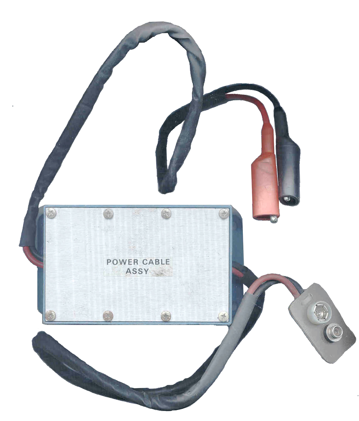
Power cable Assembly
I think when this unit was designed digital metered power supplies
were expensive. Its purpose is to take in DC from 20 to 30
Volts (which includes a military vehicle battery) and output 15.0
Volts. Maybe the "bench" could be located in a com van?
Inside there is an LM7815 in a TO-3 package. The positive
lead has a 0.5 Amp fast acting 1/4 x 1 1/4" fuse and there is a
spare fuse. The output goes to a Squad
Radio Battery Snap for connection to the battery terminals
of the radio (no provision for powering through the AUDIO
connector).
It is housed in the same Pomona Electronics
model 2901
box as is used for the Audio Adapter Assembly.
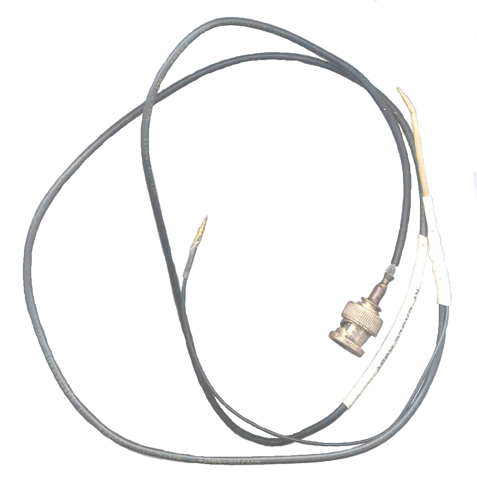
RF cable assembly
This RF cable is made from a 3 foot length of RG-174 coax with a
BNC(m) connector on one and and two pins on the other end.
Both pins have a o.040" diameter point to fit into the PRC-68
printed board test points. The ground lead is about 7" long.
RF attenuator assembly
This assembly takes in the RF from the radio by means of the
antenna adapter and feeds it through a 0.01 uF cap directly to the
Wattmeter output. The Wattmeter center then goes through a
2.6 k Ohm series resistor to the Test Output connector which has a
62 Ohm resistor from its center pin to ground. The two
resistors form an attenuation network.
Power Jumpers
 These are
plastic blocks with a metal strap on the bottom and a couple of
0.040" diameter pins to plug into the fixed printed circuit board.
These are
plastic blocks with a metal strap on the bottom and a couple of
0.040" diameter pins to plug into the fixed printed circuit board.
The one for the transmitter module has the pins 0.472"
C-C. The PCB has a dashed line between TP18 and TP19 in
the area where the Transmitter Module 1A4 fits and this is where
the jumper needs to be inserted when the Tx module is removed so
that some of the other circuits will receive DC Power.
The one for the IF/AF module has the pins 0.895" C-C. The
jumper is connected between E7 and E14.
150 Hz Filter
This is made up of 3 resistors and 3 capacitors in a twin-T
arrangement. From the left connector there are a couple of
22 k Ohm resistors in series going to the right connector.
At the center there is a 0.2 uF cap to ground. From the left
connector there are a couple of 0.2 uF caps in series going to the
right connector. At the center there is a 10 k Ohm resistor
to gorund.
The box is a Pomona
model 3230
that comes with two BNC(f) connector installed.
Antenna adapter
This is the first Magnavox Antenna adapter I have seen that works
properly. As you screw it down you can feel the spring
fingers contacting the hot antenna terminal and it screws down
until the housing bottoms. I have seen about a dozen of
these (including some after market units) and the spring fingers
all hard bottom before the housing bottoms. You can see that
it probably was reflow soldered rather than using an iron because
there is not a pile of solder around the center pin. This is
the standard Magnavox design with no DC return.
See my Antenna Adapter that has a
built in DC return.
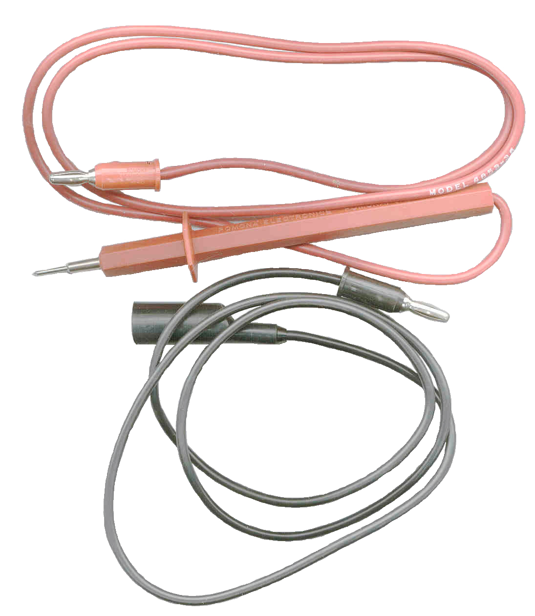
Test lead assembly
This appears to be made up of stock Pomona leads. The Black
lead is a model 1959-36 male banana plug to aligator clip.
The red lead is a model 4853-36 male banana plug to 0.080"
diameter probe. Maybe they no longer make test leads with
the exposed banana plugs or offer individual test leads?
Back to Brooke's page created 20 April 2002.


