
|
|
|
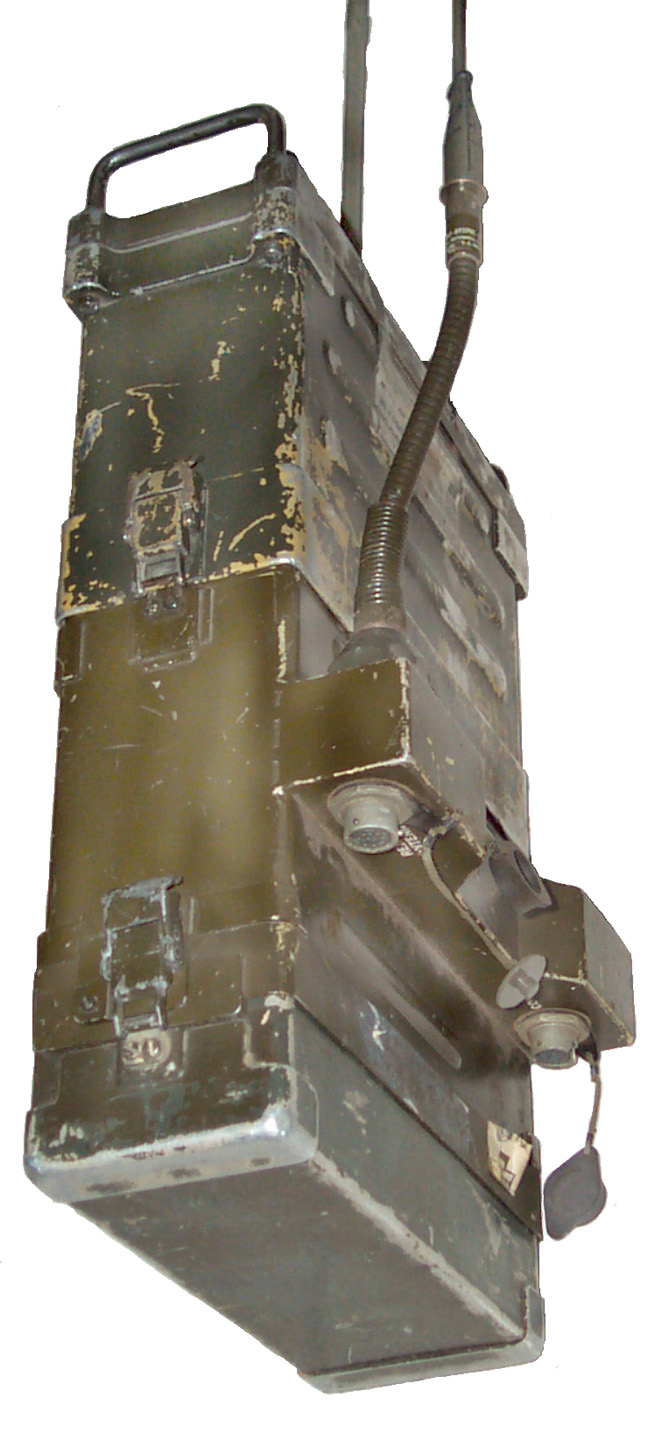
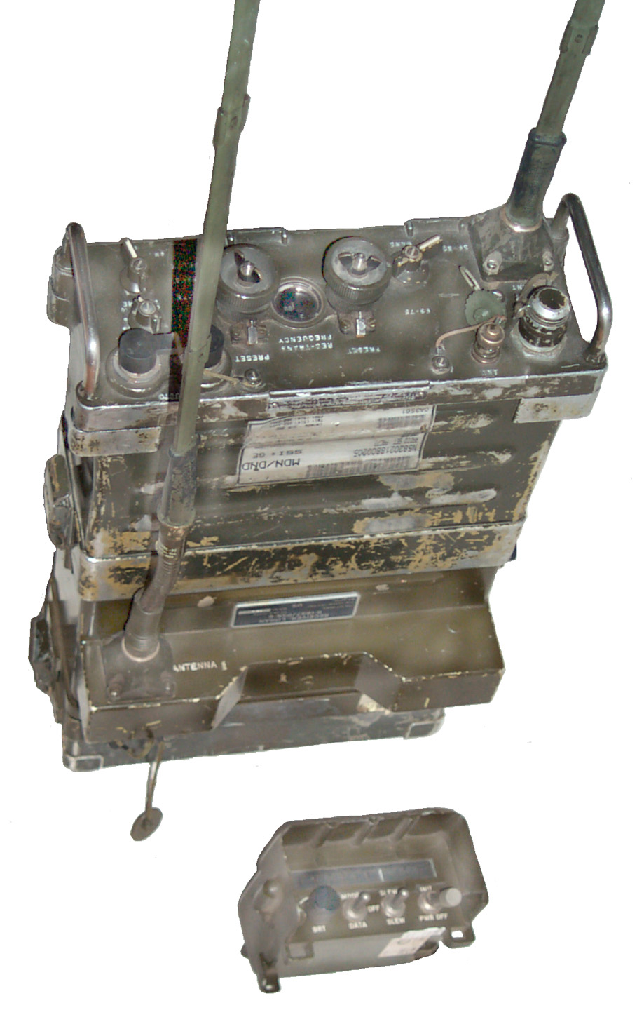
| PSN-6 shown on PRC-25 w/Control Box |
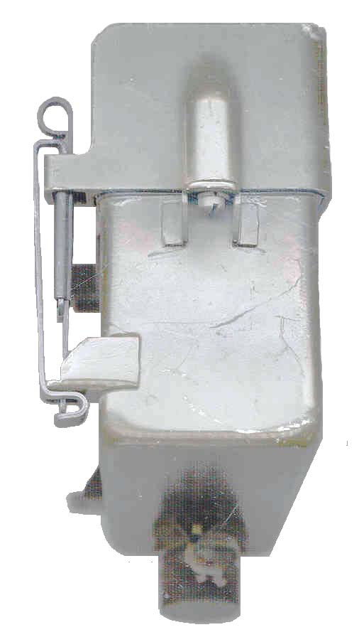
Connectors under PSN-6 |
This is a Vietnam era land navigation receiver and is large when compared to the Desert Shield/Storm hand held SportNav LORAN-C receiver with MGRS.
NSN 5825-01-072-7989 is the 100 kHz LORAN-C or LORAN-D receiver and NSN 5825-01-069-6872 is the Vehicle Mount Adapter that works in conjunction with the AM-2060 and MT-1029 and either a PRC-25 or PRC-77.In a man pack configuration the PSN-6 attaches to the bottom of the PRC-25 or PRC-77. The top of the PSN-6 has a space that acts as the battery box for the radio. A second battery is attached to the bottom of the PSN-6 using the battery box from the radio. On the side of the PSN-6 there is a "shelf". On top of the shelf is the standard PRC-25 antenna block and the AT-892 whip is used for LORAN-C reception. On the bottom of the "shelf" there are two connectors one for the cable that goes to the CX-12984 cable that connects to the C-9547 Control-Indicator. The other is a multi pin connector that connects to the remote antenna when the PSN-6 is used in a vehicle.
When the PSN-6 is used in a vehicle there is a cap that covers the top radio batery box and has a bracket and strap to hold the C-9547.
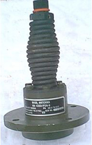
The AM-2060 powers the radio and there would be no room in back for the PSN-6 so it stacks on top of the radio. The Vehicle mount antenna base is the AB-1222/PSN-6 which has a multipin connector on the base.
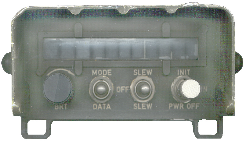
The C-9547 Control-Indicator has an 11 character incandescent display and the following controls:
BRT - brightness of the LED displayOn the back is a Burndy 8 terminal socket 8T07EC12-8 9 this is the same connector used on the radio so the CX-12984 cable has the same connector on each end. The REMOTE ANTENNA connector has the same number of sockets but the orientation is rotated from the CONT IND connector so they can not be cross plugged.
MODE-OFF-DATA - mode control switch
SLEW-OFF-SLEW - slew up or slew down for data entry
INIT-ON-PWR OFF - main power switch and momentary Initialization position. Once in the ON position you can not turn the switch off unless you pull the handle out. This would prevent an accidental shut down that would cause a lengthy signal acquisition process.Note the two square openings shown in the photo of the front of the C-9547 control are designed to accept a pair os standard ALICE clips to allow attaching the control to a pistol belt or other ALICE strap.
Pinlite (now Wamco) 06-30 28564 are the 7 segment digit displays. Pinlite 063 28564 are the 16 segment alphanumeric displays. These Direct View Filament Displays are socketed for easy replacement.
The Burndy/FCI connector was cross referenced by Arrow to an Amphenol part number PT06E-12-8P(SR) that includes the cable clamp. I used some CAT5 LAN cable since I had it. Wired the cable 1:1. The PSN-6 powers up and the display is not LED but rather some type of incandescent display.
The receiver uses the AT-892 1 meter tape antenna and flex base as are used on the PRC-25 and PRC-77. The battery box is the CY-2562/PRC-25 the same as for the PRC-25 or PRC-77 and uses the BA-4386/PRC-25 battery so my 257477BA Battery Adapter should also work.
The receiver provides 10 meters accuracy.
Although the PSN-6 attaches to the PRC-25 or PRC-77 there is no provision to automatically send position over the radio. It's up to the radio operator to send his position using the H-250 handset.
The case for this unit has a cutting torch cut through the Al but the printed circuit cards appear un touched. Either the cards were removed prior to the cutting or someone prior to me has replaced the cards. The receiver is operational.
EPROM
There are EPROMs in the receiver that have been programmed by the MX-9643 programmer, NSN 5825-01-070-3847, with the Loran chain parameters for 16 military UTM grid squares. The Programmer manuals are TM 11-6625-2619-12 and -24P. It includes a UV lamp to erase the EPROM so a new set of MGRS grid squares can be programmed. Note that the EEPROM holds 16 squares in a 4 by 4 pattern, but not necessarily on a zone boundary. Each square is 100 km (62.5 miles) on a side. So the coverage area is a square about 250 miles on a side. By doing this there is no need to tell the receiver an approximate position like is done for the SportNav. This makes the PRSN-6 more robust, but at a large expense and complication in customizing the EEPROMS. Maybe at the time the PSN-6 was designed they did not have large enough ROMs to hold all the Loran-C chains or maybe the customization is to allow for a Loran-C or -D chain setup by the military for use in some part of the world where they are operating.There are two EPROMs. Each is marked MC1702A/B, 7642, 370A7, SMA 762537 001. They both have 24 pins with the two rows 0.6" apart and have been soldered to a ceramic carrier that in turn has machined pins that fit into a socket. I think the idea of this is so the the chips can be removed and replaced without breaking the normally fragile DIP leads. Note these are 1970 - 1980 vintage EPROMs and are the UV erase type, not EEPROM.
My 257477BA Battery Adapter works fine with the PSN-6.
Following the manual instructions for the EPROM ID results in:
SCH = Searching for stations about 5 to 10 seconds
STL = Settling down for a searching (up to 12 minutes, or in my case never becasue I'm not in NC)
Using DATA mode and SLEWING to the ID field gives:
USA19 = This is the EPROM mentioned in the manual, USA22 is for Key West, FL
Feb 12 98 = The date in the manual is 27 APR 77, so this is newer
NM, PM, QM, TS, NL, PL, QL, TR, NK, PK, QK, TQ, NI, PI, QI, TP = 16 grid squares in the Fort Bragg area of NC.
84Wx40N
78Wx40N
NM PM QM TS
NL PL QL TR
NK PK QK TQ
NI PI QI TP
84Wx32N
78Wx32N Ft. Bragg is in North Carolina at about 79W x 35N.
There are 3 Loran-C chains that might be utalized: Great Lakes 8970, S. E. U. S. 7980, and N.E. U.S. 9960.
The EPROM should have one or more of these in it. This might be a way of reverse engineering the EPROM, i.e. looking for the data from these chains (see my Table of U.S. Loran-C stations).The Display Test lights all segments on the display.
AAANNNNNNN
The left 3 characters are alphanumeric (i.e. can be either a letter or number) the right 6 characters are only numeric.The Delta Time A and B functions are reporting numbers like A = 419 96 and B = 568 61, but they move up and down.
The Micrologic SportNav Loran-C receiver would not sync inside so I'll take the PSN-6 outside and let it try and sync.
Even with the incandescent display characters it's very difficult to read the display in broad daylight, even in the shadow of your body.No luck. I think that the PSN-6 must be in the USA-19 grid square shown above in order for the receiver to sync.
If you leave the display showing "USA19" after 30 seconds it will switch to the test pattern (all segments on) and then go to a way point display (a digit between 0 theorugh 4 on the left and 7 digits on the right.
TM 11-5826-251-12, Change 1, June 1979
TM 11-5826-251-12-HR
TM 11-5826-251-24P
TM 11-5826-251-34 (restricted)
TS-3506/PSN-6 is a LORAN-C test signal generator for use in field testing the PSN-6. It's manual is TM 11-6625-2707-12 and the NSN is 5825-01-076-1777.SM-708 is a LORAN-C signal simulator for bench testing.
It may be that by using the Austron A2042 Loran-C Simulator programmed to be one of the chains near North Carolina, it would work?
Table of U.S. LORAN-C Stations -
USCG - Loran-C Users Hdbk - Apendix B.pdf - has more chains and coverage diagrams
PSN-9 (sic should be called a PSN-8) is a GPS version but only 18 meter accuracy (maybe that is an out of date number?) 1987 BA-6598/U 9.8 WattsBack to Brooke's Products for Sale, Naviagtion, PRC-25, Military Information, Home page
[an error occurred while processing this directive] page created 16 June 2002.