Austron 2042 LORAN-C Simulator
© Brooke Clarke 2005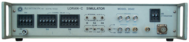 |
 |
 |
 |
Background
So far I've not found any documentation
on this unit of any kind, if you have any please let
me
know.
Until the advent of an operational GPS system LORAN-C was the most accurate radio navigation system available, but since it was designed for coastal waters there were many places in the World without any LORAN-C signal. Because of it's growth LORAN-C chains were put into place in areas far from coastal waters so that aircraft could use LORAN-C for navigation.
LORAN-C using a pulse transmission at 100 kHz also replaced the WWVB amplitude modulated signal at 60 kHz as a very stable time transfer method.
A LORAN-C station has antenna towers that are maybe hundreds of feet high and runs a huge amount of power. Note that a 1/4 wave antenna for a frequency of 100 kHz needs to be about 750 meters or 2,460 feet high, way higher than any antenna tower. So a number of towers are used with top loading horizontal wires. When a whip that's 3 feet long ((like the 2042 built-in whip) the antenna is only 0.0003 wavelengths long and so is extremely inefficient. What this paragraph is saying is the the range of this simulator is probably measured in feet or inches.
Email from Ken:
My brain is a bit foggy on the 2042.  I worked with these a long time ago.  But they were intended to either radiate through the attached antenna or inject a signal directly through a twinax connection as I recall.  Their range of radiated operation depends on the receiver but certainly no more than a few feet.  Frequently you will have substantial in band interference when trying to use the radiated output indoors from anything that radiates in the 90-110KHZ range that will block the receiver.  Also if you have a very sophisticated loran c receiver they are hard to use due to the signal amplitude being constant on all "stations".  These were manufactured somewhere between 1982-88 I think.

Ken
Description
Sep. 25 1979 date stamps appear on the
PCBs and the OCXO label has 9/79 as Date Mfg.
The front panel controls are left to
right:
- On-Off switch in a cylinder to prevent accidential actuation.
- 4 Digit thumb wheel switch to set GRI (my local chain is 9940, but for testing some other GRI would be needed)
- 5 Digit thumb wheel switch to set Slave A coding delay
- 5 Digit thumb wheel switch to set Slave B coding delay
- 3 toggle switches to set the interval sequence (A-B-A or B-A-B) for the Master, Slave A and Slave B
- 3 toggle switches to set the Master, Slave A and Slave B to either OFF, ON or Blink
- 3 BNC jacks with Decode outputs for Master, Slave A and Slave B
- a 3 position toggle switch associated with 3 BNC jacks, where the
switch positions are Master, Slave A or Slave B
and the 3 Jacks are labeled Trigger above the first 2 and Sync above the third,
and Stop, Start and Input under them. - 2 Digit thumb wheel switch for dB of Attenuation 00 to 59 dB range with lines indicating that it feeds two connectors
- A BNC jack and a Twinax connector (two center pins and a ground shield.
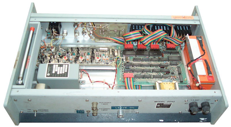
- toggle switch "Antenna Control On - Off
- toggle switch Internal or External standard
- BNC jack for Buffered 1 MHz out
- BNC jack for External 1 MHz input
- toggle switch in cylindrical sleeve to prevent accidential operation for Oscillator On or Off
- 1/4 Amp AC fuse
- 1 Amp DC fuse
- IEC line powercord socket
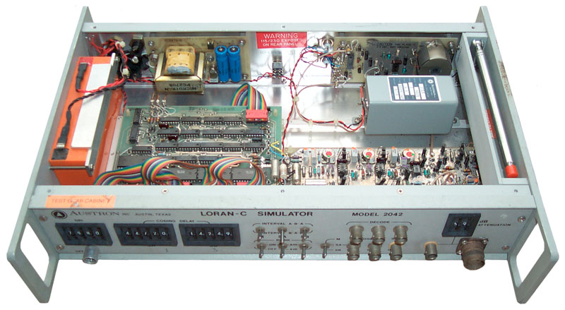
Major components
On the rear panel there is a power supply PCB and another PCB that drives the 3 foot whip. The whip storage cavity has a warning sticker "Do Not Short Antenna to Chassis" and the whip driver PCB has marking CAUTION Foil Plane is + 3 VDC, NOT Ground. The same caution is on the RF generation PCB. The large PCB ( 5 x 6 inches) has a lot of CMOS logic. The adjacent PCB (2 x 8 inches) may be an RF board.There's an OCXO with a Tune screwdriver adjust and no EFC, just DC power in and RF out. It's output goes to the rear panel whip PCB.
A Gelcell battery, maybe 7 AH long dead.
A small PCB on the front panel behind the 6 central toggle switches is just a wiring saver, no ICs, labeled "Function Switches Interface Card".