
 |
 |
I personally don't like the idea because then sundials would not
tell the correct time. A well made sundial today can be
accurate to a few seconds since UTC is kept within a fraction of a
second of Solar time (i.e. the Earth's rotation). If we
allowed the difference to get as big as 10 seconds, then sundials
would have this amount of difference to common time.
Another larger problem is that if making the correction is put
off then when it needs to be made there will be many more
problems. This is what happened with the Y2K problem.
There was a lot of scurrying for a few years prior to Y2K to fix
the problems and a number of items have since been scrapped
because they were not compliant. If the leap seconds are
left as they are then equipment designers will allow for their
insertion and most designers will see a number of leap seconds
during their carrier. But if the correction is put off for
much more than 20 years, then it will be a case of "I don't need
to worry during my career so let's leave it to the next guy".
| GPS
carrier phase time transfer |
e-11 |
| GPS 1 PPS | e-8 |
| Loran-C
1 |
e-7 |
| WWWB WVBH LF time stations 1 | e-7 |
| VLF radio carriers (military RTTY stations) 1 | e-6 |
| carrier of local AM or FM station 1 | e-6 |
| Chirp Receiver from GPS controlled Tx 1 | e-6 |
| WWV WWVH HF time stations 1 | e-5 |
| NTP | e-5 |
| CDMA | e-5 |
| Photographic
Zenith
Tube 2 |
e-3 |
| Sun Meridian crossing w/current ephemeris 2 | e-2 |
| Telephone audio time recording | e-1 |
| TV color burst | e-0 |
| Internet web page clocks | e+1 |
| Sundial w/ EOT correction 2 | e+2 |
| Sundial w/o EOT correction 2 | e+3 |
| Astrolabe 2 | e+3 |
From the Electric
Clock ioGroup Mon 17 Jun 2024 in email from klopschip.
The following link has an excellent history of radio time
transfer.
1922 Brillie
1929 ATO (ATO Electric Clock) - Radiola-ATO - "The signals provided by Radio-Paris, were broadcast as a sequence of six 'rhythmic' dots ending on the exact time, similar to the six pips provided by the BBC. The amplified and rectified pips of the signal were passed to the coil of a 1/4 second electromagnetic pendulum that immediately started to swing in sympathetic motion and in so doing closed a switch thus acting as a relay."
Note this is item 42 in Fig 3 of patent FR35652 and is has a 1/4 second movement, i.e. it is not a time keeper, but rather the relay that controls the clock.
Photo from the Electric Clock ioGroup Mon 17 Jun 2024 in email from klopschip
FR643873A (EN.pdf) Remote control method and devices applicable in particular to automatic time reset of clocks, Leon Hatot SA France, 1928-09-25, -
French Patent FR35652 Remote control methods and devices applicable in particular to the automatic time setting of clocks, Leon Hatot SA France, 1930-03-27
Time Broadcast Stations
The stations purpose is to disseminate time. These time broadcasts occur in different frequency bands. The most common are in the Low Frequency (around 40 to 80 kHz) and High Frequency bands (around 2.5 to 20 MHz).
Navigation Stations for Time
Some types of navigation radio stations have very precise frequency and or timing characteristics that can be used for time transfer. LORAN-C and GPS both are extreamly good at time transfer. GPS being the best method for most applications.
Stations for Frequency
There are (were ?) special built receivers to Phase Track the military VLF radio teletype stations thus prividing a stable output frequency.
The television color burst signal used to be live from the network studio and could be used as a standard, but with the advent of digital time base correctors is no longer suitable.
L.F. Time Stations
China - BPC 68.5 kHz proprietary protocol
France -TDF - 162 kHz -
Germany - PTB - DCF77 - DCF77 Receiver resources page (phase modulation similar to the new WWVB scheme)
Japan - JJY - 40 kHz
Switzerland - HBG - 77 kHz - Clock makers -
UK - NPL - MSF -60 kHz - BBC4 - 198 kHz -
US - WWVB - 60 kHz - manufacturers of time and frequency receivers .Information
Brooke's Frequency Assignment Table
Gude analog & Digital - Time receivers for: DCF, HBG, MFS & GPS (no WWVB)
HKW-Electronics - UE6010/11/15/20 LF time receiver ICs, antennas, modules, etc.
Radio Österreich International - list of time stations -
Standard Frequency and Time Signal Stations On Longwave and Shortwave
Time Stations by AC6V
WWVB - 60 kHz
WWVB can be used for two different purposes:
(1) as a phase reference to determine the frequency stability of an oscillator
(2) as a source of amplitude modulated digital time code data to set a clock that includes leap years and leap second data.
The leap second data is done with 2 bits in such a way that the clock can make the jump at the proper time.
Starting in the 1990s there are a number of low cost clocks and watches that set themselves called "atomic clocks" based on this service.
Note that GPS is a world wide system that does NOT have any leap year or second data. It does have a UTC to GPS time differential that will allow a clock to display the correct UTC time to within a second after about 12.5 minutes of the correct time to make the jump. GPS does not have any bits for DST.
3032650 Frequency standard receiver, Richard P Mathison, Lloyd J Derr, California Institute Research Foundation (Cal Tech), 1962-05-01, -
HP 117A WWVB Receiver & Phase Comparator
I bought the HP 117A VLF Comparator from EIP Microwave since they had replaced it with a Loran-C based system. It uses Nuvistors in the loop antenna and the 60 kHz amplifier block that are hard to find. I have replaced them and now it works well. I would like to use a PIC microcontroller to decode the time signal. The stock unit only looks at the phase difference between the external signal and the phase of WWVB. You can see the hourly 45 degree phase shifts on the WWVB carrier as well as the diurnal variation in phase of the signal from WWVB.
Found a source of contact type strip chart paper (see Amprobe below) : width = 2 1/2", plot width = 1 15/16", sprocket holes on both sides of paper = 0.1 ID on one side and slots 0.1 x 0.15" with a 1/4" c-c pitch. along the edge is says: HEWLETT-PACKARD RECORDING CHART NO. 9281-0081
Example plot showing adjustments being made to an HP 107 oscillator. You can see the hourly phase shifts on the WWVB carrier.
The strip chart drive in the 117 may be the same as an Amprobe model DB81 that uses Amprobe model 850D chart paper.
10509A antenna for the HP 117A
WWVB Time Receivers
NIST has increased the power of their time station WWVB on 60 kHz so that the East coast of the U.S. will have a stronger signal all year.
For the month of March 2005 - NIST does experiment by using a 20 dB modulation depth instead of the standard 10 dB modulation depth on WWVB & WWVBH to help time code type clocks. But this may cause phase lock type receivers, like the HP 117, to have trouble maintaining lock.
Temic (2007 now C-Max) has a series of Time Code Receivers that have selectable 40, 60 or 77.5 kHz input frequency and built in knowledge of the time codes used in diffeent countries. C-Max is in Germany, where Temic was and there is some continuity. Also make time transmitter simulators to test LF time receivers (needed since the LF signal strength to the receivers has a very wide range.
Historical Info on Temic
They have changed their web page and I can no longer find information on the U 4223 B-CFS. It is packaged in an SSO20 surface mount package, the only other version is a raw chip. The SSO20 package has 0.025" pitch connections which is 4 times closer than a DIP with 0.1" pitch. So far this has been a problem in building a prototype. A loop that should work with C-Max IC.
PSN network note about Temic receivers.
Searching the Temic-semi web site for WWVB returns 5 documents:Agilent 4395A - If an active external antenna like the Dymec DA-100, that can pick up the 60 kHz signal from WWVB is connected and the center frequency is set to 60 kHz, span to 100 Hz, RBW to 100 Hz, then the sweep time is 45.71 ms. The display jumps up and down 10 dB in step with the time code modulation on WWVB. The number of points is set automatically to 5. 4395A Spectrum Plot 50 to 150 kHz. The triangular peak centered on 100 kHz is LORAN-C.Time-Code Receiver with TC Output - U4226B Time-Code Receiver with Digitized Serial Output - U4224B Low-Cost Time-Code Receiver - T4225B Time-Code Receiver with A/D Converter - U4223B Time-Code Reception -
Arctime - sells a number of Ziet clocks that work by receiving LF time signals
A Radio-controlled Digital Clock - PIC based with LCD display
B Roehrig, "Most Accurate Frequency Standard, Parts 1,2,3", 73 magazine, Jan/Feb/Mar 1994.
Circuit boards available from FAR Circuits This is a WWVB frequency standard and needs additional circuitry to demodulate and decode the time signals.Elmer's Guide to Atomic Clocks for the Home and Office -
Gunter - AK2124 SOP 24IC - AK2125 SOP 14 IC - AK2127 raw chip or SOP 16 IC -
Klockit - sells a movement to drive conventional hands.
This ships with a pin to lock the hands than must not be removed until it is installed and the hands attached. I used one to convert a Wal-Mart clock to WWVB controlled. (You might look for an ALL plastic clock for better reception.) Klockit now has a complete kit in addition to the movement. When I built mine I needed to order the second hand separately, be sure to get all three hands with the raw movement.Precitel Co. - Time Products for VLF and GPS including public clock movements
Quartzlock Instruments - WWVB receiver and precision time standards
Radio Clock - a PC sound card based software package that decodes the audio WWVB signal from your receiver and sets the PC clock. Made to support BeaconSee for ham radio propagation monitoring. They also have a free applet for GPS PC clock synch.
Radio Clock Control, the Netherlands - offers slave clock pulsers that are mains or LF time signal driven.
Radio Shack's Radio Controlled Clock to SDR Interface - info on Blob cable
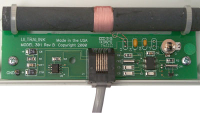
Ultralink, Inc - OEM TTL version, RS-232 and one with analog signal strength meter
Ultralink 333A WWVB receiver with special firmware
Ultralink WWVB antenna (marked 301)
U1 (on right) is a U4226B Temic WWVB receiver and U2 (at the left) is a TI 2771C Op Amp
The RJ-11 Pins are: 1 = nc, 2=Vcc (2 V), 3=TimeCodeOut, 4=AGC (Signal Strength), 5=Gnd, 6=nc
UL333 Antenna & RF decoder , Data Decoder & Display it's now a UTC only time display, but might have be upgradable to local timeUniversal Time Company - custom clocks as art
The US Time zones are selectable as well as UTC. With UTC there is also an option for continious RS-232 output (9600-8N1).
WWVB Receiving Antenna (bike wheel & soup can) - WWVB signal processor-
HF Time Stations WWV - WWVH - WWVS
The WWV (Colorado) and WWVH (Hawaii) stations can be used in a number of ways:
(1) audible voice announcement of the time every minute with audible second ticks
(2) audible voice announcements about a number of topics at specified minutes past the hour
(3) AM modulated digital data on a 100 Hz subcarrier with time code data similar to WWVB. The Heathkit GC-1000 used this signal.
It had a bug in that the switch to/from standard time/DST happened when Colorado changed, not in your time zone although there were DIP switches for time zone as well as propagation delay in ms. In California it was wrong by an hour or two twice a year if set to display local time. There may be a modern CPU chip replacement for the GC-1000.
Power supply reliability upgrade information by Jeff Thomas - replaces the linear 5 volt regulator with a PT5101A-ND switching mode power supply on a daughter board.
More Accurate Time from the Heathkit Most Accurate Clock by USAF Academy - from +/- 29 ms to +/- 3 ms by adding a 1 PPS output on the DB-25 pin 7.
Another problem was that when the power failed the GC-1000 used the backup battery to keep the LED display on thus quickley draining a small battery. It would have been better to shut down the LEDs when the AC line failed and keep the oscillator going. Heath April 15, 1986 patent on the GC-1000 is 4582434.
An improved WWV-WWVH receiver is the Precision Standard Time Model 1020, it locks quicker and has less problem with false locks.
In my T&F rack there is an HP 1148BR Time Comparator and HP 120 oscilloscope and an HP 113AR Frequency Divider and Clock.
The 114 takes in the audio from a HF receiver tuned to one of the WWV stations. It feeds that audio to the 120 scope Vert. and a 1 PPS to the Hor.
The 1 pps can be moved in 1 ms steps using the 3 thumb wheel switches on the 114.ESE - ES-180A WWV master clock -
Austrailian Standards Leaflets - Radio VNG 2.5, 5.0, 8.638, 12.984 and 16.0 MHz.LORAN-C
The LOng RAnge Navigation system version "C" was a follow on to the A version that worked around 1.9 MHz which is near the peak absorption frequency (1.6 MHz) of the ionosphere's "D" layer. It has maximum density when the Sun is at local noon and goes away at night. This has a strong effect on AM broadcast stations and I'm sure on the old LORAN system. LORAN-C operates at 100 kHz where the ground wave is very stable. Since it's a pulsed system a receiver can seperate ground wave from sky wave unlike WWVB where they get mixed up. This makes LORAN-C able to transfer time more accurately than WWVB at 60 kHz.
Data Channel
The current LORAN-C system does not now broadcast data packets. A part of the eLORAN modernization program may be to add a Data Channel. This would be similar to what's now done as part of GPS and would include the time and date, station ID and location, etc. Like the GPS system the LORAN system will not have leap seconds, but will have a couple of bits to allow determining exactly when a new leap second will happen as well as the current offset between LORAN and UTC so that UTC can be accurately determined. What's missing is domestic Daylight Savings (Summer) time bits, like are on WWV and WWVB.
Why the LORAN-C Data Channel should include Daylight Savings Bits
It would enable precision clocks that keep local time.
Currently it's straight forward to make a clock that tells UTC and these are used for scientific purposes throughout the world. But it's very difficult to make an equally accurate clock that tells the local time. For example Heathkit used to offer the GC-1000 digital clock that was synchronized by the WWV and/or WWVH radio stations but it has a couple of problems, 1) the switch to/from DST happened when the WWV(H) transmitter switched, not at the proper local time and 2) H.F. radio is about the poorest quality time synchronization method available today, many orders of magnitude from GPS or LORAN-C.
WWVB is much better and is now used to synchronize "atomic" clocks. It too has a few problems: 1) there's a diurnal variation caused by the interaction of the ground wave and the sky wave, and 2) the signal is very weak in many U.S. locations so that most clocks can only get a strong enough signal around local midnight, and 3) even when it's working the precision is far from GPS or LORAN-C.
Note that the GPS signal is very weak and does not penetrate into buildings and so can not be used for economical local clock control. Even if an outside antenna is used GPS can not be used because it's not practical to have a couple of DST bits on GPS where each country in the world would have their own, i.e. it would take hundreds of bits. No DST bits = no local time.
That's not a problem with LORAN-C since the signal only carries for some hundreds of km. If DST bits were in the LORAN-C Data Channel specification as a local option then each country could choose to use them for their local time or not and it would not burden the system or neighboring countries.
LORAN-C stations are not only very powerful but are spread all over the world. The LORAN-C signal is very strong when compared to a LF time signal and so could be used to synchronize local clocks. LORAN-C blankets the entire US with a signal stronger than WWVB (1800 UTC part of east coast is off coverage map).
Currently each country has it's own LF time system for local clocks. There is no world wide standard so there's a bunch of independent companies working on a clock for just their country. Since they are on different frequencies and use different protocols this work can not be shared. By standardizing local time broadcasts everyone would be using the same clock leading to a greater range of products from lab quality instruments to dime store clocks more accurate then the existing WWVB clocks.
Timing of Transmitted Pulses
In a hyperbolic navigation system the thing a receiver measures is the time interval between the pulses from each station. The original LORAN systems were thought of as a group of 3 to 5 stations acting alone (not relating to any other chains). The master station of each chain waits for a time that's called the Group Repetition Interval (GRI) between sending it's pulses. The slave stations each wait for their own unique amount of time after the master station then transmit. All the stations in a chain have the GRI between their transmissions. So if you trigger a scope at one of the published GRIs from a stable time base and feed the scope input from an antenna you will see some pulses at fixed time delays from the members of that chain. Also visable will be unsynchronized pulses from other chains. When one of the unsynchronized pulses lands on top of one of the stable pulses it's called cross chain interference.
Another aspect of the modernization is controlling all the LORAN stations time of transmission based on UTC instead of the master then slave method now used. When all the LORAN stations have their transmission times controled by UTC then instead of thinking of each chain seperatly the whole system can be thought of a one big chain. Since each classical chain is transmitting using it's unique GRI the existing LORAN receivers will not see any difference. But then it would be possible to build a LORAN-C receiver that's "All in View" instead of chain specific like is now done.
Table of Loran-C Chain Stations -
International Loran Association - Prior to GPS Loran-C was the best available broadcast time signal (except for an expensive satellite system)
The U.S. Coast Guard controls LORAN since it's primarly a coastal navigation system. So this is where you find the specs, status, etc.
Chirp Sounders
There are many H.F. radio transmitters that sweep from 2 to 30 MHz for the purpose of studying the ionosphere. Many of them now use GPS to keep their start times very accurate and could be used as time transfer transmitters. RCS-5 based and DSP based receivers.GPS
WWVS (WWV Satellite) is a time system that is was replaced by GPS) on two GEOS sats, one one the East coast and one on the West coast. The sat was nominally geosnychronous, but there were variations in the orbits that showed up as time variations.
See my write up on how Sputnik led to the Transit satellite navigation system that lead to GPS. GPS receivers do not need the precision clock that was required for Transit receivers.
This is done by requiring 4 satellites, 3 for position (X, Y and Z) and a forth to remove the requirement for a precision clock in the receiver. There are no bits in the GPS data for the U.S. DST to/from Standard Time. There is an offset number that describes the number of seconds that GPS time differs from UTC. This is needed because the GPS system does not have any leap seconds and UTC does so you can know UTC by listening to GPS.GPS is now the best time transfer method available for most applications.
GPS All in View
The GPS system is designed so that you can get a fix if 4 satellites are being tracked and early GPS receivers worked with 4 satellites. Later GPS receivers are of the "All in View" type where as many satellites as can be tracked are used in the solution since this reduces the error in final position (or time). To take advantage of "All in View" the total number of satellites that a GPS receiver can track has been raised from 6 or 8 for the early receivers to 12 which is practically the most that could be seen for a nominal constellation of 24 satellites. (But there's more like 30 operational GPS satellites now so the receivers should have 15 or 16 channels.
PIC Microntroller Based Motorola Oncore VP+ Binary Time & Date Display
This is a PIC16F84 based circuit that reads the binary data stream from the VP+ and formats the data into DOW, DOM, Month as a 3 letter name, YYYY, hh:mm:ss and displays the data on any standard 44780 based alphanumeric LCD. Since the display is only reading the data it will automatically show leap seconds. It will show local or UTC time depending on how the VP+ was programmed by an external computer. I plan to add dip switches so that you can select the number of columns and number of rows.
GPS Disciplined Oscillators
These combine the long term stability of GPS with the short term stability of a crystal or Rubidium oscillator to end up with an oscillator that does not to be calibrated every 6 months. For more about this see the Allan section below.
Brooks Shera's GPS-Controlled Frequency Standard
I think this one has the best specs, but it was designed when the Motorola 6 & 8 channel timing receivers were common. Now there are newer 12 channel timing grade GPS receivers that have more like 9 ns jitter instead of the 52 ns of the older receivers. This means a new design is needed to take advantage. There is a PIC microcontroller used to steer an oscillator based on the 1 PPS from a Motorola GPS receiver.
James Miller Simple GPS Stabilised 10 MHz Oscillator
Based on the Rockwell/Conexant/Navman Jupiter GPS engines is that they have a 10 kHz output.
Complete Unit
Do-It-Yourself version
Murray Greenman - The GPS Disciplined GPS Clock
Uses a frequency lock loop to minimize the total cost, but at the expense of some performance.
??? new GPSDO from Australia 2007
Motorola 8 Channel Sawtooth Corrector
I used this combination to try and use the saw tooth correction feature on the 8 channel Motorola VP GPS receiver, but there was a glitch in the Motorola saw tooth. Some times the corrected 1 PPS would be low, but never high. So you were better off averaging the saw tooth than correcting it since the saw tooth error was symmetrical. There's a rumor that HP figured out how to get around the bug based on the timing between the glitches being related to the clock speed of the GPS receiver and how it related to the granularity of the saw tooth.
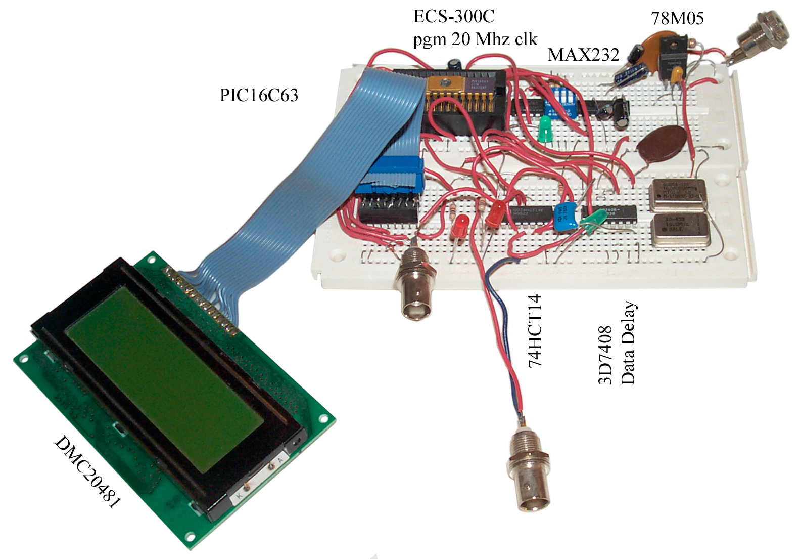
The circuit uses a PIC16C63, ECS-300C programmable clock, 74HCT14, Data Delay Devices - 3D7408 8-bit programmable time delay, Opterex DMC20481 LCD and 78M05.
An adapter was made from 2x7 ribbon cable to 0.3 inch DIP plug so that the LCD could be plugged into the white protoboard. A ZIF socket holds the windowed PIC. RS-232 wiring to the Synergy GPS development black box not shown in photo.
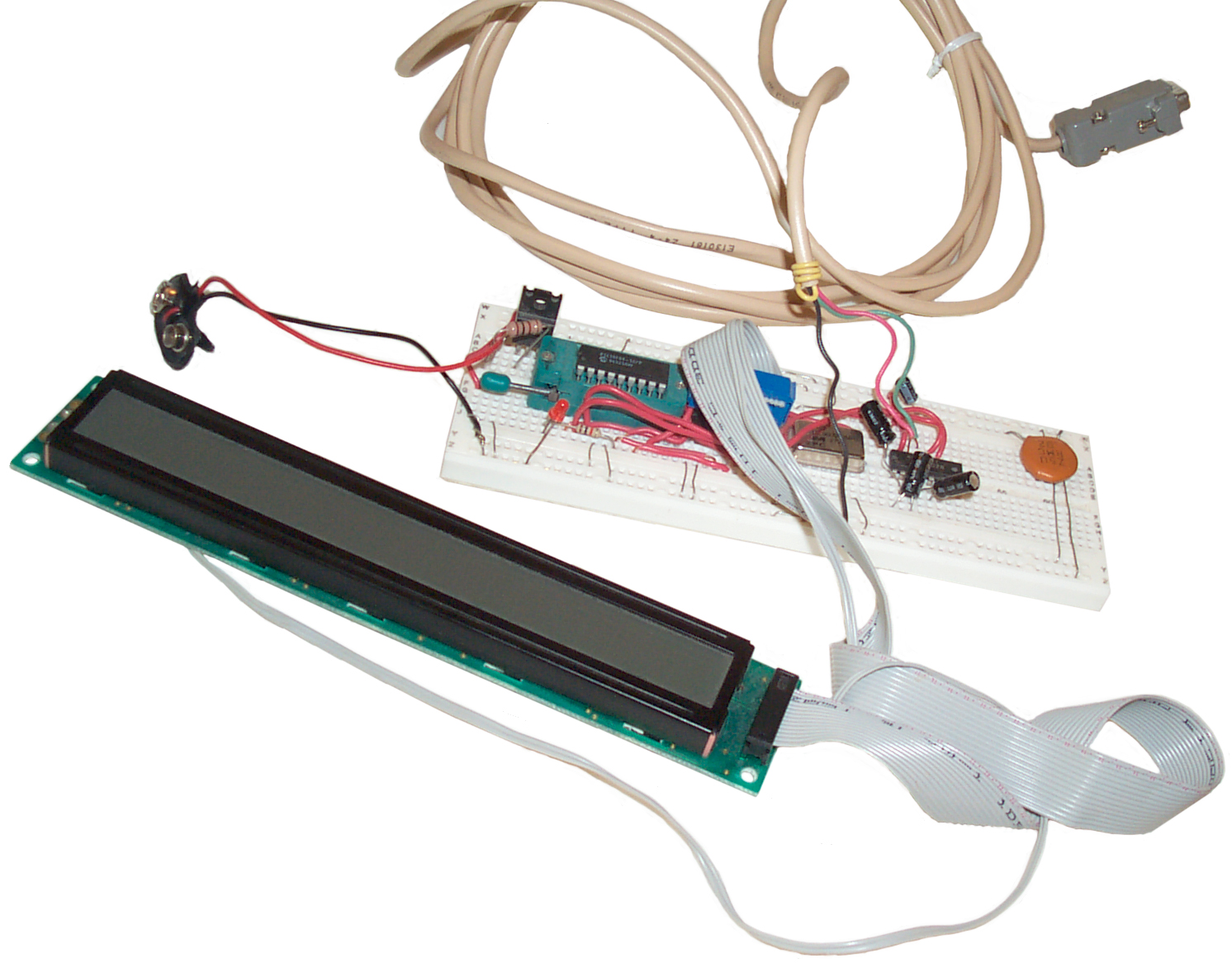
Motorola 8 Channel Binary Packet Reader
This is the PIC circuit that reads Motorola 8-channel binary data an displays some packets in plain text on an LCD. Uses 1 PIC16F84, 10 MHz unit oscillator, MAX232N and 78M05A. It's powered by a 9 volt battery. Also an adapter from 2x7 ribbon cable to 0.3" DIP for the 2x40 LCD that has no markings. I expect that the GPS interface cable shown here was used on the above saw tooth corrector.
The HP-48 calculator has a serial interface and can be programmed to read the packets.
About this time I had written a Lab VIEW program to compare the SC 10 to GPS over a few hours and could fit a parabolic curve to the difference and solve for the aging of the SC 10.
GPS related links
CNS Systems - commercial TAC32 clock - GPS Time - Low Cost High Accuracy GPS Time paper from ION
TAPR - TAC32 - for TAPR members for non-commercial and personal use
Horita - GPS based Video Time Code generators
HP GPS based timing products & app notes
KEK GPS Clock System - TACGPS backup module -
New Zealand and Australia Time Resourses - sub second timing for astronomical use
Symmetricon - is taking over the HP (Agilent) GPS based timing products 58333A, 58540A - I think these used the discontinued Motorola Encore VP series OEM boards.
W7CQ page on the Shera setup with onfo on the HP(Agilent) 10544A
Zyfer - GPS diciplined 1PPS & 10 MHz -
Luis Cupido - Board to phase lock an oscillator to either a 10 MHz input or a 1 PPS input
Rockwell/Conexant/Navman Jupiter GPS engines that has a 10 kHz output
Simple GPS Stabilised10 MHz Oscillator - would be better using the TVB PIC as the divider rather than the 74390 parts.
Probably the Simplest GPS Disciplined Oscillator possible ! - by Andrew Talbot, G4JNT
INITIAL RESULTS OF THE NAVSTAR GPS NTS-2 SATELLITE.pdf- "We will maintain the period so that we have a constant ground track." i.e. 12 sidereal hours orbital period.
Network Time Synchronization
Network Time Protocol (NTP) - The Electrical Engineering Computer Information Systems department of the Univ. of Delaware is the center of action for NTP. The internet requires time synchronization in order to operate and this is handled by NTP. You can also set your computer clock using NTP type software (but not the time server software on this server which is intended for the server rather than the client.
Galleon Systems - NTP Time synchronisation products including GPS and MSF (But not WWVB nor DCF)
Symmetricom, Inc - (NASDAQ: SYMM) -multimode time sync including GPS
Proposed new <time.h> for ISO C 200X -
CDMA Cell Phone
Each CDMA base station has a GPS receiver for system synchronization. By receiving the CDMA signal it's possible to get a 1 PPS signal good to better than 10 micro seconds. But this only works if you have a nearby CDMA cell site. A big advantage of the CDMA time signal is that you do not need an outside antenna.
EndRun Technologies - hand held and rack mount time standards based on GPS or CDMA.
Mechanical
There have been many mechanical time keepers. Some used sand or water, later the pendulum clock was highly developed, then for some time Tuning Forks were used.
Harrison spent most of his life developing a chronometer that would work at sea so that sailors would know their longitude.
Knowing latitude is relatively simple by measuring the elevation angle of the Sun or stars, but knowing the longitude requires knowing what time it is. Great Britain had a standing reward of 10,000 pounds sterling for someone to produce a workable way to know the longitude at sea.
Crystal
Quartz crystals are probably the most common devices used to control the frequency of electrical oscillators. They are used in wrist watches, clocks and most microcontroller based devices. There are many ways to slice a quartz crystal from the piece that's found in nature or grown and these different "cuts" yield different properties.There are a number of environmental conditions that effect the frequency of a quartz based oscillator. A crystal will change resonant frequency when the temperature changes depending on the cut of the crystal and the actual temperature. HP used to offer a precision temperature meter that used a crystal optimized to vary with temperature. Crystals change frequency with time, called aging. It turns out that this has a lot to do with how the crystal is packaged. If there are any molecules that can land on the crystal they will change it's frequency. The acceleration due to gravity will effect crystal frequency. See the plot on my PRS-10 web page showing the effect of gravity on it's internal 10 MHz crystal. Atmospheric pressure and humidity also can have an effect on crystal frequency.
The highest precision crystal oscillators place the crystal inside an oven (OXO) that keeps the temperature constant. Another way to compensate for the temperature dependence of the crystal is to measure the temperature and use that information to change the frequency of the oscillator (TCXO).
There is a ceramic resonator technology that has performance slightly poorer than a simple crystal and costs less that is used in high volume low cost microcontroller applications although my guess is that overall the crystal is still the most used frequency determining element.
There are a number of companies that make test equipment to measure the electrical parameters of quartz crystals (CI Meters). It turns out that the 32,768 Hz crystals used in watches are extremely difficult to measure because they have high Q which translates into measuring impedance in the 1 to 10 Meg Ohm range. The HP (Agilent) 4194A can make this measurement.
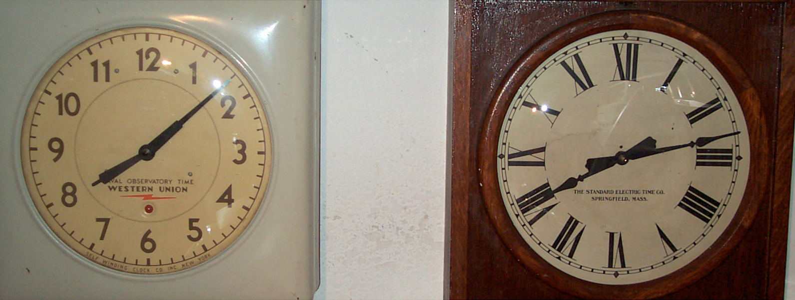
7 July 2007 - I now have a couple of clocks running side by side. One is a Self Winding Clock Co. "Western Union" pendulum clock and the other is a Standard Electric Time Co. slave clock that gets it's 1 Pulse Per Minute from a quartz crystal based circuit. As I'm writing this the pendulum clock is 3.5 minutes slow and the quartz based clock is 5 minutes fast. They were both set at about the same time when they both were adjusted for rate. This demonstrates that although a crystal has the potential to be a very good timekeeper a simple implementation may not be any better and can easily be worse than a pendulum clock.
A Quartz Watch Time Base Monitor - from RF Design magazine, maybe 1989 - uses a piezo transducer to listen to the 32,768 sound and an op amp/filter then a PLL to get a square wave so the period can be measured.
The Aging of Bulk Acoustic Wave Resonators, Filters and Oscillators by John R. Vig and Thrygve R. Meeker 1991
This paper discusses the possible aging mechanisms. As of 1991 the best aging rates that can be found are about the same as were possible using 1960s technology. Note that the best possible aging rate of a crystal oscillator depends on it's surface area to volume ratio. Therefore lower frequency crystals have lower aging rates. This is why the 32,768 Hz watch crystals have such good aging specs.
Heathkit Crystal Calibrator
Radios made prior to the introduction of digital synthesizers typically used an LC (inductance capacitance) controlled oscillator as the tuning element and did not have the ability to tune to a station directly, you needed to tune up and down the dial until you heard the station. To help find stations a crystal calibrator could be used. It generated harmonics spaced by the 100 kHz crystal frequency and when you heard the harmonic yo know you were tuned to some multiple of 100 kHz.
Easy to adjust by listening to WWV and zero beating the calibrator.
The crystal is in a CR-50/U Crystal Unit. (Tuning Fork Reference 5, page 490)
Sulzer
This design shows up in the book "Evolution of Naval Radio-Electronics and Contributions of the Naval Research Laboratory" (NRL Report 7600, January 1976) on page 289 is a photo showing the Sulzer labs unit at the top of the Omega nav receiver rack as a major improvement in crystal oscillator technology. It has a cylindrical shape and uses a proportional oven control coupled with a large thermal mass. This was a big improvement over the prior art which used bang-bang type temperature control and low mass. The crystal frequency was 2.5 MHz and it was the first all transistor frequency standard.
2871356 Frequency-stabilized oscillator, Peter G Sulzer, 1959-01-27, -
3158821 Oven for piezoelectric crystals, Peter G Sulzer, James Knights Co, 1964-11-24, - Plugs into tube socket, screw plug on top for adjustment
3287658 Frequency standard, Peter G Sulzer, Tracor Aerospace, 1966-11-22, - double oven with crystal in inner over and oscillator in outer oven.
HP
The Sulzer design was the basis of the HP 105 crystal oscillator and the cylindrical crystal oscillator used in many HP time and frequency products. HP used a 5 MHz crystal for all their versions. This is a fairly large and heavy unit.
Gibbs
This unit used a double proportional oven surrounding a Bliley glass enclosed 10 MHz crystal. The inner oven is set at the turnover temperature of the crystal to minimize the effect of any temperature change. By plotting the oscillator frequency vs. temperature you can find the sweet spot. The size and weight of the complete oscillator assembly (excluding the power supply) was much smaller and lighter than the Sulzer design.It was designed so that the lead acid batteries were in the same rack space as the double oven crystal oscillator. The acid fumes etched the PC boards inside the oven and it died. I removed the batteries, and rebuilt the boards. It ran for a few more years and I learned a lot about precision crystal oscillators. I have replaced the old double oven unit with a new Stanford ResearchSC-10 crystal oscillator. It has both mechanical trim as well as external electrical frequency control.
The power supply uses two 723 based voltage regulators in series. The first converts normal 120 VAC mains power down to about 20 volts to charge 3 each 6 Volt gel cell batteries. The battery voltage goes through another 723 based power supply that drives the heaters and electronics using separate circuits. When the mains power fails there is no switch over since the batteries are always feeding the final supply. When the mains power comes back on the batteries charge. If the blackout lasts too long a relay will disconnect the batteries to prevent battery damage from over discharge.
Stanford Research
My Gibbs got to where it was not economical to repair and was replaced by the SC 10 crystal oscillator.
Stanford Research was founded and still is based on physics rather on electrical engineering. For me, their products offer very good value and performance for the money. The SC 10 has both mechanical coarse frequency setting and a number of different options for how the electronic fine tuning will work.By adding a printed circuit board that Radio Shack used to sell that has a number of decades of division the 10 MHz output can be divided down to a 1 PPS signal. This can be compared to the 1 PPS from a GPS receiver. At this time SA was turned on and the 1 PPS had about 100 nS of random jitter (although there was always one sat with SA turned off).
Quartz Crystal Resonators and Oscillators for Frequency Control and Timing Applications by Rakon
Rubidium
The Rb and Cs "standards" are not absolute, they are just like a crystal in that their frequency needs to be set. What they offer is a lower aging rate i.e. they are more stable.Stanford Research Systems PRS10 Rb Source with built in time tag & GPS lock plus extensive RS-232 communications for only $1,495 is single qty!!!
TrueTime Inc - has a broad line of timing products, they are in Santa Rosa, near my locationCesium
HP 5060A Cesium Beam Frequency Standard Option H21
FTS 4060 Cesium Time and Frequency Standard option S24
Theory of Operation -
Interstate Electronics, Cesium Beam, Freq-Std Buffer, Part No. 7292000, Serial No. 10, Contract No. APL 601951-L
This is a group of three independent amplifiers, two have 1 input and 1 output and the other has 1 input and 2 outputs. Although they are labeled as 5 MHz, 1 MHz & 100 kHz, they work very well from below 100 kHz to 30 MHz. The gain is near 0 dB and is good for input levels up to +15 dBm input. The BNC-f input and output connectors have isolated shells and the amplifier circuit used Mini Circuits Labs transformers on the outputs. Has built-in 110 VAC power supply. Power connector is MS3106A-10SL-3S (same as the 24 Volt connector on the PRC-104 battery box). Pin "C" is ground and A&B are line for this instrument. An LH0002 IC & MCL T2.5-6 is used for each output. I think this unit was surplused because the labels indicate that it will not operate at 10 Mhz, but in fact all the channels will operate at 100 kHz through 30 MHz.
The Allan variance is a statistical measure of the stability of an oscillator. The slope of the Allan variance vs. sampling time plot will tell you about the kind of noise that is disturbing the oscillator. The modified Allan variance adds another noise type and is preferred by some as a more inclusive characterization. Typically Allan variance is measured on 1 PPS type of data using a time interval counter that has no dead time, i.e. it measures every tick. The data is stored in a computer and then processed with different decimation intervals.A similar characterization can be done in the frequency domain. There has been a lot of high powered math done demonstrating that the Allan variance information in the time domain can be converted back and forth into the frequency domain called phase noise.
Counters
Lets look at two counters:
1) A classical 1 second gate time frequency counter can display "10,000,000" (8 digits or 1E-8 resolution) for a 10 MHz input. If you want 12 digits of resolution then you can extend the gate time (assuming the time base is of adaquate stability) to 10,000 seconds (2h 46m 40 seconds, or 1E4) and can set the decimal point to display the frequency as "10,000,000.000,0" (1E-12 resolution).
2) If a Time Interval Counter is used that has 0.1 ns one shot resolution then making a measurement of the time interval between the unknown oscillator and a reference oscillator that's better you can see 1 part in E-10 in one second or to see 1E-12, like in the above 10,000 second test, it takes only 100 seconds.
The first counter only needs to be able to operate at 10 MHz. If the first counter was used in the time interval mode (i.e. counted an internal 10 MHz clock gated by the START and STOP inputs) it would have 0.1 us one shot resolution. To get that down to 0.1 ns one shot resolution the internal clock singal would need to be 1,000 times faster or 10GHz. Real counters don't use 10 GHz oscillators but make up the difference by being very cleaver. In any case you can see that a counter that has faster one shot resolution is a better counter.
On an Allan plot the first counter has a point at 1 second with a stability of 1E-8. A line can be drawn through this point with a slope of -1. The line will for example go through a point at 1E-12 at 10,000 seconds. So you can see that although it can make a measurement with a resolution of 1E-12 the counter only has a stability of 1E-8.
The second counter has a point at 1E-12 at 1 second. Again a line with slope of -1 can be drawn.
In both cases you can only measure at or above the line representing that counter.
A measure of the stability of a counter is it's true one shot resolution when measuring the Time Interval between two pulse trains each of which is at 1 PPS and the counter reports all of them (i.e. the dead time is short enough that no pulses are missed).
The stability of a counter is different than it's resolution.
The Plot
The plot is done on Log-Log paper. The Y-axis is the stability in seconds (higher stability is a lower number and is at the bottom of the scale) and the X-axis is the time interval between two points in seconds. When testing crystal and atomic standards it's common for the X-axis to run from 1 to 100,000 (1E5) seconds since the minimum interval is the time between measurements and for a 1 Pulse Per Second signal (1 PPS) that's 1 second. If the Time Interval data comparing a house standard's 1 PPS output with a Device Under Test's 1 PPS output for 1 day the max X-axis value would be 86,400 seconds, rounded up is 100,000 seconds.
For crystal oscillators the left edge of the z axis will be much shorter than 1 second.
The Slope
One of the nice features of the Allan plot is that the slope of the curve gives you some idea of what's causing that stability.
-1
For example if the line is sloping down and to the right with a slope of -1:1 you are seeing the effect of the longer time between the start and stop pulses. In the case of a frequency counter when the gate open time is increased by a factor of 10 and the result is divided by 10 the resolution improves by a factor of 10. One point on the plot would be the resolution on the y axis and the gate time on the x axis. The next point would be to the right a decade and down a decade, i.e. the line has a -1 slope. So averaging or using longer gate times does not really change the quality of the measurement but it does allow you to apply whatever quality of measurement you have at different x axis locations.
This is an important concept for many reasons.
Overlaying Two Plots
Say one plot is made using an atomic standard vs. a specific GPS receivers 1 PPS output. The plot looks like a -1:1 slope straight line starting out much worse than the crystal oscillator and ends up better than atomic standards.
The other plot is made comparing a crystal oscillator with an atomic standard. The x-axis for an oscillator usually starts some decades faster than 1 second. A bathtub shape is typical where the bottom is reached around the 1 second area and the slope is positive by 100 seconds.
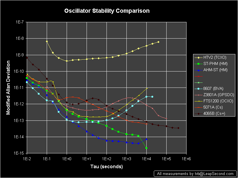
When the plots are overlaid you can see that they intersect at one point. For intervals less than the intersection x value the crystal oscillator has superior performance and to the right of that point GPS has better performance. By using GPS to control the long term frequency of the crystal oscillator the performance of the combination is better than either one by itself. This is called a GPS Disciplined Oscillator (GPSDO) and is a product made be a number of companies and there are a number of hobbyist kits to roll your own.
The Time Interval Counter
When making the Time Interval (TI) measurements a counter is being used. A classic way to do this is as follows. The Start input enables a gate and each cycle of the reference oscillator is totaled until the Stop input closes the gate. The frequency of the reference oscillator determines the One Shot Resolution (OSR) of the measurement. If the reference oscillator is 10 MHz then the OSR is 100 ns, 100 MHz is 10 ns, 1 GHz is 1 ns. A 10 MHz counter can be built easily using common logic ICs. A 100 MHz counter requires selected parts and careful circuit layout and might be classified as beyond most hobbyists ability to design. Yet TI counters are available that have a OSR in the tens of ps (0.020 ns). Needless to say they do not use multi GHz reference oscillators, but instead they use a number of clever methods. One such method is the Time to Digital converter (Google it).
If the OSR is 10 ns and a 1 PPS signal is being measured then that's a point on the Allan plot for the TI counter. A line with a -1:1 slope can be drawn through this point to define the lower test limit of this TI counter. This counter can only measure things that are above it's line, i.e. have a worse stability.
If you look at the Allan plot for something and superimpose the line for your counter on the plot if any part of the plot is below your line, then you need to use a better counter to make that measurement.
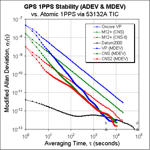
The design of the TI counter that's used for a GPSDO has a big impact on the overall performance of the combined unit. The first generation Motorola VP Oncore GPS timing receivers have a sawtooth error a little bigger than 50 ns so a TI reference frequency of 20 MHz would be in the ballpark. But the current GPS timing receivers have a sawtooth error less than 10 ns and when corrected more like 3 ns so now a ballpark TI reference frequency of 350 MHz is needed if the overall design is going to be near optimum.
I have the feeling that sometimes the measuring equipment is limiting the results of a test. This can be seen by plotting the -1 slope line for the counter on the Allan plot for the result. While surfing Allan Variance papers I came across a number related to Wavelets. The language they are using and for example the example of modling the weather makes me think there is some Chaos Theory involved. (Google: Chaos theory, Glick, fractal) (Wiki: Chaos Theory)
Time Interval Metrology Enterprise - Allan's web page - The Allan Variance (brief overview) -
Agilent (HP) app note 1289 The Science of Timekeeping (pub# 5965-7984E) <- very good coverage of Allan Variance
USNO - Clock Performance and Performance Measures.
Hamilton Technical Services - stability software and a number of on line papers
Stable32 - Techniques for Frequency Stability Analysis - extensive linked bibliography
NIST - An Introduction to Frequency Calibrations - good overview of Offset, Stability, Allan Deviation
NIST - Fundamentals of Time and Frequency - good overview
NIST - general interest time and frequency publications -
Extending the One Shot Resolution of a Time Interval Counter
Interpolators
One of the first methods is based on analog interpolators. Assuming that the input start and stop signals are asynchronous with the internal clock there will be a START to rising clock edge error and there will be a STOP to rising clock edge error. By starting a ramp generator with START and stopping the ramp generator with the next rising clock edge that time interval can be measured by a voltmeter. In a similar manner the STOP to rising clock edge error can be measured. These two corrections can now be applied to the integer count.
I&Q Sine & Cosine
By using In phase and Quadrature phase versions of the internal clock to generate pure sine waves then using a sample and hold circuit to capture the value on both channels at START and again later at STOP you can figure out the angle between 0 and 360 degrees. Where 360 degrees is the period of the internal clock So, using the above 10 MHz internal counter as an example if the votage measurement is good to 14 bits then the one shot resolution is improved by about 16,000 times, i.e. from 0.1 us to 6E-12.
Time to Digital Converter
These are ICs that use gate delay times to measure time intervals into the ps range but have a max time interval limit that reauires a slower TI counter to make up the interval to get to 1 second.
Meta Stability
There is a specification for a flip-flop that says it will not work properly unless the time between signals exceeds some setup time. But if the signals happen to arrive too close together the operation of the flip-flop can be wrong (it just hangs for a long time). So in the above schemes the flip-flop used for the gate needs to be protected from this problem. There are parts called Synchronizers that will do this.

 The
Time & Frequency Division of NIST maintains atomic clocks that
are set from USNO observations. Has a page for radio station
WWVB (60 kHz) and another one for WWV & WWVH (2.5, 5, 10, 15
& 20 MHz). There are a number of other quality pages at
this site. Their primary focus is on stable Frequency
whereas the USNO is concerned with Time. Atomic Web
Clock -Java clock showing both computer & Nist time
The
Time & Frequency Division of NIST maintains atomic clocks that
are set from USNO observations. Has a page for radio station
WWVB (60 kHz) and another one for WWV & WWVH (2.5, 5, 10, 15
& 20 MHz). There are a number of other quality pages at
this site. Their primary focus is on stable Frequency
whereas the USNO is concerned with Time. Atomic Web
Clock -Java clock showing both computer & Nist time
 The
PTTI is an organization that has meetings and publishes papers
related to time and time interval.
The
PTTI is an organization that has meetings and publishes papers
related to time and time interval.
The
IEEE Ultrasonics, Ferroelectrics and Frequency Control (UFFC)
Society has annual meetings, publishes a periodical and
papers. This page also has a large number of links.
The National Earth Orientation Service was organized to coordinate, collect, analyze, and distribute data from the various operational U. S. programs that monitor variations in the orientation of the Earth. It serves as the Sub-Bureau for Rapid Service and Predictions of the International Earth Rotation Service
Brief
History of the Development of Ultra-precise Oscillators for
Ground and Space Applications by Norton, Cloeren &
Sulzer
 IERS was created in
1988 by the International Union of Geodesy and Geophysics (IUGG)
and the International Astronomical Union (IAU). It replaced the
Earth rotation section of the Bureau International de l'Heure (
BIH ), and the International Polar Motion Service ( IPMS ). It is
a member of the Federation of Astronomical and Geophysical Data
Analysis Services (FAGS ).
IERS was created in
1988 by the International Union of Geodesy and Geophysics (IUGG)
and the International Astronomical Union (IAU). It replaced the
Earth rotation section of the Bureau International de l'Heure (
BIH ), and the International Polar Motion Service ( IPMS ). It is
a member of the Federation of Astronomical and Geophysical Data
Analysis Services (FAGS ).
![]() Frequency Standards Lab - The Frequency Standards Laboratory houses
the National Aeronautics and Space Administration's (NASA) Lead
Center for Frequency and Time. The Laboratory supplies NASA's Deep
Space Network (DSN) with the hardware, expertise and technology
for state-of-the-art frequency standards, clocks, distribution
networks, and time synchronization to enable deep space navigation
and advanced radio science experiments.
Frequency Standards Lab - The Frequency Standards Laboratory houses
the National Aeronautics and Space Administration's (NASA) Lead
Center for Frequency and Time. The Laboratory supplies NASA's Deep
Space Network (DSN) with the hardware, expertise and technology
for state-of-the-art frequency standards, clocks, distribution
networks, and time synchronization to enable deep space navigation
and advanced radio science experiments.
on eBay with patent dates. Although the clock is labeled
General GE Electric, all the patents are for the Warren Clock Co.
|
1283431
Electric-clock system, Henry
E Warren, Warren
Clock Co, 1918-10-29, - fly-ball regulated steam engine powered AC generator powers master and slave clocks. Standard pendulum clock set from Navy time signal. Fast or Slow button pressed to control motor that fools fly-ball governor to offset output frequency. The slave clocks have a backup movement (45) that is held stopped by arm and ferrous metal core (50). If the AC power fails the core is released allowing the backup movement to start. No provision for setting the slave clocks. |
||
1334422
Electrically-driven clock, Henry
E Warren, Warren
Clock Co, 1920-03-23, - Mercury switch on
pendulumCites: |
|||
| 1430867
Lubricating system, Henry
E Warren, Warren
Clock Co, 1922-10-03, - |
|||
| 1456082
Motor drive, Henry
E Warren, Warren
Clock Co, 1923-05-22, - |
|||
| 1495936
Motor drive, Henry
E Warren, Warren
Clock Co, 1924-05-27, - |
|||
| 1546269
Self-starting synchronous motor, Henry
E Warren, Warren
Clock Co, 1925-07-14, - |
|||
| 1615664
Clock movement, Henry
E Warren, Warren
Clock Co, 1927-01-25, - |
|||
| 1768386
Motor rotor, Henry
E Warren, Warren
Clock Co, 1930-06-24, - |
This clock displays a new four letter word once each 10 seconds
and the time for 10 seconds starting at the top of each minute
based on a GPS receiver. The time is underlined (Fig 5).
Fig 1 EATS |
Fig 2 PERK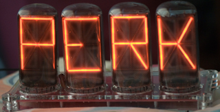 |
Fig 3 OVAL |
Fig 4 SPIT |
Fig 5 11:10 |
Fig 6 WOGS |
Fig 7 WHOA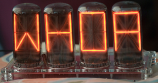 |
Fig 8 KEEL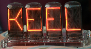 |
Fig 9 TYPE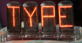 |
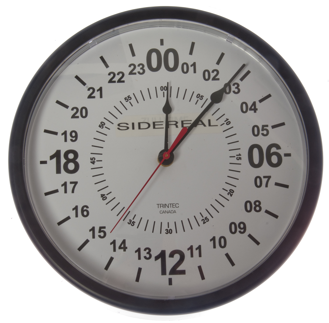
| Sidereal
Wall Clock Dec 2014 Made from a 24 hour quartz wall clock by adding a "Crazy Clock" module with the sidereal option. |
 |
| Kundo ATO Electric Clock A very efficient clock, hence on the Joule Thief web page. |
 |
page created 30 Jan. 2000.


