Dent Meridian Instrument - Dipleidoscope
 |
 |
 |
 |
 |
 |
 |
 |
 |
 |
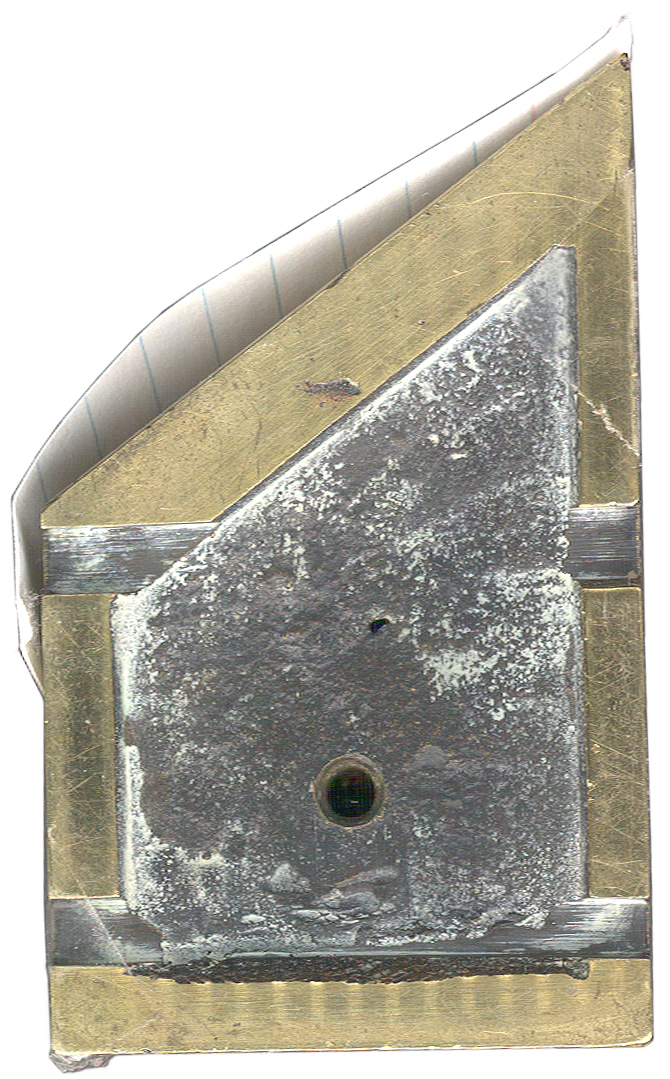 Bottom w/3x5 card on face |
Description
Operation
Patent
Steinhell Transit Prism
Roelofs Solar Prism
Solar Attachments
Related
See Also
Reference
Links
Background
In 1843 Bloxam patented a Meridian Instrument as Great Britain patent No. 9793. Bloxam brought his design to Edward John Dent (Wiki) who was an instrument maker and as a team they put the design into production. This instrument is very similar to Figure 12 through 19 in the patent. Dent's instrument manufacturing business is now called Dent London. They are the company that built the clockwork for Big Ben (Wiki).
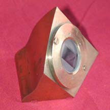
Description
The manual mentions that when working with the Sun three measurements should be made. When the two images first touch each other, when the two images are congruent and when the two images are again just touching. By making three observations some error correction can be done and also this method allows for missing one of the observations maybe due to clouds.
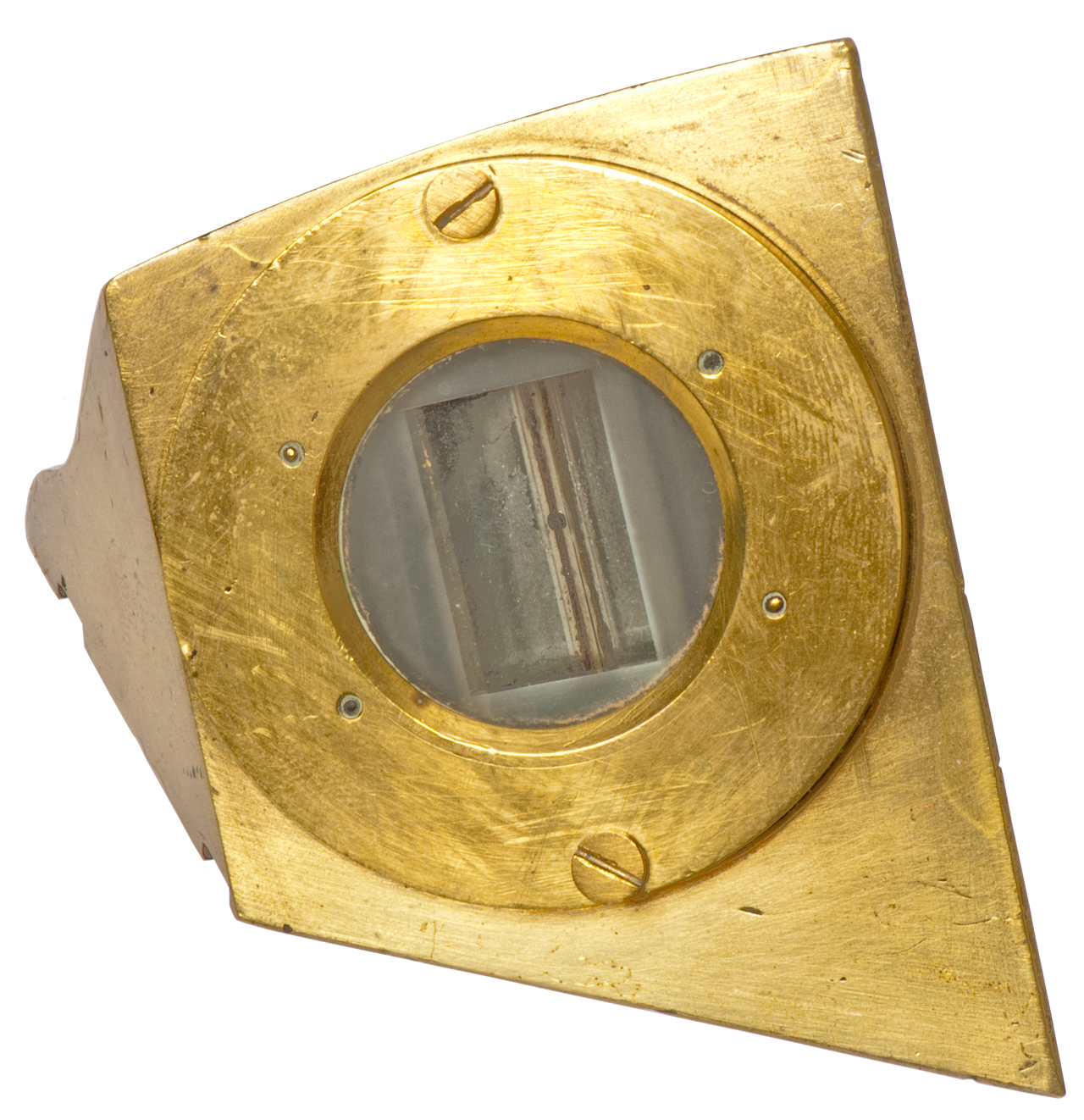
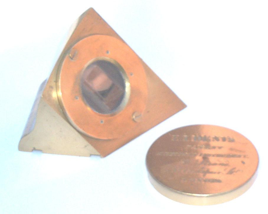
The instrument is made from a Brass casting and is a little less than 2.5" high. There are a couple of notches on the bottom a little more than 0.2" wide and about 1.25" C-C as well as a tapped hole that loosely accepts a 10-24 screw but is probably some British Standard thread. The notches and tapped hole would allow the Dipleidscope to be fixed in rotation.
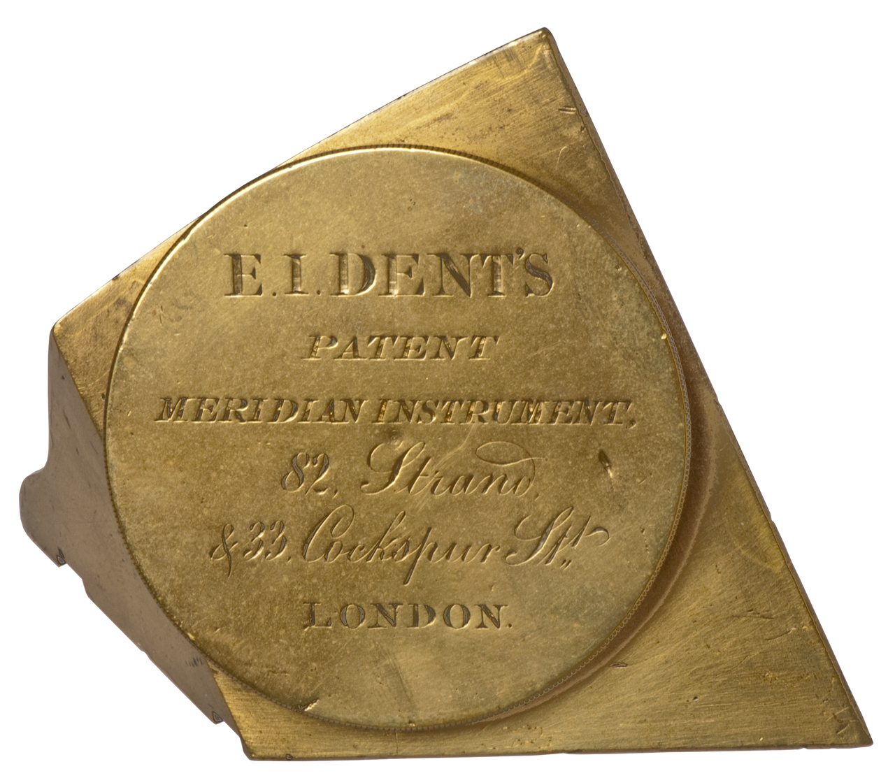
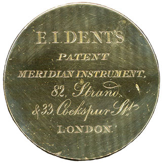
The cap is engraved with the following:
E. I. Dent's
Patent
Meridian Instrument,
82, Strand,
& 33, Cockspur St,,
London
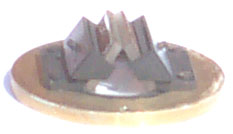
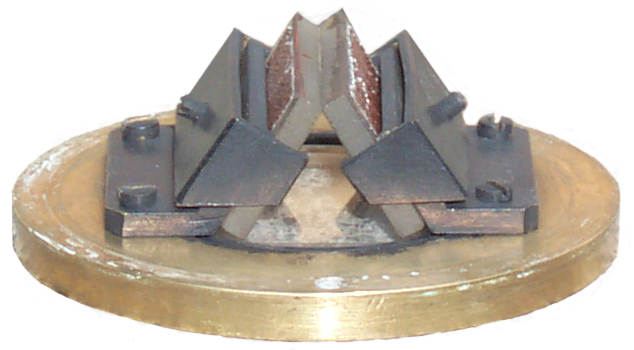
The two mirrors are rear surfaced, not front surface types. They are held in place by a set screw that presses on a metal plate that has raised lips at the ends so the mirror is clamped at it's ends. The angle between the mirrors is set by how the support brackets are machined and is not adjustable.
Operation
There is an image that is produced by light reflecting off of both mirrors, this image stays still as the instrument is rotated about the common axis of the mirrors. To find this image you need to move your eye relative to the instrument. The other image is formed from a single reflection off of the cover glass, this image rotates as the instrument rotates.
It is difficult to look at the Sun's image directly, both because it's bright but also because someone has polished the instrument to show off the Brass, but the original instrument was painted flat black.
It can also be used as a reflecting ceiling dial, but to do so requires some type of mounting.
Patent
US patent class 33/269 is Geometrical Instruments/Straight Line Ray Type - Celestial - Time Computing.
Reference
A Description of the Dipleidoscope, Or Double-reflecting Meridian ..., Volume 7 By Edward John Dent
Solid Dipleidoscope Prisms C.V. Boys - instead of using two mirrors.
Royal Museums Greenwich - Dent instrument with magnetic compass and time scale
The Museum of the History of Science: Dipleidoscope, by E. J. Dent, London, c. 1870 -
Post on the Sundial Yahoo Group by Mike Cowham:
"The request for patent information sent me immediately to the booklet 'A Description of the Dipleidoscope...' by Edward Dent 1843, a copy of which was supplied with his dipleidoscopes. It does not give the patent number, but one picture of the device E. I. DENT'S PATENT MERIDIAN INSTRUMENT giving the address 82 Strand & 33 Cockspur St.
The Postscript makes interesting reading and I have included it below. I made a few photo copies that were sold on the BSS Bookstall at Dunchurch last year. If any more are required, I will make them available for a donation to the BSS of 1.50 pounds each. Anne Somerville will be proud of me.
+ + + + + + +
POSTSCRIPT
The origin of the Dipleidoscope resulted from the following circumstances. The writer had long felt persuaded that the interests of Horology would be promoted if the public were more generally possessed of a cheap, simple, and Correct transit-instrument, requiring little or no scientific knowledge for its right use, and not readily Susceptible of injury or derangement. To this end he had devoted much time and thought; and, in 1840, he considered that he had succeeded in inventing an apparatus which, by means of shadows, would produce the desiredresult. This idea he communicated to J. M. Bloxam, Esq., who thereupon informed him that his own attention had been for some years devoted to the same object, and that he had contrived an optical arrangement, which, by the agency of a single and double reflection, determined the sun's passage over the meridian with great exactness. When the optical instrument, although complicate in its then form, was shown to the writer, he was immediately struck with the superiority of the contrivance over that which had suggested itself to him: his own method afforded three observations, but it was attended with the defects and inconvenience which result from the uncertainty of shadows. Convinced that the reflecting planes would effectually accomplish the desired end, he entered into an arrangement with Mr. Bloxam to undertake their manufacture; and, after nearly two years' attention on the part of that gentleman, and at great labour and expense on the part of the pro poser, they are now respectfully presented to the public in the present simple, but most accurate form. The writer, to secure his property in the instrument, as well as to insure its future perfect manufacture, solicited the favour of Mr. Bloxam to take out a patent in his own name, at the expense of the manufacturer, and, for a certain consideration, to transfer all interest in the invention to him. This request was kindly acceded to, and accordingly the Dipleidoscope, as an article of commerce, bears on it the name of the maker and proprietor, E. J. DENT.
Regards,
Mike Cowham.I & I News No. 12, 5 July 2013, pg 3: The dipleidoscope by Bill Barton.
Illustrations taken from free on line Dent publication "Dent on The Dipleidoscope: Double-Reflecting Meridian and Altitude Instrument"
YouTube: What Is This Thing? Nobody Realized What It Was For! — Part #33 - @2:58 Dent of London -
Steinhell 1847 Transit Prism
Learned about this on a post in the Antique Telescopes Forum with the subject line: Stump the astronomers on 2024 Aug 22 by Rich S.
This meridian instrument by Steinhell was a few years after Dent's 1845 meridian instrument. It has a number of ease of use improvements.
Not shown, but necessary is a target type bubble level to allow the two adjustable feet to plumb the vertical column.
This is similar to leveling a surveyor's transit or theodolite.
The tangent screws allow setting the azimuth to the meridian.
The elevation angle can be set for whatever object is going to be observed.
The right angle in the telescope makes viewing much more comfortable.
Height: 24 cm. Diameter of base. 10 cm.
Mfg: Plössl & Co., Wien (Wiki: Vienna)

Roelofs Solar Prism
This is an attachment for a theodolite that allows finding North by centering the sun in the telescope and knowing the precise time.
The old way was to use a solar filter and then position the sun so that it was in, say, the upper right quadrent and touching both the vertical and horizontal cross hairs. But this means the telescope is not aimed at the center of the sun, but rather off to one side and that requires corrections.
The Prism works just like a kaleidoscope (Wiki) and causes four images of the sun to appear in the telescope. Now the sun is actually on the centerline of the telescope when the four images are centered on the cross hairs.
1501979 Optical instrument, Arthur H Brooks, 1924-07-22, - cited by 2506037.
used to aim at the sun.
"Fig 5 is a magnified view of the image of a circular object having a semi-diameter equal to the angle of deviation of the prism, formed by the prism and object glass in the plane of the focus of the object glass in the plane of the focus of the object glas which is indicated by the line 4-5 in Fig 1."
The markings on the patent may mean there was some legal action about it.
2506037 Solar attachment for theodolites, Roelofs Roelof, 1950-05-02, -
DE803487 Additional device on a theodolite to facilitate pointing the telescope at the sun, Roelof Roelofs, 1951-04-02, - looks to be the same as 2506037.
2759393 Optical aligners employing axicons, John H Mcleod, Eastman Kodak, 1956-08-21, - patent is not for Axicon, but rather for an application of it.
"The Axicon: A New Type of Optical Element,” Journal of the Optical Society of America, 44, pages 592-597, August 1954.
All axicons are, at least approximately, figures of revolution. They have the common property that a point source on the axis of revolution is imaged by the axicon to a range of points along the axis. This image is real but is not a definitely focused one in the sense of an ordinary objective or lens image. Axicons do not have a definite focal length; apparent exceptions to this rule will be mentioned at the end of this specification. The name axicon is derived from "axis image.' Axicons will form images only of small bright sources like lamp filaments or brightly illuminated pin holes. The image is in general just a point image, but a filament of special shape will be imaged so as to have that particular shape.
A problem of long standing in optics has been to provide a telescope, such as for a transit, that will focus for close distances without having to move any parts. The objection to moving parts is that they disturb the alignment of the optic axis, at least sufficiently to disturb the adjustment of a precise instrument. According to the present invention optical aligners are made up using axicons so as to overcome this problem.


Solar Attachments
There are many patents with "Solar Attachment" in the title that are about a device allowing the sun to be sighted with the attachment on a transit telescope.
The idea is that the position of the sun in known for a given date and time. Typically the attachment is set so that the telescope points South when the attachment is pointing at the sun.
Related
Dent's Portable Registering Tell Tale - Night Watchman's recording clock (added 11 April, 2017)
See Also
Astro-Compass Mk II
Astronomy
Navigation Orientation & Position
North Finding
Polarized Skylight Compass
Stellar Time Keeping
Surveying
Theodolite
Ukiah, California Latitude Observatory
Links
Back to Brooke's Products for Sale, Navigation, Sundials, Time & Frequency, Military Information, Home pagePage created 21 March 2003