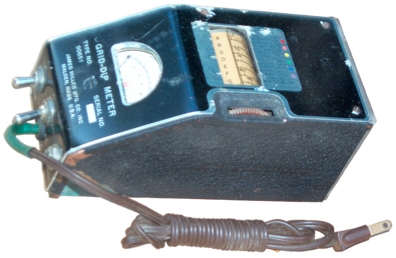
Millen 90651 Grid Dip Meter
© Brooke Clarke, N6GCE,
2003 - 2026
Background
The Grid Dip Meter aka Grid Dip Oscillator uses a
meter in the grid circuit of a tube to sense the loading on
oscillator tank circuit. When the frequency of
oscillation is adjusted to that of a nearby tuned circuit the
grid current dips, hence the name. Since it is both a signal
generator and a signal detector it can be used in many
applications.
This Grid-Dip Meter can be used with it's line cord, or
batteries (6 Volt A and 67 to 135 Volt B) can be used for
power. There is a Plate Voltage switch on the front
panel so that the oscillator function can be turned off so the
tube can be used as a detector.
The line cord on this unit appears to have never been undone
and the small paper UL tag is still on the cord.. Maybe
this is a New Old Stock unit?
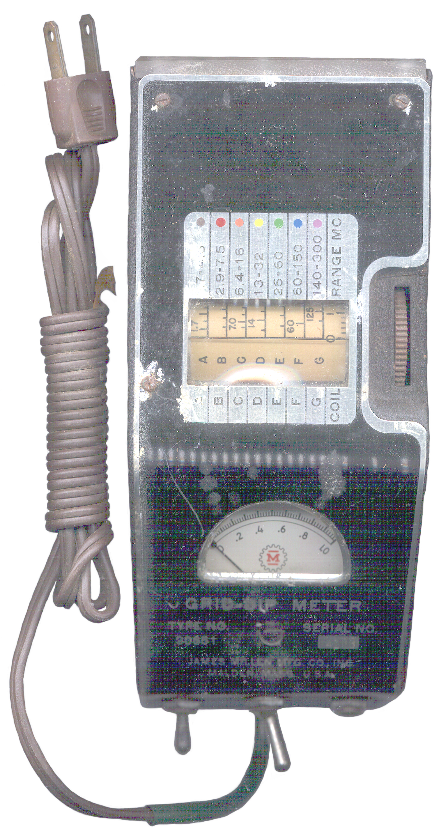
Ranges
Band
|
Start
Mc
|
Stop
Mc
|
Color
|
A
|
1.7
|
4.5
|
Brown
|
B
|
2.9
|
7.5
|
Red
|
C
|
6.4
|
16
|
Orange
|
D
|
13
|
32
|
Yellow
|
E
|
25
|
60
|
Green
|
F
|
60
|
150
|
Blue
|
G
|
140
|
300
|
Violet
|
Coil Log
|
0
|
10
|
-
|
Manual
The manual has a number of applications for Grid-Dip
Meters in general. The topics covered are:
Section I General
- Grid-Dip Oscillator
- Oscillating Detector 0 use external headphones with 1/4"
mono plug
- Signal Generator
- Tuned R.F. Diode or Non-Oscillating Detector - Plate
turned off
Section II Methods of Coupling
Figure 1 has a number of cases.
Section III Applications
- Receiver Tuned Circuits
- Transmitter Tuned Circuits
- Neutralization
- Parasitic Oscillations
- Parallel Reasonant Traps
- Series Reasonant Traps
- R.F. Chokes
- Measure Circuit Q
- Relative Q at given frequency
- Measurement of Capactance
- Measurement of Inductance of R.F. Coils
- Relative Q of Capacitors or Inductors
- Antennas
- Tuned Reasonant Feeders, as used in Zepp Antenna
- Untuned or Non-reasonant Feeders
- Tuning the Parasitic Beam
- Quarter-Wave Shorted Lines
- Quarter-wave Open Lines
- Half-wave Shorted Lines
- Half-Wave Open Lines
- Check Standing Waves
- Relative Field-strength Meter
Section IV Power Supply
Has information on how to connect batteries.
Section V Ground
The 90661 has a 3-wire power cord, but the 90651
has a 2 prong A.C. cord.
Section VI Maintenance
Has some minimal troubleshooting
information. But remember that the circuit is also
minimal.
Section VII Low Frequency Use
Lists the optional coils for 325 kc to 2,000 kc.
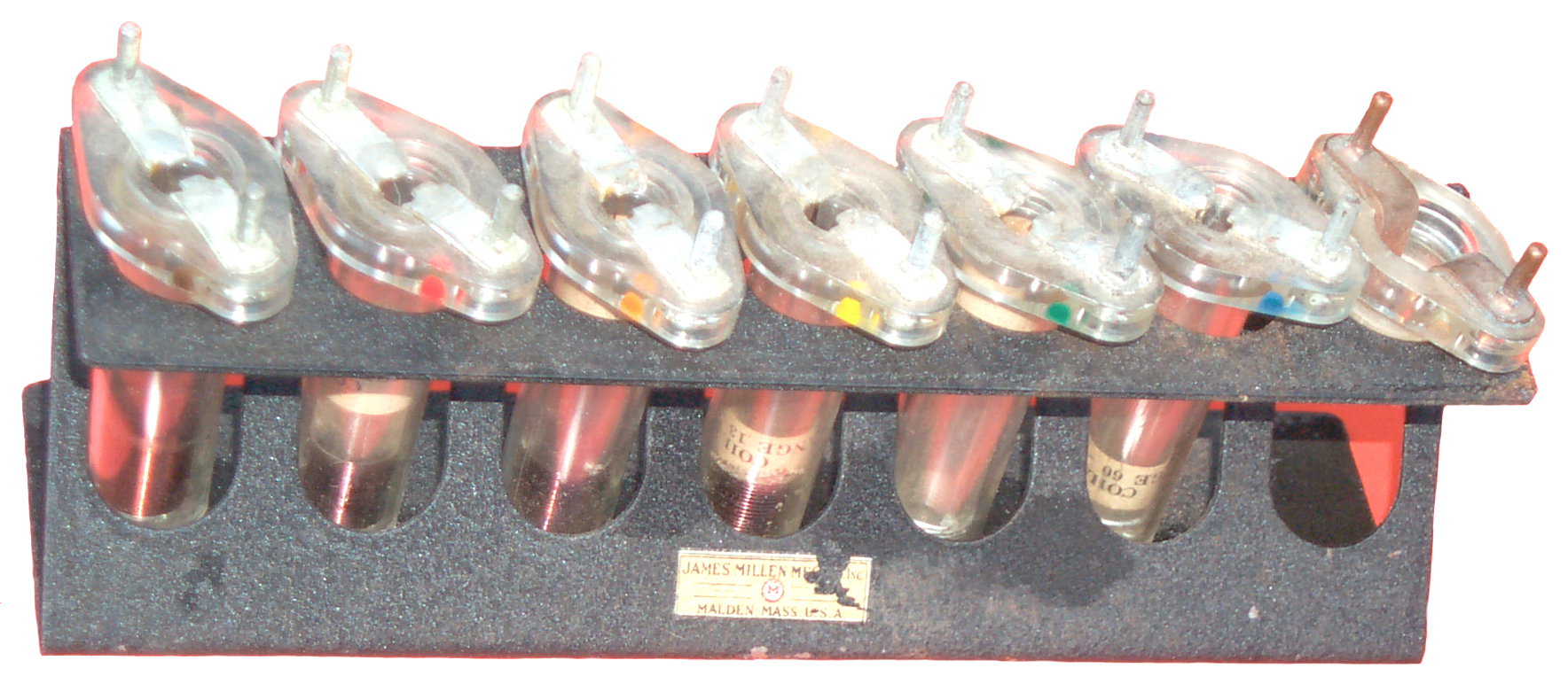
Section VIII Coils
Seven coils are standard and cover 1.7 to 300 Mc.
Note: You can make your own coils and a couple of 6-32
screws will fit into the coil sockets.
Section IX Technical Summary
Basic specifications.
Schematic Diagram
Capacitor Test Fixutre & Equations
Graph showing Dial reading vs. Frequency for Low Frequency
Coils
Capactance Calibration Graph
Parts List
Order
Manual as 21 page pdf document with 4 photos added
to end. The text has been OCRed and appears as text, not
images, making it much easier to read. Can be printed on
8.5x11" paper.
The origional manual was stapled at the top and then folded
into an 5 ½ x 8 ½ size.
See the product page for
ordering information.
Page created 10 Oct 2003.