Manuals Scanned by Brooke
I have scanned some manuals. These are NOT on my CDWM and are only sold seperatly. They appear on the web pages associated with their subject matter. These are done one page at a time on a flat bed scanner with optimum exposure control and page backing to eliminate bleed through on the adjscent page. Cleaned of blemishes where possible and aligned to within 0.3 degrees of square. Schematics are stiched onto a single page just like in the origional manual so can be printed using the Acrobat tiling feature (requires full Acrobat, not reader). Table of Contents has links to page numbers and page numbers referenced in document are linked.
HP 4332 LCR Meter - no OCR
care and adjustment of K&E Surveying Instruments -
Leroy Lettering and Symbols -
K&E 1949 41st Edition Catalog Part 2: Surveying Equipment, Field Books, Measuring Tales (outdoor stuff) -
1928 K&E Illustrated Catalog complete including Price List - Extensive links for navigation
Another advantage is that as battery technology advances the most common cell sizes see the new technology, like the current advances that are taking place with "AA" cells. By using a battery adapter you can get the benefit of these new technologies much sooner than with specialized batteries.
Battery Top Power Supply (12 Nov 2005)
This is a working prototype of the Fixed output voltage type. This one has an LM2936-5.0 regulator and it reads 5.00 volts. This regualtor has very low Iq (on the order of micro amps and so will not drain the battery when there's no load connected. Budgetary sell price $8.50 including s/h and CA sales tax.
The PCB has a couple of pads for soldering wires that have a narrow trace conneting them. So if you want to add an On-Off switch when using regulators like the 78L05 that have an Iq of a few milliamps, it's easy to do.
This is a working prototype of the Variable output type. It has an LM317L regulator. With the current resistor values the voltge can be set between 1.25 and 7.7 volts very easily (25 turn pot) to within a millivolt.
The LM317L would be more useful when used with 3 batteries ( 3 * 9 = 27 Volts fresh and about 14.4 volts flat). Also the 3 battery configuration would work for 12 and 15 volt supplies. Note that negative versions are not needed since you can wire two positive versions back to back to form a bipolar supply, like for op amps since the batteries have seperate grounds.
I have a couple of current projects that require a 5 Volt battery type supply. These are for magnetic field sensors that will be used outdoors away from the house. They should be regulated supplies, not just raw batteries. In one case the supply needs to be small (like on the top of a 9 Volt battery.
This is a Printed Circuit Board with a couple of caps and a +5 voltage regulator IC that snaps onto the top of a 9 Volt battery. The PCB is about the same size as the top of the 9 Volt battery so that the combined battery and power supply can be installed in small project boxes. In addition to the TO-92 regulator I first looked at, there are a number of other TO-92 regulators that have different specs and prices. The 9 V battery snaps are also used on the 68BA battery adapter (above)
Let me know if you're interested.
May 2006 solder mask & Silk-screen Prototypes here
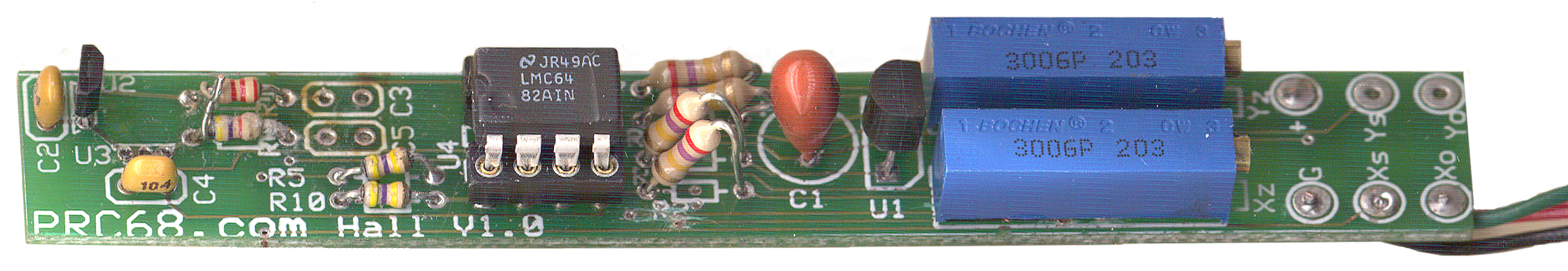
- 2-Axis Hall magnetic sensor. ( 0.525 x 3.76 inches) Narrow PCB so it will fit into a zero gauss chamber. Includes
two pots for zeroing the initial offset and dual high quality op amp to increase the scale factor to at least +1 volt to -1 volt for earth's field. Includes voltage reg. Two outputs from each sensor, raw and amplified. The amplified will be offset corrected. The raw output allows measuring larger fields (depending on which Hall sensor is installed). Also can be used as a 1-axis sensor with double the sensitivity.
This circuit has problems. The layout program can fool you. It shows gaps between vias and adjacent traces, but if the gap is too small (less than 0.007 inches) then there may be a short on the actual board. Tried to fix these by trimming the vias. There is an oscillation, although the DC output meets specs. Probably caused by the poor layout. An improved version now working on a white protoboard that incorporates filtering along with the amplification of the sensor signal.
Photo shows first unit which works.
- Battery Top Power Supply both (0.71 x 1.05 inch) Fixed output and Adjustable output versions.
- Battery Top Signal Generator, Frequency Synthesizer-Translator, Test Transmitter, (Crystal Replacement?).
The calculator says you will get 51.010689 MHz from a 6.144 MHz DIP oscillator and the spectrum analyzer says it's 51.010625 MHz, not bad.
The 6.144 MHz DIP oscillator was not a good choice since it is a music top ocatve frequency and does not have a lot of factors. The 16.6666 MHz DIP is a much better input source because it has a lot of small prime numbers when factored, see the Crystal Frequencies web page.
A first look at the spectrum analyzer shows the harmonics and spurs down 50 dB, but that may be a function of the input and output frequencies, way too many to test all of them.
Prototype CLose Up.
(2.7 x 1.5 inch) Based on the ICS525. Has 14 pin socket wired to accept either a half size or full size DIP oscillator and a jumper option to use the DIP oscillator or the input on a BNC-F connector as the 525-02 input. Output on another BNC-F connector in the 1 to 250 MHz range. Includes 9 volt battery snaps and on board Voltage regulator or solder two wires to the marked pads for an external power supply to drive the LP2950A-5.0 low drop regulator.
On line 525-02 calculator. Provides an output square wave in the 1 to 200 Mhz range with about 2^19 possible different frequencies. If they were equally spaced (they're not) the step size would be about 380 Hz. Two 10 position DIP switches to set frequency.
- For use as a crystal replacement a short coax cable to go from the BNC output to a couple of pins that match the crystal socket would be needed. In addition a L-C filter and/or attenuator may be needed to clean up the signal. If a divide by 10 IC was put at the output of the 200 MHz part it would bring the upper frequency limit down to 20 Mhz and decrease the step size to about 38 Hz. Dividing by a higher number may be better since most crystals have a fundamental frequency lower than 20 Mhz. Crystals higher than something like 5 MHz are odd number overtone types and since the output of this circuit (either stock or with a post divider chip) is a square wave, it's already rich in odd harmonics and even though the fundamental frequency was low.
The ICS525 only comes in a 28 pin SSOP package that has 0.025" pitch. In order to solder this part to the PCB I'm getting professional SMT soldering equipment.
The ICS525 is the basis of a ham radio fox hunting transmitter (Canada). UK Fox hunting Tx 525 based.
The data sheet says the max output frequency is 250 MHz, but the equation for output frequency is Fout = Fin * 2 ((V+8) / ((R+2)*S) so setting V+8 = 24 and R+2 =2 and S=1 with a 16.6666 MHz input gives 400 MHz out and that's what I get. With spurs each side spaced by 16.6666 MHz. But when set for 51.0 MHz out the spurs are spaced by 1.375 kHz and the VCO input is 1.6666 MHz, why?
- TVB divider - (3 x 1.65 inch) PIC based frequency divider. Includes voltage regulator. Typically used to divide the output of a precision oscillator down to 1 PPS to allow time interval measurements.
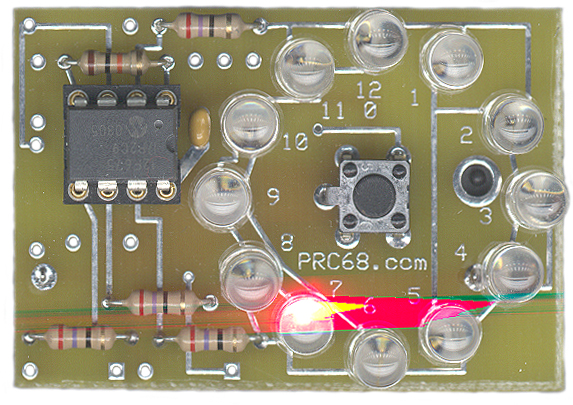
29 April 2006 - The prototype works after a couple of bug fixes. I will be going out for beta test. It's hard to see in the flash photo, but the Green LED is on, Red LED is off and the Yellow LED is blinking. The next board will be smaller but retain all the features of this one.
To the right of the two ICs are three red jumper wires. I have these set so that Aout is 1PPS, Bout is 1 kHz and the Yellow LED is 10 Hz. The idea with the 10 Hz LED is that you know in a tenth of a second if the chip is working (if you disconnect the Clock input the uC stops). Any longer period and you need to wait one period to know. If any faster then your eye would could not tell the difference between a locked uC and one that's running, so 10 Hz is about optimum. At 1 PPS the wait needed is noticeable.
- Two BNC-F inputs: (1) Clock for the PIC, typically 10 Mhz and (2) Sync input uses Stop button and Red and Green status LEDs.
- Two selectable BNC-F outputs choose from 100 kHz, 10 kHz, 1 kHz, 100 Hz, 10 Hz, 1 Pulse Per Second, 10 Seconds, 100 sec or 1,000 sec when driven from 10 MHz. Third LED can be connected to any of the above outputs as heart beat indicator.
The output driver is a hex 74AC04 with three outputs going to the Aout BNC and three going to the Bout BNC.
- The PCB layout is based on using an 18 pin PIC like the 16F84 that the above assembly code was written for, but comes with a different PIC in a socket. So if you want to try your own code to do different things it's easy to change micro controllers.
Paper Design
High Brightness LEDs
These are the LumiLED that started out with the 1 Watt emitters and the current third generation K2 units are 3 watt. The "warm white" type is available in a small number of packages. National Semi makes buck mode Switch Mode Power Supplies for each of these so that they could be powered from a 12 or 24 volt DC power source.
Precicion Clock #4
Description
The idea is to allow adding a clock to a precision frequency standard, like the FTS4060 or any standard that has a 1, 5, 10 MHz or 100 kHz output (maybe also a 1 PPS or other frequencies). The frequency standard is used as the clock source for a 16F88 (or maybe larger) PIC micorcontroller. The display includes hours, minutes and seconds on the first line of a 16x2 LCD and Day of Week, 4 digit year, Month in three letters, and day of month.16 Feb 2007 - Have working three terminal piezo sounder that uses an external oscillator circuit. The circuit can be powered directly from a PIC pin at 5 volts and the sounder makes quite a bit of noise. It's the most noise for the power input in the piezo types and in the magnetic types that can be driven from a PIC pin directly. I'm hoping that if a very short pulse is fed to the oscillator circuit a tick sound can be made.
An important aspect of this clock is that it keeps on ticking during the setting process. This way the 1 PPS output edge is maintained. This is very different from conventional clocks that stop during the setting process.
In the 1950s Timex ran a series of TV ads showing their watch suffering some torture and then we were shown the watch face and heard the slogan "takes a licking and keeps on ticking®" was what John Cameron Swayze would say. The important thing is to keep ticking. Jewelers would not sell the "cheap" watches that had no jewels so instead the Timex was sold through drug stores. Now Timex is the largest producer of watches in the US.
In a move to increase the chances of getting the design complete the following has been removed: 12 hour mode, am/pm, time zones, backup clock (the back up clock may come back).
The following are planed for
- Synchronization to an external 1 PPS input and/or the ability to adjust the 1 second edge.
- Clock Fail Detect. Note that only the fairly recent PICs have this ability. The 16F84A for example just stops if you remove the clock input. Being able to switch the instruction clock source in software also allows the clock to be started on the internal RC oscillator which has advantages over depending on the external clock.
22 Dec 2006 - When thinking about making the Precision Clock the main task seemed to be to get it to work. But now that the electronics is working the main task seems to be getting a packaging design. Years ago I wrote Rocky Mountain Basic programs to control microwave test equipment and were completed and put into use. But then I would be called to the production floor because the "program is not working". It would turn out that a cable was missing, disconnected or bad. So the programs were rewritten with a lot of error diagnostics so that the operator would be told why the system was not working and the operator could fix the problem. This error reporting was a much larger effort than just getting the program to work.
I've spent most of the day looking into different sizes and types of Liquid Crystal Displays. But being at the start of the Xmas holiday people are not answering their phones, maybe next week or next year I'll get some answers.
19 Dec 2006 - I'm working on the packaging and have purchased a number of commercial enclosures, but they all leave something to be desired. If you have an application that would have implications on the packaging please let me know.
21 Nov 2006 - There's a limited amount of board space so it may make sense to have two seperate products.
5 Oct 2006 - The allowable input frequencies (user settable at power up) are 2.5, 5, 10 or 20 Mhz.
- One is the clock calendar for use with lab standard frequency sources. It does not need a backup RTC but it would be good to have RS-232 both for reading GPS to set the clock and to output the time + date along with a 1 PPS output.
- Another is a battery powered Precision Clock based on a RTC and using a lab grade standard frequency source or a timing GPS grade 1 PPS to train the RTC.
28 Sep 2006 - after removing the code in the ISR that handles checking for clock fail and the code for moving the 1 PPS edge there's still a problem with navigation at 1 Mhz. the Day of Month field is impossible to reach and sometimes the field that's selected changes when no button is pressed.
27 Sep 2006 - Now when DC power is applied the clock comes up in a menu to allow selection of the input frequency (here the instruction clock comes from the internal RC oscillator and so no external clock is required). This worked well for 10, 5 and 2.5 MHz but not for 1 Mhz and 100 kHz. It soon became clear that the problem is that as the input frequency is reduced the time for each instruction to run increases and when the time needed for the Interrupt Service Routine (ISR) to run gets to be a significant part of 1 ms (the ISR is called every 1 ms) then there are problems. So I've been thinking what to do. My internal debate has been weather to slow down the rate of the ISR, use different rates for different input frequencies, or not support 100 kHz and maybe 1 Mhz.
Today my thought is to keep the ISR at 1 ms for all input frequencies (this has a number of advantages) and eliminate the code in the ISR for moving the 1 PPS edge and move that code outside the ISR by doing it a different way so as to minimize the number of instructions in the ISR (there are a number of other tricks that can be done to shorten the ISR). That will probably allow 1 MHz operation and preserve the 1 ms ticks. As I woke up this morning an idea of how to move the 1 PPS edge without changing the milli second counter became clear, thus allowing that code to be removed from the ISR yet still allow the edge to be moved.
Knowing what you want is the hard part. It's taken a couple of days to understand what the problem was at 100 kHz and an additional couple of weeks to figure out what to do.
9 Sep 2006 - Clock Fail is working. If the input signal (5 Mhz today) is removed the time freezes and the HH:MM:SS and YYYY MMM DD display fields blink. After (but not before) the input is reconnected if either Left or Right is pressed for a few seconds the blinking is turned off and the PC4 returns to using the external clock input. Of course the time and 1 PPS edge are now wrong and this has been made clear to the operator. A few layout bugs have been fixed on the prototype PC4 boards.
 7
Sep 2006 - The four navigation and set buttons are now working with
the new wiring where the LCD data bus is serving also for reading
the buttons. This frees up the 2 (and maybe 3) PIC pins
that were being used for buttons and now can be used for the back up
clock. It takes only a very short amount of time to set the
time and date.
7
Sep 2006 - The four navigation and set buttons are now working with
the new wiring where the LCD data bus is serving also for reading
the buttons. This frees up the 2 (and maybe 3) PIC pins
that were being used for buttons and now can be used for the back up
clock. It takes only a very short amount of time to set the
time and date. |
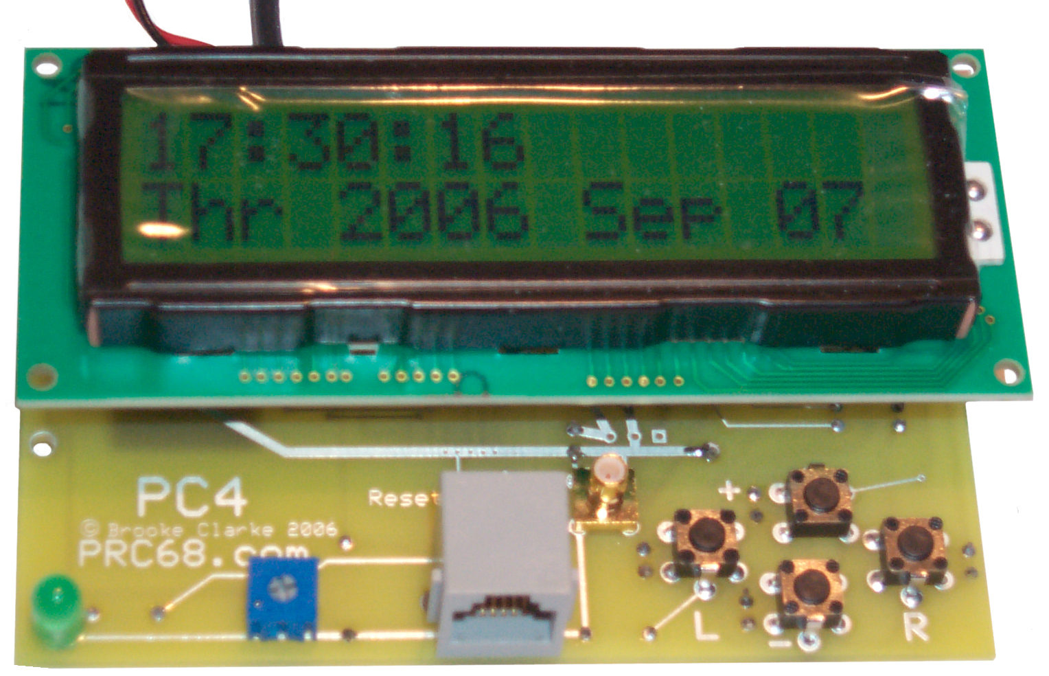
25 Aug 2006 - First printed
circuit board for PC4 turned on working with the old
code. Since all the ICs are surface mount ICD2 is
being used for both programming and debug which required
some cleverness to share the PIC pins. The form factor
is not the final version but instead is the low cost 2.5" x
3.8" standard "MiniBoard" service that has more area than
the final board. For this board the heartbeat LED, LCD
contrast control, ICD2 connector, 1 PPS output connector and
the 4 navigation buttons have been moved to be below the LCD
rather than beside it. These are all mounted on the
"back" of the PCB and the ICs are mounted on the "front" so
that there are no parts between the LCD and the PCB.
The two pads with the label "Reset" are for the backup real
time clock IC. Now there is no need for the "->" or "|" characters since the Left and Right buttons are always for navigation to a different field and the + and - buttons are always for incrementing or decrementing the highlighted field. Reading the buttons is interleaved with updating the LCD and they share PIC pins. |
 |
16 pin LCD socket at top. 1 PPS LED at bottom left then LCD contrast pot, ICD2 jack that also has the 1 PPS input that might be used for the SYNC function. SMB jack for 1 PPS output, and the 4 navigation switches. This is really the "back or trace" side of the PCB. But is the side seen by a user. |
 |
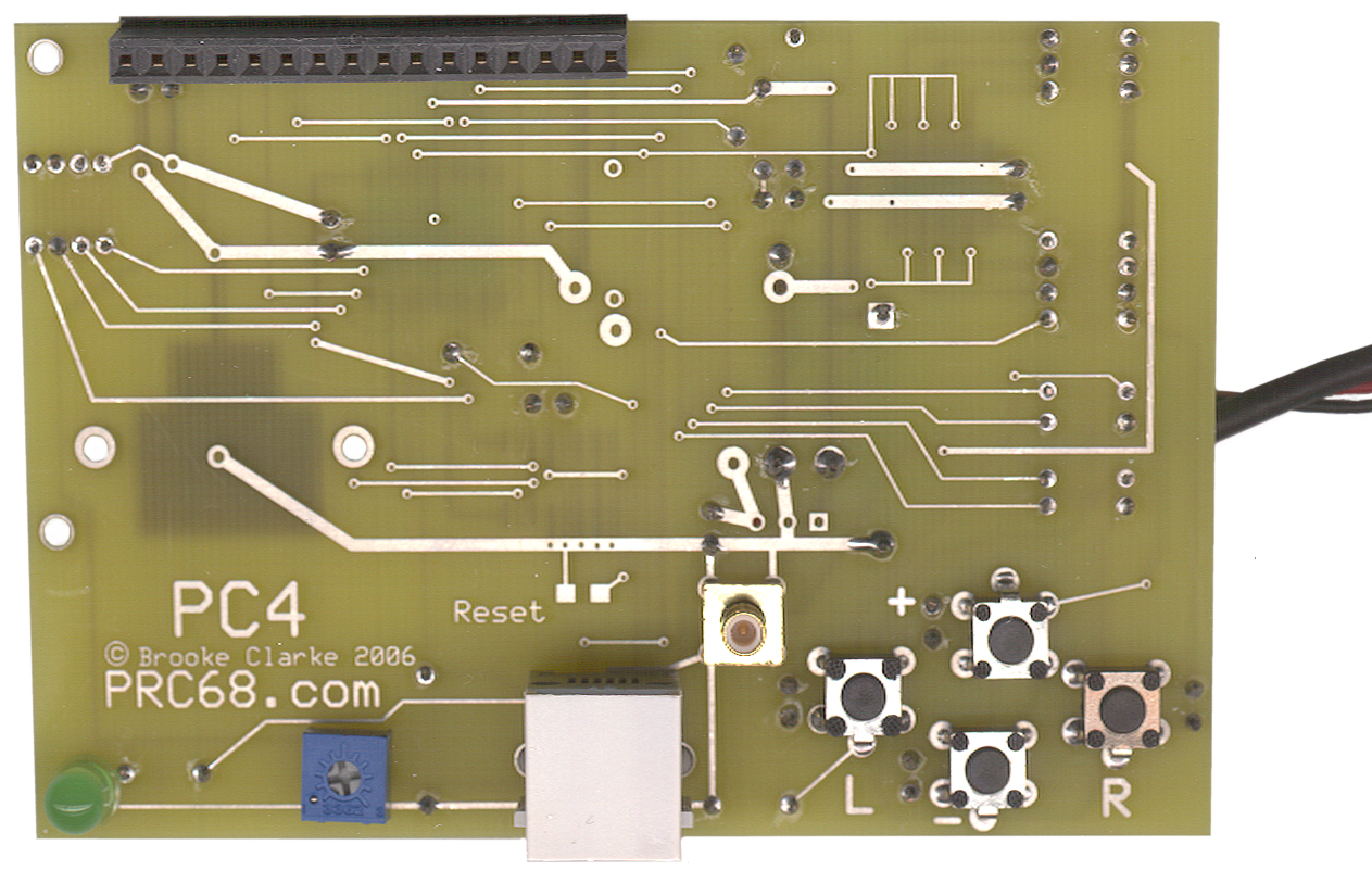
Small IC on left is 1 PPS driver and the larger IC is the PIC 16F88. The real time clock IC (missing SOIC package) and it's backup battery have not been installed. Also the resistor on LCD pin 16 for the LED back light has not been installed. This resistor provides backlight power from a seperate supply so that a power failure will turn off the backlight and allow a backup supply to keep the PC4 running. The third level backup is the RTC which will run from a button cell battery for a very long time. |
24 Aug 2006 - Have detection of external clock failure and automatic switch over to internal RC clock working. To indicate that there's been a failure of the external clock the display blinks HH:MM:SS & YYY MMM DD. When the external clock returns the PC3 does not switch back to using it and keeps blinking.
Printed circuit boards are on order for PC4 that will have 4 buttons and a backup 32768 clock.
20 Aug 2006 - Mechanical layout shows that the PC3 circuitry will fit the board space and that it may be possible to use 4 switches for navigation (making the setting operation much more intuitive) and add the backup 32768 Hz real time clock and maintain the functionality of ICD2 while staying with the 16F88. This level of functionality might be called the PC4 (PC3 for the 3 switch version and PC4 for the 4 switch version with backup clock).
The circuitry for the averaging Time Interval Counter (TIC232) will not fit the board as an addition to the clock. This circuit requires that the PIC have an internal gate on the Timer1 input (which most PICs do not have) or that an external gate is used. It would make a very nice companion to the Precision Clock and may be the next project. But instead of only allowing for use with a PC serial port an LCD and push buttons would allow manual use of the counter in addition.
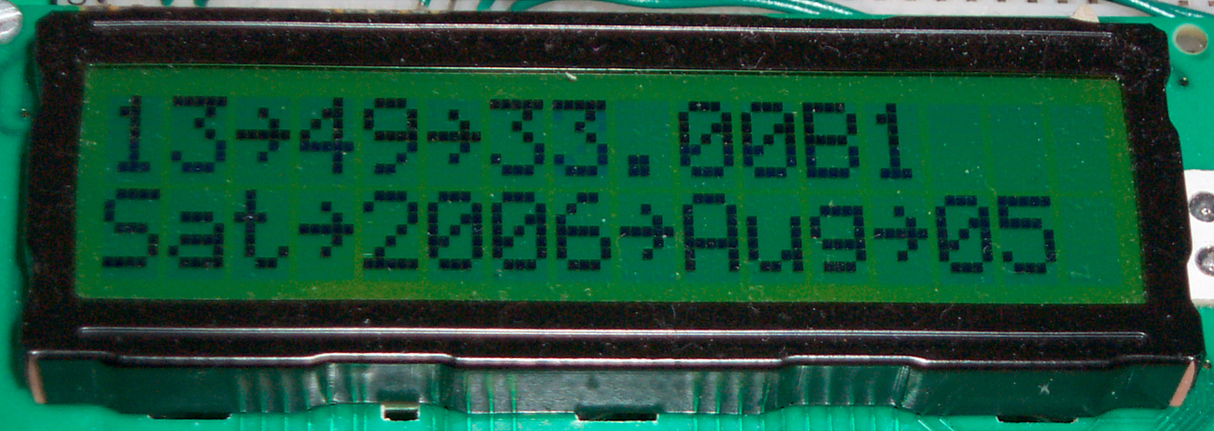
11 Aug 2006 - have 1 PPS output edge adjustable in 1 ms steps. When in Navigation or Set mode a decimal point and 4 hex characters are visible, and when the left or right navigation buttons move the flashing field to the fractional part of a second it can be incremented or decremented to move the 1 PPS edge. The first line is showing: 13-> 49-> 33.00B1 where 00B1 is the hex character for the 1 ms step 1 PPS edge adjustment. The "->" symbol between fields indicates the clock is in navigation mode so pressing the buttons will move the focus to the left or right. When "|" shows between fields pressing the same buttons will increment or decrement the data in the blinking field, but with no rollover to other fields.
5 Aug. 2006 - Now have Zeller's Congruence working for Day of Week for any date in the Gregorian calendar (from 1582 AD) and to go with it leap year tests using Year/4, Year/100 and Year/400.
26 July 2006 - The software blink navigation is working and the bugs that created in the leap year and DOW routines has now been fixed. Starting to work on a leap year routine that uses the 100 and 400 year tests in addition to the simple 4 year test. It's strange that after all the to do about Y2K that these routines would not be common. Next will modify the display so that a ":" is used to seperate both the time digits into groups and also the DOW:YYYY:MMM:DD groups in the Display mode. When in Navigation mode they ALL will change to "~" or some other horizontal type symbol and when in Increment/Decrement mode to "|" or some other vertical type symbol, to make it easy to tell what the current mode is. The clock can now be set to within a second or two very quickly. Note that when changing the seconds they are counting so rather than trying to get the display to a fixed value what you do is calculate the difference between the clock display and the correct time and then push either Increment or Decrement that many times without really paying attention to the display. This "blind" approach will get you to within a couple of seconds. Then by comparing the display to the actual time the last second can be resolved.
But at this point neither the Synchronization feature nor the setting of the 1 PPS edge are operational so the seconds are not ticking over on the UTC edge.
23 July 2006 - Have the new software blink navigation working for left or right in Navigation mode and transition into and out of Set Mode.
A short press of the Select button moves you from Nav mode to Set mode or from Set mode to Nav mode. The first ":" changes to "s" when in set mode or to "n" when in Nav mode. The field blinks to indicate the focus of the change (not set since the clock is running during this procedure). Next will change the construct of how incrementing is done in the maintenance of the counters to allow decrementing also. Since decrement is very handy for changing (setting) the time and date it also would allow a count down mode for the clock.
22 July 2006 - Reworking the navigation method to use software controlled blinking instead of the hardware blink. The software blink gives a better looking display and you have more control.
21 July 2006 - Have the Navigation buttons working for Increment (left), Select and Right (decrement) data. This allows setting the clock, but it's not friendly since the clock needs to be stopped to allow cursor or blink to work. Need a better way, any thoughts?
18 July 2006 - The PC3 is keeping exact time now. After running a day from the cesium standard the time is correct to way better than a second so the software is using the correct divisors.
17 July 2006 - Fixed bug in clock counting code that was causing an error of a few seconds per day. Will know tomorrow, but after an hour any error is less than some milliseconds. It turns out that using the TAC32 audible second tick makes comparing the PC3 to GPS, WWV or WWVB clocks much much much easier since you can count along in your head. The flash of the 1 PPS LED is exactly coordinated with the "tick".
Using the K.I.S.S. (Keep It Simple Stupid) principle this clock will have no provision for time zones, no am/pm (i.e. only 24 hour format) and UTC enunciator, no alarms. I'm trying to design the packaging so that it will work both in the 5.25" single height drive bay and also on the front panel of the FTS4060 above the monitor meter.
16 Jly 2006 - have tested the calendar for key dates, like 29 Feb 2000, 21 Sep 1998 (the test date in the Day of the Week app note TB 028, today, and others and they all check out.
Today have started to confirm that the clock is keeping time. The easiest way to start is to just set it (now done by setting the starting time in the program and unplugging and then plugging in the clock input. This is within a second and if 41 min 40 seconds later the time is still within a second (the first time the clock was off by 1/250, a counter preset programming error) then the software is probably good. For this test I'm using the FTS4060 with it's 1 MHz output as the heartbeat and a WWV clock as a reference.
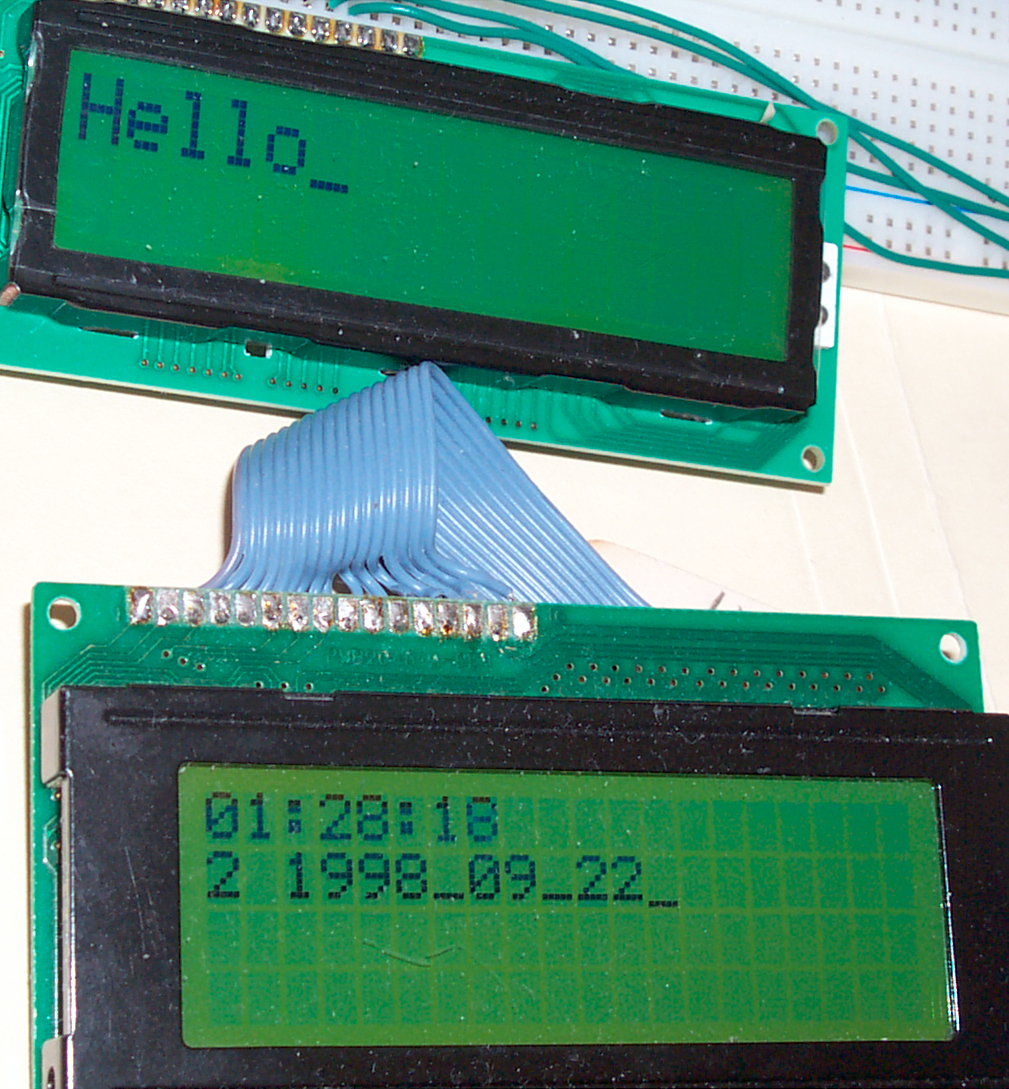
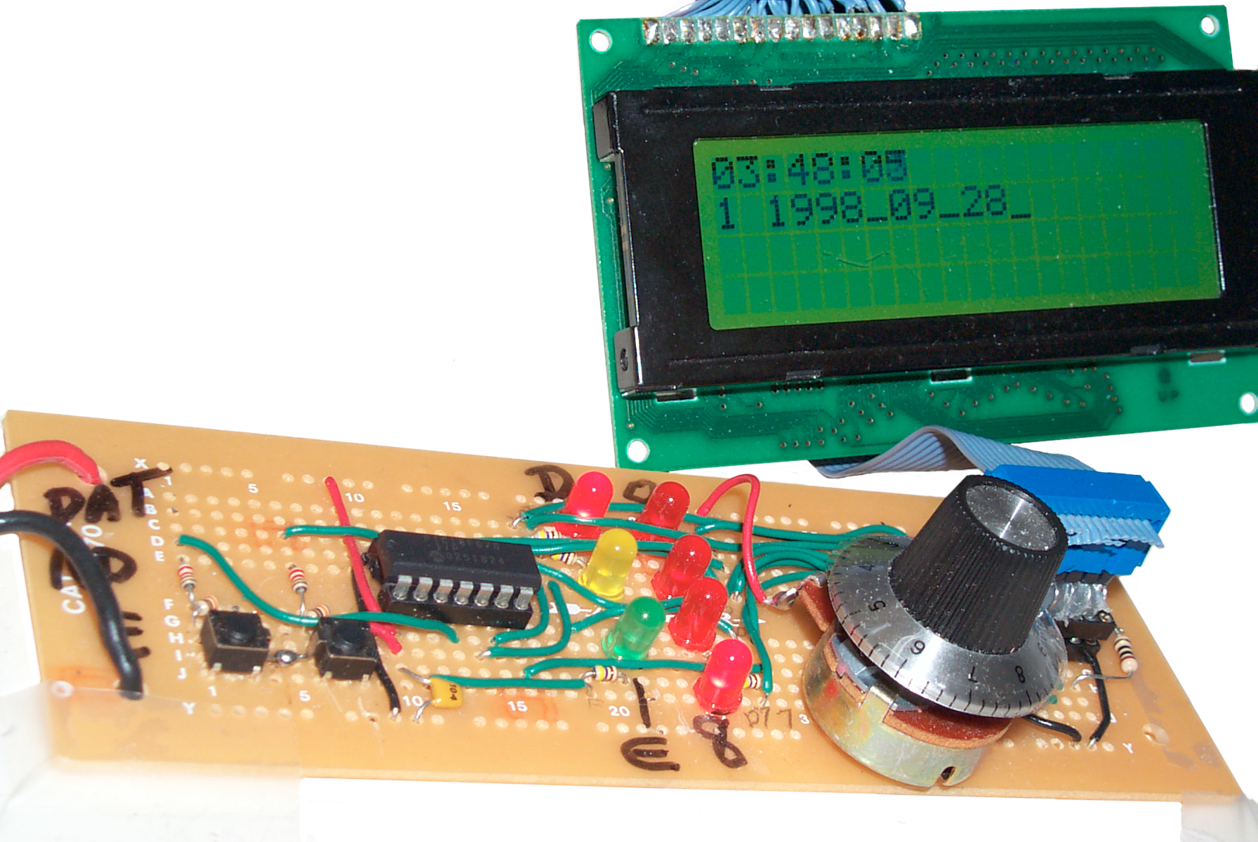
7 July 2006 - The 16x2 Display (top of photo) that's targeted for the PC3 has much larger characters than the 4x20 (bottom of photo). The 16x2 is being driven from a 16F88 using new LCD driver subroutines taken from the PIC Demo2 software package and the 20x4 is driven from a 16F676. These drivers read and write a bit at a time to control the LCD and in that way do not disturb the other bits on the port that are doing other things. But still not using the Linker software, just one assembly source file.
Different web pages give the viewing distance for the 16x2 character height of 7.78mm (0.3055") as between 5.5 feet to 15 feet. Without reading glasses I can easily see the display at 8 feet (not convient to test further) this both with a desk lamp on and off(back light always on).
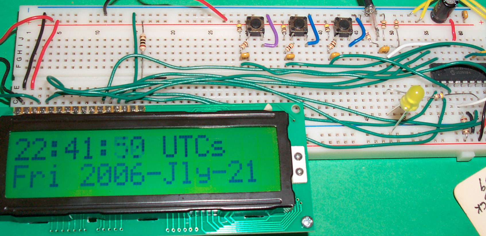
25 June 2006 - 16F676 proto of PC3 driving an LCD and keeping track of and displaying HH:MM:SS and DOW#-YYYY-MMM#-DD. But have run out of RAM registers and need to move to a much larger PIC, probably the 16F916 in a 28 lead 0.026" pitch Surface Mount Package. It has much more RAM as well as many more pins and so will support more features. Now has Microchip TB028 Day of Week routine as well a LCD navigation based on reading LCD cursor position and LCD data. Built on Radio Shack 276-170 Solder type breadboard. Still have not found all the part numbers and suppliers needed to make a dedicated PCB.
Note that the Microchip App Note TB028 Technique to Calculate Day of Week only uses the 2 digit year divided by 4 leap year test, not the 100 year exception and not the 400 year exception to the exception. The 4 year test is done using bit tests. If the lsb is a 1 then the 16 bit integer year must be an odd number and so Feb has 28 days. Then looking at the the next higher bit if it's a 1 then the year divides by 2 byt not 4 so again Feb has 28 days.
I think an easier way is to just shift the 16 bit year unsigned integer to the right 2 bits and look for a carry each time, if there is a carry quit and use 28 Feb, if not continue. To do the 100 and 400 year tests start after the 4 year test (with the two lsds already shifted). Now, using a loop, subtract a byte containing 25 from the 16 bit year integer and count the number of times the loop is used until there's a carry out of the top of the year number or until the year number is zero. If there's a carry out then the year is not divisible by either 100 or 400 and Feb has 29 days. If the year is zero then it's divisible by 100 and Feb has 28 days unless the loop count shifted right 2 bits has no carry then Feb has 29 days.
I've also found that all the real time clocks that I've looked at (in production in 2006) only use the 2 digit year/4 leap year test. So there's going to be a major problem in Y21H (Year 21 Hundred).
June 2006 - Based on the very common LCD modules that use an HD 44780 equivalent controller chip. The major advantage of these displays is that they draw much less current (under 1 ma) with the back light off, compared to an LED type clock that draws many watts when large digits are used.
Because these LCD modules are used for computer "Modding" where they are typically mounted into an empty 5.25" drive bay there are available mounting kits that have the bracket and have a membrane keypad with a hole for a common LCD module. Unfortunatly the kits are for small LCD modules, not the one I'd like to use that has much larger characters, so probably will end up making my own 5.25" drive bay mounting kit. The commonly available 5.25" single bay exteranl drive enclusures come with power supplies, either USB, external wall wart and/or mains A.C. all built in.
By making the clock on the insert bracket and by using the standard PC 5.25" power connector the clock can easily be mounted into a computer. This might be good if it's going to be used as part of an NTP server.
The display might look like:
10:23:04 PDT
Wed 2006 Jun 21
Most digital clocks only display hours and minutes becasue the internal time base is not accurate enough to keep track of seconds. The exception to this are clocks where the A.C. mains power frequency is used for the heartbeat. This clock will run from a frequency standard that supplies a precision 10 MHz as the heartbeat.
Single Axis MR type Magnetometer
On a PCB that will fit inside a PVC pipe (1/2 to 3/4" TBD). The sensor can be installed either so the sensitive axis is coaxial with the pipe or transverse. 0 to + or - Vcc/2 output or Vcc/2 + or- Vcc/2 outputs for either driving a meter or a uC. Can be mounted standing up like a SIP using a 10 pin 90 degree header.
Optimized for the widest possible voltage swing (highest resolution in a uC) by using a pot for setting the sensor serial number dependent offset to zero and another pot to allow setting the instrumentation amplifier center point to match Vcc/2. Using an instrumentation amplifier (functionally 3 op amps) instead of a single op amp allows the DC common mode signal to be canceled which is not the case when an op amp is used. Let me know if you're interested.
When used with a voltage regulator can drive a 0-1 ma meter. When used without a regulator and connected to a uC Vcc then the uC A/D can work in the ratio metric mode.
It may be possible to connect two sensors back to back with seperate battery supplies (w/regualtors) and wire the bipolar outputs back to back in series to make a gradiometer.
BA-5590 Style Battery Plug
One part that mates with either a primary or secondary BA-5590 type battery.
Custom made military style circular shell-insert but using standard pins and a size 12 shell cable clamp. No potting needed.
Commercial pin extraction tool can be used to disassemble for reuse.
29 April 2005 - have pins and clamps on order to refine drawing.
Preliminary quote from machine shop indicates it's possible.
This will support offering a number of cables for both getting power from the BA-5590 family and for charging them.
17 July 2009 Have working prototype.
NCDXF Beacon Calculator
This is a calculator that will tell you which beacon you are hearing. Need a timepiece that has seconds readout and is set to about 1 second accuracy, or can be set by tuning in a short wave time station. In beta test a contest grade CW op was surprised that he could hear partial beacon IDs because the calculator told him which station would be there where without the calculator he would not be able to ID the sending station. The calculator can also be used with 2 or more receivers in an interesting way.
14 March 2005 - Status working prototype finished. Now beta testing. Lost in hard drive crash.
Digital-Retro-Trubo-Encabulator - 26 April 2006 - Paper design in progress.
Design on back burner
Enigma-E
An Aluminum panel and cabinet for the Enigma-E electronic functional equivalent of the M-3 and M-4 Enigma machines.
No support from the developers of the Enigma-E. Project canceled.
Precision Clock
12 Dec 2004 - the PIC16F688 has the clock fail feature like the 16F684 but in addition has a hardware serial port supporting RS-232 and does all this in a 14 pin DIP package thus allowing for less PCB space and for easy manual assembly. As of this date I think this is the lowest pin count PIC with a hardware serial port.
To get the greatest flexibility the clock (and future products) should be divided into the following seperate PCBs:
15 Oct 2004 - Looking into an interface to the Z3801 GPS disciplined 10 MHz source, but need a Z3801 to see what's what. It uses PECL for some of the signals, so some differential line receivers may be needed, although PECL speed is not needed so there may be some cost savings by being cleaver. Also runs from a 4 x 12 Volt "48 Volt" supply, meaning somewhere between 40 and 60 Volts. Charged lead acid batteries would be at 54.4 Volts. The Z3801 may not like to start up below 54 Volts. This "48 Volt" supply impacts the design of the clock power supply, since it should run from the same supply that's powering the Z3801.
- Display - to fit the Jameco enclosure, includes Allegro 6276 LED driver chips. Needs inputs for LED DC power and serial data for the cascaded 6276 driver chips. Optional displays would include alpha numeric characters for date and time displays or many smaller digits for a counter display.
- Clock -has the time keeping PIC, input conditioning circuitry for 1, 5, or 10 MHz inputs as well as for a 1 PPS input, the mains based DC input is backed up by a battery based DC input and these are diode ORed.
- Power Supply - voltage regulators for the LED supply and the Clock. m If the mains power fails the LEDs go black but the clock keeps on ticking.
- Z3801 Interface - both a PECL interface and a "48 Volt" input power supply
- Oscillators - these would be PCBs designed to hold oscillators like the FEI odd frequency units, or standard oscillators like the Stanford Research 10 MHz or HP 10 MHz or other oscillators.
- 1 PPS edge Adjuster - this would be a PCB that would allow moving the rising edge of the it's output 1 PPS relative to the rising edge of it's input 1 PPS based on a manual input and would remember the delay in EEPROM.
- Motorola M12+T GPS receiver - a PCB to supply DC power, RS-232 interface, Antenna DC, backup pwr, etc.
- Motorola GPS Saw Tooth Corrector - a small PCB that would sit on top of the M12+T Motorola GPS receiver and have male and female connectors just like the M12+T so that it can be a plug and play solution. Would turn the Time RAIM message at power up.
Note that the Clock shown at http://www.realhamradio.com/dclock.htm is just a GPS driven clock and has nothing to do with the disciplined oscillator. I.e. the information is shows is based on data from the GPS receiver in the Z3801. The Precision Clock version 4 uses the disciplined 10 MHz from the Z3801 as it's heartbeat and outputs a 1 PPS based on that input. The 1 PPS output is intended for use with a Time Interval Counter.
29 Aug 2004 - Precision Clock version 4 (as in 2004) is in design. The display PCB is sized to fit into an instrument enclosure and there's enough room for a red plastic sheet in front of it. The dual power supply is on a seperate board that mounts inside. A wall wart supplies a bridge rectifier and a large capacitor. It can be driven by a large number of wall warts, either AC or DC and over some range of voltages, but it does need to supply about 1.5 amps. The low voltage power supply drives the LEDs and they go out when there's a power failure. The + 5 volt power supply has two inputs by means of a diode OR gate, either the DC from the wall wart or from backup batteries in the clock case or external to the case.
This clock uses the Allegro chips like in the version 2 clock below to drive 4 each 1" character height 7-segment LED digits for HH:MM and 2 each 0.8" high seconds digits. The input is similar to the first Precision 6 digit clock below in that it runs from a frequency standard at 1, 5, or 10 MHz or optionally a 1 PPS source. It will be mounted in an instrument enclosure. Power from a Wall wart with seperate power supplies for the digital circuits and the LEDs. When (not if) the power fails the LEDs will turn off but if a 6 Volt backup battery is installed the clock will keep going. But the frequency standard also needs to be on a back up supply. The power supply is on a seperate PCB from the front panel display-clock board. Current thinking is to use a LDO TO-220 regulator for the logic 5 volt supply and a LDO TO-3 regulator for the LED supply.
21 Sep 2004 - The PIC 16F684 has the same pin out as the 16F676, but has a Fail Safe Clock Monitor function that's not in the 16F676. Part of this is an automatic switch over to the internal RC clock on failure of the main clock. This way the Precision Clock v4 can be started without an external clock input (although it will not keep time) and more importantly it can detect a loss of clock that exceeds a couple of milliseconds, like would happen with an intermittent cable or outright failure. With the 16F676 the clock would just freeze when the clock was unplugged, but this allows the display to be flashed to indicate a problem, a much more noticeable thing. Also this allows removing the 10 MHz unit oscillator from the board which was getting very crowded. The LT1016, or one of the clones made by a number of other makers, looks like a good input IC to change about any RF signal into a nice clean clock for the PIC. Using the LT1015, which has 2 LT1016s in an 8 pin package would be good for both an RF input and a 1 PPS input.
Precision 6 Digit Clock - Is a 6 LED Digit precision clock (HH:MM:SS) where the microcontroller (uC) clock source comes from a precision oscillator at 1, 5, or 10 MHz or a 1 Pulse Per Second source. The first version will be a printed circuit board 3.8" wide and 2.5" high. Optional input frequencies will be offered such as 10.0543478 MHz.
It may be possible to offer an optional version that would display Sidereal time for astronomical use by swapping the uC for one with a different program. This version used multiplexing and the LEDs were not as bright as they could be.
Precision Clock Version 2 - Uses DC drive to the LEDs, so they are very bright.
The above Precision clock is intended for use with lab grade precision frequency standards as a way to monitor their performance. While working on the MM5369 replacement it made sense to develop a lower cost clock that would use a standard unit oscillator as its heartbeat but add corrections for the initial frequency offset, temperature drift and aging of the unit oscillator. Making these corrections should improve the accuracy of the unit oscillator many orders of magnitude. This is something I have read about in a number of places but have not seen applied.
This clock will use an 8 pin PIC and will not have any RS-232 interface. It will be on a single sided PCB to further reduce cost. 18 Dec 2002 - making temperature and aging measurements on unit oscillators from various vendors.
MM5369 Replacement - The MM5369 was an IC that used the then low cost color burst crystal to produce a 60 Hz output. The enhancd replacement will use a unit oscillator (about the same cost as a crystal and frees up one microcontroller pin). A jumper selects either 50 or 60 Hz output and there is additionally a 1 Pulse Per Second output. This has been prototyped and if there's any intrest will be made.
12 LED CLock
15 Nov. 2003 - This is a small clock that uses a unique LED display and is powered by a 123 type LiMnO2 battery, the same one used with the 5BA and 90BAv2 battery adapters. The same hardware can be used for other tasks such as counting the pulses from a rotary dial phone.
10 Nov. 2003 - Starting to work the program. The streak in photo is caused by the flatbed scanner moving while the LED is on. The missing components are for measuring temperature and battery voltage.
23 Nov. 2003 - AVI Movie showing clockwise rotation 150K Bytes. By using low resolution the speed of the rotation looks about correct. At higher resolutions the web is too slow to properly show what's going on. This is just to confirm operation and the board is sired correctly.
Dec 2003 - computer crash has stopped this project.
Design stopped not enough Demand
1500BA Battery Adapter for the Tektronix 1500 series Metallic Time Domain Reflectometer. These will not turn on if there is not a battery pack installed and the factory battery packs are no longer available, but the instrument is built to mil specs and most of them are still working fine. If you're interested please let me know.
1112BA Battery Adapter for the URC-68 to replace the BA-1112/U- First Proto using 10 "AA" batteries.
13 May 2002 - have crystals on order for operation on 223.50 MHz for ham radio simplex.
14 May 2002 - have PC board battery contact samples on order to make the battery holders.
15 May 2002 - have a rough PC board with sockets that mates to the radio pins.
10 June waiting for a small quanity of battery contacts and clips for a hand made proto (another URC-68 coming to check pin spacing)
14 June - first prototype working well. Need an idea of demand?
16 June 2002- Waiting for pricing on Xtals for 51.0 MHz operation. No Joy.
19 June 2002 - Need to modify design to allow jumper selection of either 9 Alkaline or 10 (11?) rechargable cells to get about 13.5 V total.
8 Aug 2002 - the Xtal for 51.0 MHz does not oscillate.
This will not become a stocked product like the ones above, but may be made in small lots on demand.
See the 1112BA web page if you want the 1112BA and/or the 220 Mhz ham band Xtal.
These are only ideas.
If you are interested let me know so I can gauge which, if any, should be developed.
If you have an idea for a similar product let me know.
- BA-1372, BA-5372 Battery Adapter that would a 4LR44, 28A, LR544 or similar button stack 6 volt battery.
- Hardware Random Noise Generator
The idea is to combine a diode type noise generator with a PIC microcontroller that would output random bytes on an RS-232 port that could be read by any computer or even fed to a printer. The PIC PIC16F627A-I/P has 18 pins so has higher PCB cost then the 16F688 but sells for about $2.70 in small qty & $1.53 if you buy a stick of 25. Digikey has over 7,000 in stock, so it's a more popular chip than the 16F688 ($1.97 @ 25) at this time.
Hardware RNG v1 by Roman Black based on AC mains
True random number generators, Hardware random number generators, Links & Articles by Robert Davies
NIST - SECURITY REQUIREMENTS FOR CRYPTOGRAPHIC MODULES
4355366Circuitry for minimizing auto-correlation and bias in a random number generator, NCR, Oct 19, 1982, 708/255, 331/78 - XOR
6324558 Random number generator and generation method, Nov 27, 2001, 708/255, 708/250 - Fig 14 1/f noise plot and need for AC coupling
- KY-57 mechanical replacement that could be cabled into secure voice systems. The box would have non functional knobs and would have no electrical content. Maybe possible to add CVSD digital voice with no or simple encryption.
- A battery adapter that fits the mechanical outline of the BA/BB-x90 family (BA-5590, BB-390, BB-490, etc.) battery and uses common "C" or "D" cells, but fewer than 20 becasue there's not enough room, so an active DC-DC converter is needed to bring the voltage back to 15 V Note the Bx-x90 battery is called a "2 x 12 Volt" battery, but really the voltage is 2x15.0. In process, see above.
- An adapter that uses 30 "D" cells in the PRC-74 "Wet Battery Box" CY-6121. This would replace the 10 each BB-418/U wet plate NiCads the box was designed to hold.
- BA-4386/U replacement that is the same size using "C" cells.
- Battery adapter that holds 10 each 9 Volt batteries for a 90 Volt BC-611 "B" battery to replace the BA-38. A better idea would be to use some "AA" cells and a Switch Mode Power Supply. Would cost way less to buy the batteries.
- "D" cell battery adapter to fit the CY-6121/PRC-74 Wet battery Pack or a Battery Adapter for the CY-6314
- PEWS data decoder that displays sensor number and detection mode (P and/or M) from wire or radio + data to computer
- PRC-68B, -126, -128, -136 computer data interface to allow up/down loading frequency
- Remote control head for the PRC-68B, -126, -128, -136 allowing setting frequency
- Cloning cable that works on two radios of the same type: PRC-68B, PRC-126, PRC-128, PRC-136
- Repeater cable (can use any of) PRC-68B, PRC-126, PRC-128, PRC-136
- Battery Charger for PRC-68 family NiCads
- Testing service for PRC-68 family radios with data sheet showing numbers (not just pass/fail).
- WWVB data decoder that works from the audio output of a receiver
- Frequency generator that takes in 10 MHz and outputs 5 & 1 Mhz, 100, 10 and 1 Khz, 100, 10 and 1 Hz, 0.1, 0.01 and 0.001 Hz
- Dewalt Electric drill 12.0 Volt battery adapter to use standard AA cells for more capacity than the NiCad XR pack
- Key loader based on PIC microcontroller. To load Secure Voice Module key, functional equivalent of KYK-13, KYX-15, AN/CYZ-10 or TAMCN A8024. Also could be used with the terminal program in any computer with a serial poer (no special software needed) to up and down load the channel frequency assignments in the PRC-68B, PRC-126, PRC-128 and PRC-136.
The specific military surplus equipment that is associated with my products can be purchased on eBay and from Military Surplus Dealers.
Mailing lists are a good place for Wanted To Buy requests: Milsurplus, Armyradios, Milcom, HFPack are some.
For information about military equipment see the Military Surplus Personal Home Pages and my Military Information page.
You can use the web translation function to look at web pages in foreign countries.
eBay Searching
Some items are much more common than others so keep searching. Note that once you have a search result on eBay and have it sorted so newly listed items are at the top of the list, then you can save the URL to your browsers favorite links. When you return to the URL you will get the current search results, not the same list as when you saved the URL. You can have as many of these searches as you can manage i.e. you are not limited to the 15 searches that eBay supports on their "My Favorite Searches". If each time you do a search you click on the top item then when you come back to the search you will be able to easily see the new items.eBay has a umber of search commands that you will need to learn to actually find more of what you are looking for. Not all sellers are good at listing items so some tweaking of the search to get what you want and reject what you don't is usually needed to end up with a good search.
Babel Fish -
Google -
If you see a banner at the top of this page, you don't have Java
script enabled, so you can jump to:
http://www.pacificsites.com/~brooke/PRC68COM.shtml

[an error occurred while processing this directive] page created 23 Aug.
2001.