AN/GRA-50 Antenna
FSN 5985-892-0758
© Brooke Clarke, 2002 - 2014
Background
Made for use with the vehicle mounted AN/GRC-19 Radio
set consisting of the T-195 Transmitter and R-392 Receiver. 1.5 to
20 MHz coverage at 100 Watts. This antenna was intended for
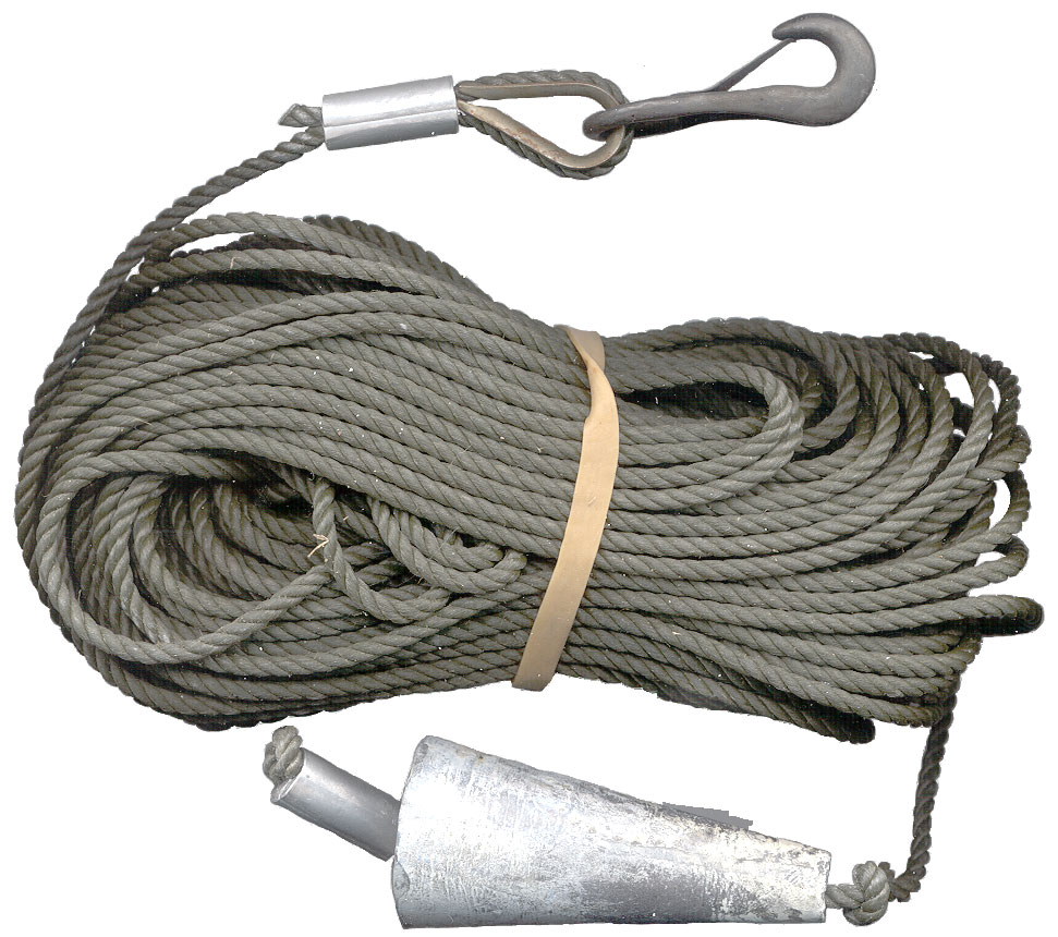
field use, not base station. It would be deployed by
throwing the weighted end of the halyard over a tree branch.
Since the halyard is 75 feet long the highest the antenna can be
is about 40 feet up. For operation at 1.8 MHz (160 meters)
the antenna should be up at least 1/4 wave length ( 40 meters or
about 120 feet) for good horizontal propagation. So for
frequencies below about 6 Mhz the antenna acts like a Near Vertical Incidence
Skywave (NVIS) antenna and sends most of it's energy
straight up. This provides good coverage out to a few
hundred miles. The manual mentioned that in a jungle
environment a 15 foot vertical antenna looses a lot of it's signal
to the trees and the GRA-50 will do much better.
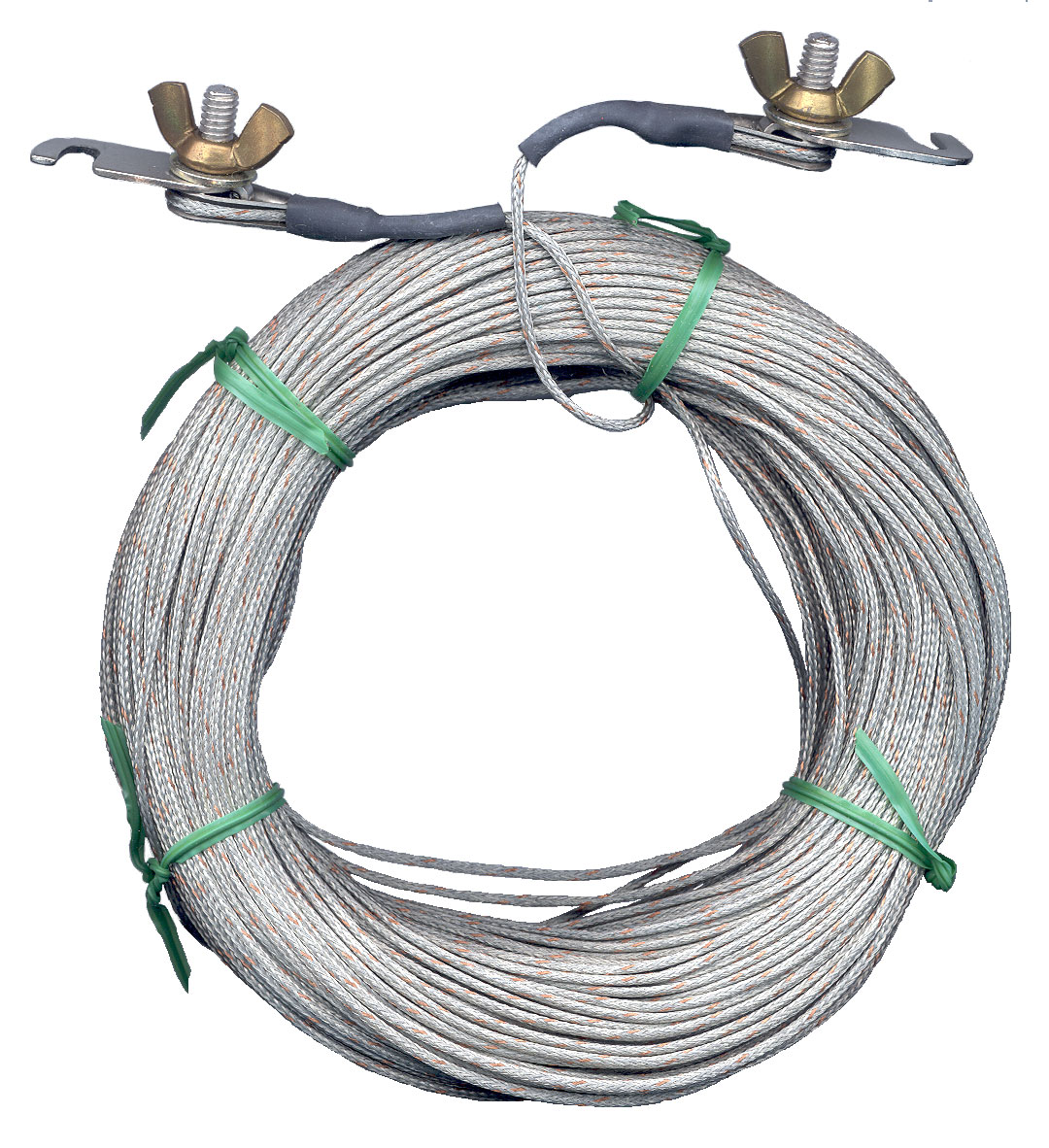
Construction
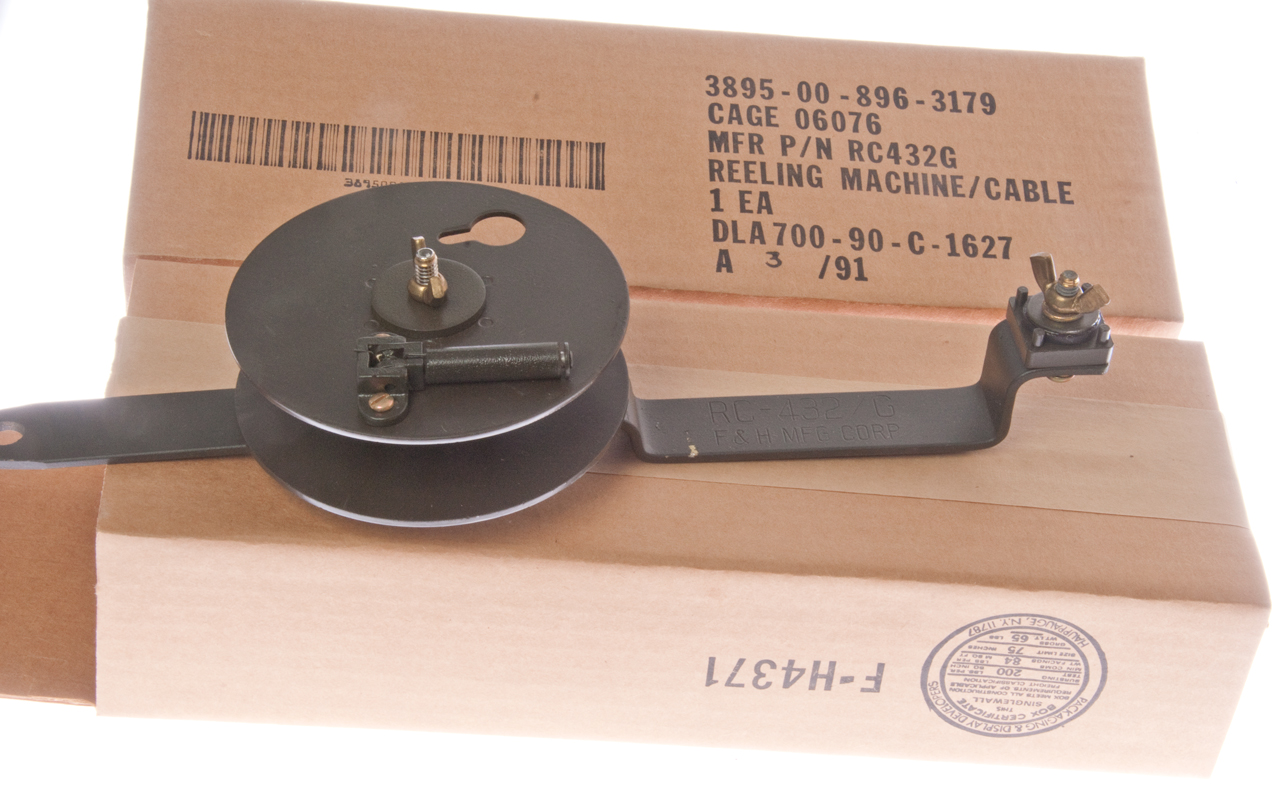
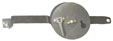
The two dipole elements are on reels so that the length
of the doublet can be adjusted to match the frequency of operation
anywhere in the 1.5 to 20 MHz range of the T-195
transmitter. But it could be used at higher frequencies.
Installing Wire on Reeling Machines
 A new
GRA-50 comes with the antenna wire separate from the Reeling
Machines. To install the wire:
A new
GRA-50 comes with the antenna wire separate from the Reeling
Machines. To install the wire:
In a location where you can work with 156 feet of wire tie off the
inner end of the wire and carefully remove one turn at a time as
you work your way to the other end. Attach the end to the
reel in such a way that when the wire is pulled it will tend to
tighten in the slot rather than come loose. Connect one end
of the wire to the reel by using a Wing Nut installed from inside
to the Large hole. The washer will fit on the wing nut side
of the hole.
Selecting Wire Length
The tape measure can be used or the formula Length of
each antenna wire in feet = 234 / (Freq in MHz)
This is equivalent to the overall dipole length in feet = 468 /
(Freq in MHz)
The amateur bands are harmonically related so if the antenna is
setup for 160 meters it should theoretically also will work on
40 and 10 meters but not 80 and 20 meters. i.e. it works
where each wire is an odd multiple of a quarter
wavelength. Because of ground proximity at the lower
frequencies it's not clear how the antenna impedance behaves
with frequency, something to actually measure. Stay tuned
(20 Oct 2002).
June 2006 - have a Tape Measure on the way.
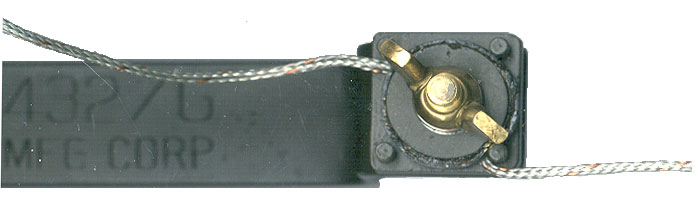
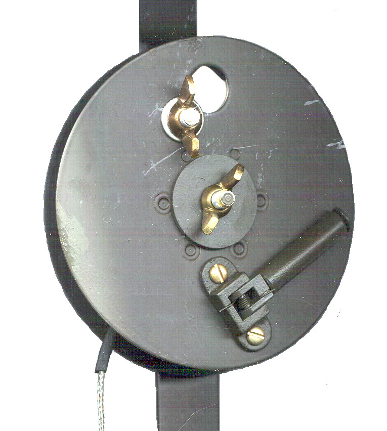
Using the Wire Clamp Wing Nut on the Reeling Machine
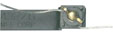 Under the Wire
Clamp there is a washer with a rubber washer below that. The
wire is installed between the metal frame of the Reeling Machine and
the rubber washer. It is routed over the first pin and under
the second pin so as to cause the wire to make two "U" turns that
hold the wire. The rubber is there to protect the wire NOT to
clamp it.
Under the Wire
Clamp there is a washer with a rubber washer below that. The
wire is installed between the metal frame of the Reeling Machine and
the rubber washer. It is routed over the first pin and under
the second pin so as to cause the wire to make two "U" turns that
hold the wire. The rubber is there to protect the wire NOT to
clamp it.
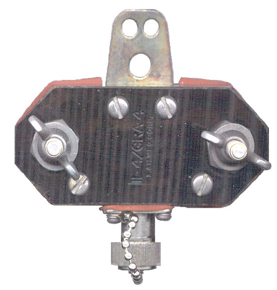
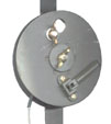
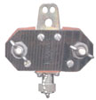
Center Insulator
The Center Insulator has holes to allow hanging it but
the standard GRA-50 kit does not include a Halyard for that
purpose.
With the type N connector pointing down and the wing nuts
visible the left wing nut is connected to the shield and the
right wing nut to the center conductor, if you want to make a
vertical antenna.
Parts List for GRA-50 FSN 5985-892-0758
|
Photo
|
Description
|
Nomenclature
|
Qty
|
FSN
|
|
|
Technical Manual |
|
1
|
TM 5820-467-15 |
|
Wanted
|
Bag |
BG-175 |
1
|
6115-498-3973 |
|
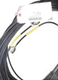
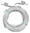
75' RG-58 Cable Assy
2 ea N(m) UG-536/U |
CG-678/U |
1
|
5995-823-2176 |
|
Center Insulator
with
N(m) connector & cap |
IL-4/GRA-4 |
1
|
5970-405-8223 |
|
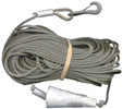
1/8" dia x 75' Halyard
with
8 oz lead weight |
MX-2706/G |
2
|
5985-893-1438
|

|
Cable Reeling Machine
2 new in box Jan 2015
|
RC-432/G |
2
|
5895-896-3179
3895-00-896-3179
p/n: RC-432G
CAGE: 06076
DLA700-90-C-1627
A 3/91
|
|
160' Antenna Wire |
CX-7303/G |
2
|
5985-757-2130 |
On it's way Jun
2006
|
Measuring Tape |
Arkay # 859-501 |
1
|
5210-897-6077 |
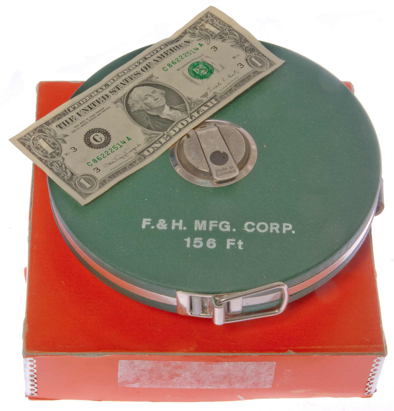
Tape Measure
Ordered one of these from Australia in 2006, but it never
arrived. The one I ordered was the Arkay No. 859-501.
In December 2014 I did get one with the same NSN 5210-897-6077
made by F. & H. Mfg. Corp., Germany.
It's larger than I expected at 7-3/8" diameter with a body
thickness of about a inch, much thicker the center over the
strap and crank.
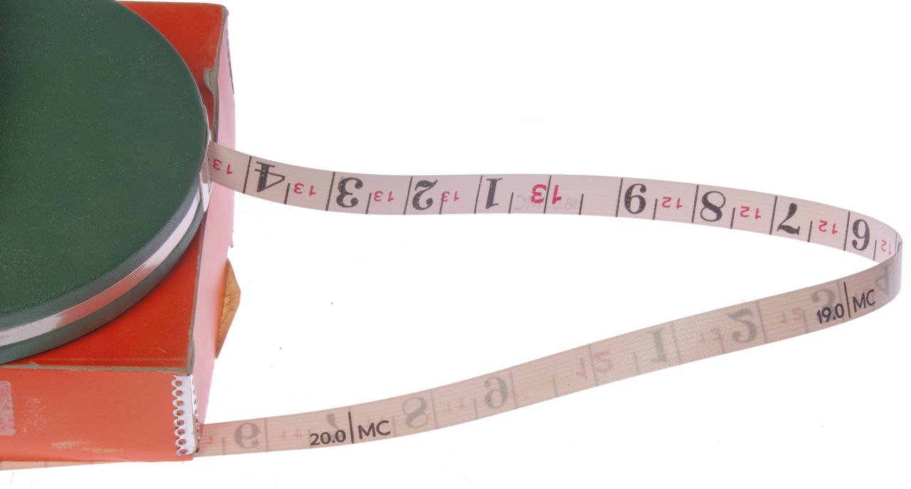
The front of the tape is marked in feet and tenths of a
foot. The back is marked in frequencies from 20.0 Mc to
1.5 Mc.
NOTE: the front is feet and tents of a foot, not feet and
inches. I may have misread the tape for some entries in
the table below.
NSN 5210-897-6077
Tape Radio Frequency
1 Each
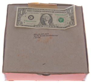
|
F. & H. Mfg. Corp. 156 Ft
Label has fallen off box.

|
20.0 Mc = 11.7', 19.0 Mc = 12.3'

|
Made in Germany

|
The tape is marked in the length of a 1/4 wavelength at the
frequency shown based on the formula:
1/4 Wavelength (ft) = 234' /(Freq Mc)
At 1.5 Mc a 1/4 wavelength is 156 feet and that's the maximum
length of the tape.
Note you need to measure two wires, each 1/4 wavelength
long, to make a dipole with the GRA-50 set.
Different columns for different frequency step sizes
1 MHz
|
|
0.5 MHz
|
0.2 MHz
|
|
0.1 MHz
|
|
0.05 MHz
|
|
0.02 MHz
|
|
|
Freq
Mc
|
Dist
Ft
|
20.0
|
11.7
|
19.0
|
12.3
|
18.0
|
13.0
|
17.0
|
13.8
|
16.0
|
14.7
|
15.0
|
15.7
|
14.0
|
16.8
|
13.0
|
18.0
|
12.0
|
19.6
|
11.0
|
21.3
|
|
|
Freq
Mc
|
Dist
Ft
|
11.0
|
21.3
|
10.5
|
22.3
|
10.0
|
23.5
|
9.5
|
24.7
|
9.0
|
26.0
|
8.5
|
27.6
|
8.0
|
29.3
|
7.5
|
31.3
|
7.0
|
33.5
|
|
Freq
Mc
|
Dist
Ft
|
7.0
|
33.5
|
6.8
|
34.5
|
6.6
|
35.5
|
6.4
|
36.6
|
6.2
|
37.8 |
6.0
|
39.0
|
5.8
|
40.4
|
5.6
|
41.8
|
5.4
|
43.4
|
5.2
|
45.0
|
5.0
|
46.0
|
4.8
|
48.8
|
4.6
|
50.9
|
4.4
|
53.2
|
4.2
|
55.8
|
4.0
|
58.6
|
|
|
Freq
Mc
|
Dist
Ft
|
4.0
|
58.6
|
3.9
|
60.0
|
3.8
|
61.6
|
3.7
|
63.3
|
3.6
|
65.0
|
3.5
|
66.9
|
3.4
|
68.9
|
3.3
|
70.0
|
3.2
|
73.2
|
3.1
|
75.5
|
3.0
|
78.0
|
|
|
Freq
Mc
|
Dist
Ft |
3.00
|
78.0
|
2.95
|
79.4
|
2.90
|
80.7
|
2.85
|
82.1
|
2.80
|
83.6
|
2.75
|
85.1
|
2.70
|
86.7
|
2.65
|
88.4
|
2.60
|
90.0
|
2.55
|
91.8
|
2.50
|
93.7
|
2.45
|
95.6
|
2.40
|
97.6
|
2.35
|
99.6
|
2.30
|
101.8
|
2.25
|
104.0
|
2.20
|
106.4
|
2.15
|
108.9
|
2.10
|
111.5
|
2.05
|
114.2
|
2.0
|
117.0
|
|
|
Freq
Mc |
Dist
Ft |
2.0
|
117.0
|
1.98
|
118.2
|
1.96
|
119.4
|
1.94
|
120.7
|
1.92
|
121.9
|
1.90
|
123.2
|
1.88
|
124.5
|
1.86
|
125.9
|
1.84
|
127.2
|
1.82
|
128.6
|
1.80
|
130.0
|
1.78
|
131.5
|
1.76
|
132.96
|
1.74
|
134.58
|
1.72
|
136.05
|
1.70
|
137.64
|
1.68
|
139.34
|
1.66
|
140.96
|
1.64
|
142.78
|
1.62
|
144.54
|
1.60
|
146.35
|
1.58
|
148.10
|
1.56
|
150.00
|
1.54
|
151.94
|
1.52
|
153.94
|
1.50
|
156.00
|
|
|
|
Manuals
TM 11-5820-467-15 Operator,
Organizational, Field, and Depot Maintenance Manual Antenna Group
AN/GRA-50
TM 11-5820-467-24P
Patents
3400402
Wire Antenna Extensible Along Calibrated Support Means, (Collins)
- GRA-50?
Links
Return to Brooke's Products for Sale,
Military Information, Antenna,
Electronics or Home
page
This is the [an error occurred while processing this directive] time
this page has been accessed since since 18 Oct. 2002.
 A new
GRA-50 comes with the antenna wire separate from the Reeling
Machines. To install the wire:
A new
GRA-50 comes with the antenna wire separate from the Reeling
Machines. To install the wire: