 |
 |
|
 |
 Home Brew HP 16138A Test Leads |
 |
Background
Yokogawa Hewlett Packard (YHP) made the 4332 LCR meter and continues to make a line of impedance measuring instruments to this day as Agilent Japan. This must be one of the earliest LCR meters in the HP line.
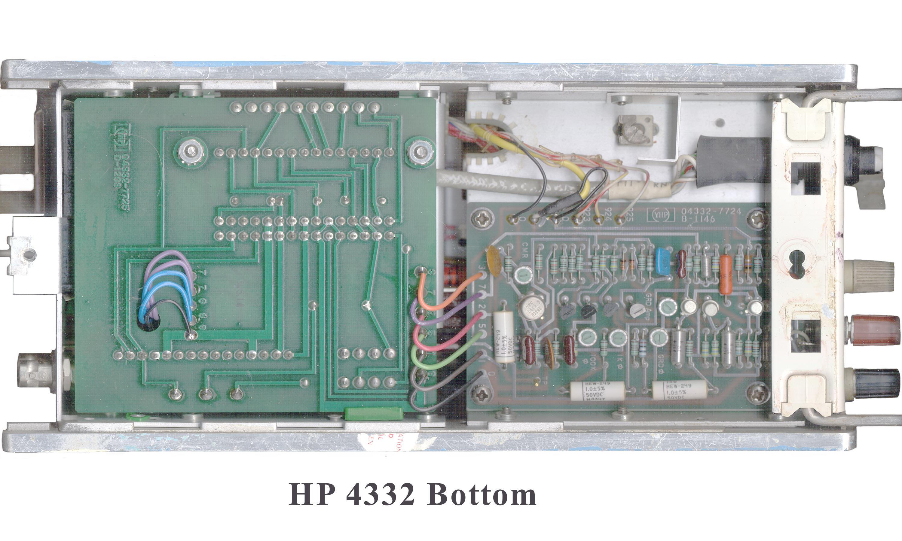
Description
The unknown device connects to the instrument by means of two 5-way binding posts. There is also a "Guard" binding post. This connection method is not as accurate as the newer methods for some impedance values but for the ranges covered here is fine. The guard terminal eliminates the lead capacitance when the HP 16138A test leads are used, or when an equivalent test lead is used.
On the low ranges the LC zero knob will zero the meter, but there is no zero for the R range. This is convenient since it allows zeroing for either L or C and then with a DUT connected you can switch to R thus it's easy to measure L&R or C&R.
Home Brew HP 16138A Test Leads
For the Hot and Guard I used a stock Dual Banana Plug to BNC(f) Jack adapter and a BNC(m) cable with the other end cut off. The outer cover and shield (guard) removed about 1/2" from the end and a small red grabber attached to the center conductor (Hot lead). A banana plug attached to a stranded black wire was used for the ground connection and tie wrapped to the coax up to about 3" from the grabber. A black grabber was attached to the black (common) lead.The current family of Agilent LCR meters uses a set of 4 BNC(f) connectors. Not all of the shields are at ground. There are a large number of test accessories for this configuration.
Example Measurements
L= 0.15 uH, R= 0.1 Ohm for a 5.5" long wire.
C=18.7 pF for a 19" length of twisted pair of hookup wire or about 1 pF per inch.
The junction capacitance of an LED changes from 39.5 pF with a bright light to 36.5 pF in the dark.
A ceramic cap marked .1 m measures 79 nF and 240 Ohms
A low loss cap marked .68 +/- 10% 100 DC measures 850 nF = .85 uF and 22 Ohms
A 10 uF Tantalum measures over range on the 1 uF scale 2.3 Ohms
A 0.015 uF Mylar cap measures 15.5 nF and 880 Ohms
A Silver Mica marked 2000 +/- 2% reads 1.98 nF and 800 Ohms
A silver Mica marked 22D reads 20.5 pF and > 1 M Ohm
A low loss cap marked .22 600V reads 210 nF and 74 Ohms
A 1 uF 50V Tantalum reads > 1 uF and 19 Ohms
A 470 uF electrolytic reads < 1uF and 0.35 Ohms
A 7 turn coil 1/$" dia reads 0.2 uH and 0.1 Ohm
A slug tuned coil reads 52 uH and 0.15 Ohms
A three leaded "E" laminated core inductor reads >1,000 mH and 300 k Ohms - has a lot of inductance
An inductor in a metal IF type can reads 0.2 uH and 0.1 Ohm
A ferrite bead on a wire reads 0.9 uH and 0.1 Ohm
A 1N4001 diode reads 25.5 pF and >1,000 K Ohms
A 2N3053 Transistor measures Ceb = 60 pF, Cbc = 16 pF and Cce = 16 pF
A 2N5109 reads Ceb = 12 pF, Cbc = 10.2 pF, C ec = 7.6 pF
A 2N2907 reads Ceb= 36 pF, Cbc = 22 pF and Cec = 17.4 pF
A 2N3904 reads Ceb =9.6 pF, C bc = 6.5 pF and C 6.0 pF
A Cadumum Sulfide photocell reads 200 Ohms & 15 nF & 25 uH dark and 40 Ohms & 150 nF & 2 uH in light
An LM340K-12 (TO-3 package) reads lead 1 to case 200 pF, lead 2 to case 12 pF lead 1 to 2 = 150 pF
A 7805K (TO-3 case) reads lead 1 to case 12 pF 4k2, lead 2 to case 270 pF 210k
The meter ranges are:
3 to 1,000 Ohms, pF or uH and 3 to 1,000 Ohms, nF or mH or 3 Ohms to 1 M Ohm, 3 pF to 1 uF and 3 uH to 1 H.
The first tick is 0.1 pF (100 fF), 0.1 Ohm (100 milli Ohm) or 0.1 uH (100 nH).
The test frequency is either 1 kHz or 100 kHz depending on the mode and range. The signal level is under 2 mV so it can be used to measure semiconductors without turning them on.
Resistance is always measured at 1 kHz and is a series value, like L in series with R or C in series with R.
A synchronous detector is used so that the real and imaginary parts are seperate. For example you can measure the inductance of an inductor in the "L" mode and then measure the resistance in the "R" mode on the same part.
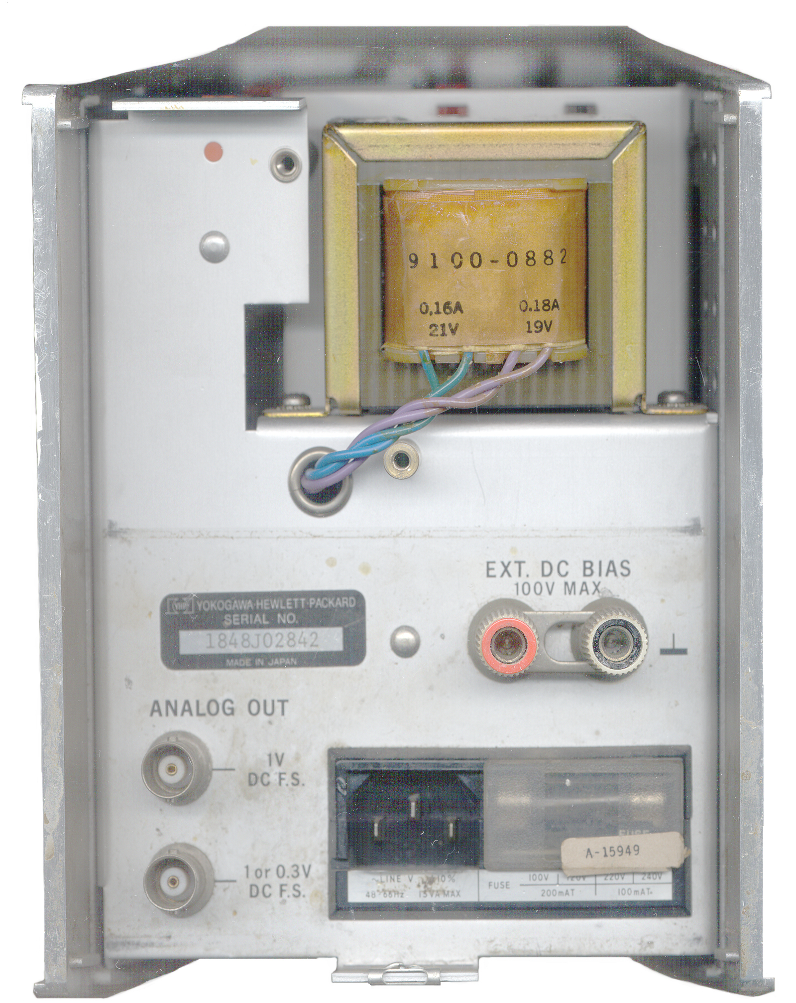
On the rear panel there are analog outputs of either 0 to 1 VDC for all ranges or on a different connector 1 or 0.3 V DC FS so that the output voltage corresponds to the measured value. There also is a pair of 5-way binding posts (Red and Black) that have a connecting link marked "Ext. DC Bias, 100 V Max.". with a ground symbol next to the black terminal which is connected to the instrument chassis. When the link is removed there is about 72 k Ohm between the rear Red terminal and the front panel HIGH terminal. It appears from this that you can only apply Dc bias to caps and only about 2 mA of current to inductors or resistors. It takes a modern IEC type line cord.
This particular instrument has seen a lot of use and needs the front panel knobs and 5-way binding posts replaced, but it is still working fine.
When microprocessors became available this instrument could have evolved into one of the later model LCR meters that measures both the real and imaginary part of the Device Under Test impedance and displays (L or C) and (R or D) at the same time.
Manual
The hard copy manual I have is 04332-99003 (04332-00053 is microfiche) for serial numbers 1703J-nnnnn but my LCR meter is has a serial number prefix of 1848J___ meaning that it was made in 1978 week 48 in Japan. The earliest model would have serial prefix 1146 J meaning they made this meter from 1971 to at least 1978 a run of 7 years.
Loop Antennas & Computer Monitors
When attempting to measure the inductance of Ferrite core loop antennas (Amidon R33-050-750 core with hundreds of turns of wire (2 to 10 mH inductance) the meter needle fluctuates a lot as the coil is moved into different orientations. The 4 layer bank wound coil pins the meter. The 2 layer bank wound coil reads about 1.5 mH but is very sensitive to handling on the hot lead. Moving the coil near the computer monitor pins the meter.
Related Instruments
Heathkit IB-5281LCR Impedance Bridge
HP 4260A ZM71A/U Universal Bridge
HP 4328A Milli Ohm meter in same size box
Marconi TF-2700 1 kHz Universal LCR Bridge
Omega-T TE7 Antenna Noise Bridge
ZM-4 DC bridge
ZM-11 AC LCR Bridge
HP/Agilent 4395A Impedance Analyzer
CD-ROM Manual
I have scanned, cleaned, and linked the manual and it's available on CD-ROM. The large versions of all the above color photos are also on the manual as part of the manual pdf file. The previous manual owner was a cal lab and I have left their yellow highlights and markings since they add value.
This manual is NOT on my CDWM.
See the Products page for ordering info
Back to Brooke's Products for Sale, Test Equipment, Microwave Test equipment, Military Information, Home page
This is the [an error occurred while processing this directive] time
this page has been accessed since since 25 April 2003.