Leclanché Battery
Short History of the Flashlight Battery
© Brooke Clarke 2005 - 2026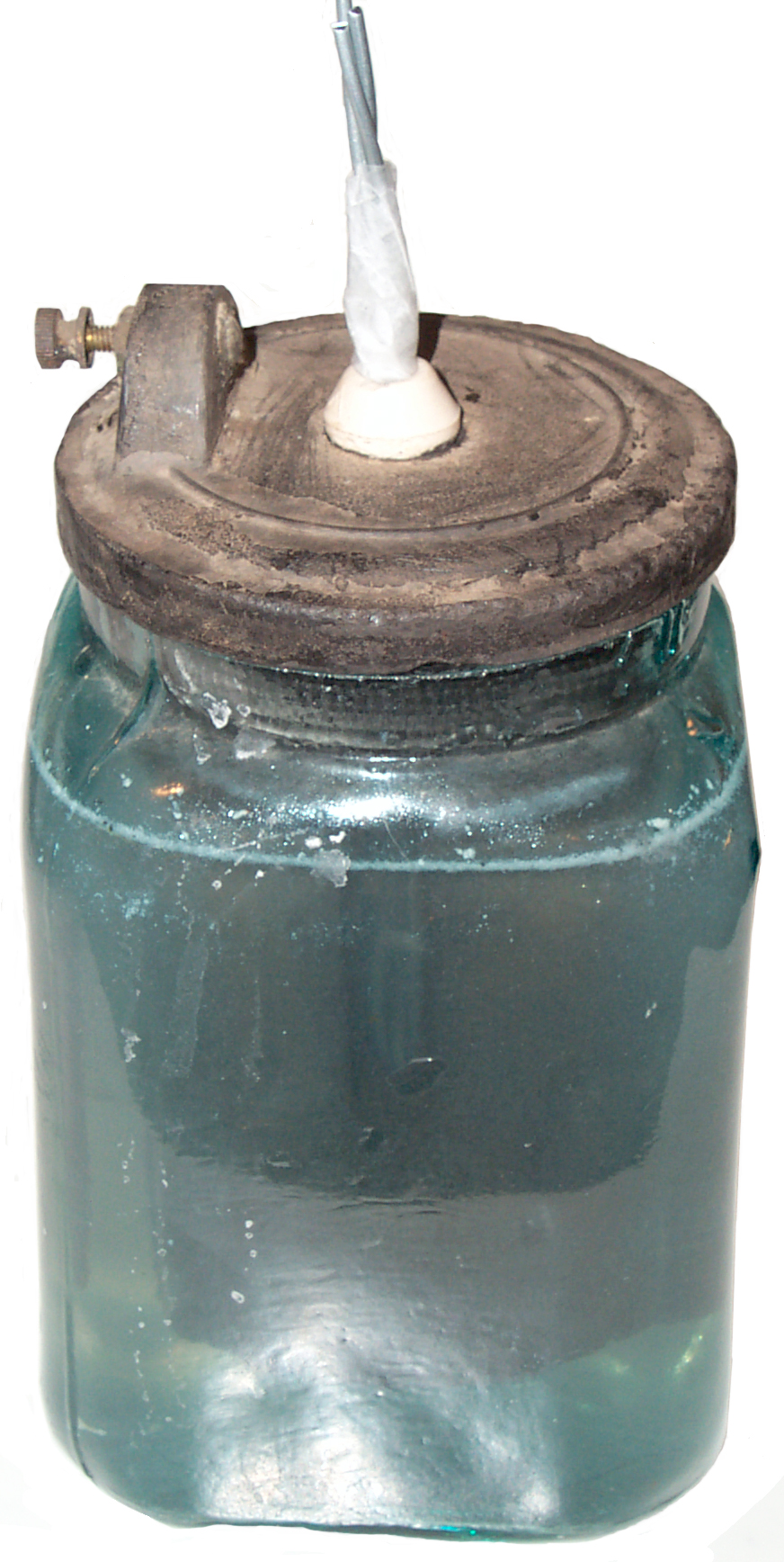 |
 |
| Working 100 to 131 Year old
Battery The neat thing is that it's sustainable and renewable technology 1 liter liquid |
New Battery 500 ml liquid |
Background
Battery Time Line
My Batteries
Instructions on glass jar
Gravity (Crow's foot) Battery (pre dated Leclanché)
Fuller Cell
Patents
Battery Patent
Flashlight
Telegraph Sounder
Links
Telegraph Equipment - seperate web page
Telephones - seperate web page
Telephone patents - seperate web page
The sulfuric acid in lead acid batteries is much more a
problem that
the milder electrolytes used in all the above batteries.
So they
were not used for telegraph and/or telephone circuits.
 12 Dec 2006 - I got a couple of Peerless wet batteries on
eBay.
They do not use a porous cup for the manganese dioxide and
instead have
it combined with the carbon like in the Leclanché
patent 165452 . The Zinc rod was missing and goes
through a hole in the center of the carbon block. A
white
porcelain insulator, like was used in early electrical wiring,
is used
to keep the Zinc rod from shorting to the carbon block.
12 Dec 2006 - I got a couple of Peerless wet batteries on
eBay.
They do not use a porous cup for the manganese dioxide and
instead have
it combined with the carbon like in the Leclanché
patent 165452 . The Zinc rod was missing and goes
through a hole in the center of the carbon block. A
white
porcelain insulator, like was used in early electrical wiring,
is used
to keep the Zinc rod from shorting to the carbon block.
The glass jar is about 110 mm square and 160mm tall. The complete battery with electrolyte weighs about 5.5 pounds.
A local electrician is on the lookout for a couple of the porcelain insulators to replace the missing one and the broken one.
I've added to the photo a catalog drawing of the "Pencil Zinc" that was meant to be used but have some Zinc wire and rod stock on order.
There are two slots in the carbon block that allow you to see the Zinc rod in the center. Maybe this is so you can see when the Zinc rod has been consumed and needs to be replaced? Also there is a 3/8 to 3/4" gap between the bottom of the carbon block and the bottom of the glass jar, maybe to allow some zinc compound to settle to the bottom without effecting battery operation.
Note that the top cap overlaps the top of the jar. The top surface of the jar has been ground on a flat surface so it mates to the bottom of the cap in an almost air tight way. By applying a small amount of "battery oil" to the joint between the jar and cap it becomes an air tight seal. I may also be the case that the insulator and zinc rod are a close fit and can also be sealed using a small amount of "battery oil". The air tight seal prevents the water from evaporating allowing the battery to work until the zinc is consumed.
A battery looking just like the one above on eBay has a paper label saying:
The Peerless batteries may by circa 1905, well after the Leclanché patent 165452.
14 Dec. 2006 - 1 liter of water and 6 level tablespoons of Ammonium Chloride mixed well and micro waved a little to warm it up.
Open Circuit Voltage about 1 and rising and short circuit current of about 500 ma.
Instead of a 1.4" dia. Zinc rod I'm using a piece of 0.091" dia Zinc wire. It has a problem in that it can tilt and touch the carbon/magnesium dioxide block. A rod would be better centered. The 3/8" zinc rod is too large to fit inside the white porcelain insulator.
Roto Metals has Zinc rods and wire
There are a number of sellers on eBay tha have Ammonium Chloride
Using 3 Zinc wires and warping the top part with scotch tape to make the diameter fit the porcelain insulator the wires stay centered.
OCV is not about 1.2 volts and SCC is about 600 ma.
Note that this battery is over 100 years old. It's made from an 1875 patent.
Note1 - After sitting overnight the water is now
clear, not
the foggy appearance when first mixed. There are crystals
of
Ammonium Chloride on the bottom of the jar. So maybe 6
level
tablespoons was a little too much Ammonium Chloride, but it's
good to
have a saturated solution.
Note2 - After leaving the 11 Ohm load on for many hours the voltage across the load is stable at 0.75. But the No. 6 battery is specified to power this load for 380 hours and is at >= 0.9 Volts at the end of that time. The current would start at 1.5/10 = 150 ma and end at 0.9/10 = 90 ma, but my wet cell is only delivering about 75 ma. So if the No. 6 battery replaced the wet cell then the output should be about the same. But so far I have not found any specifications for wet cell batteries.
It may help to use sandpaper to clean the surface of the carbon block or maybe use water that has had the oxygen boiled out. Or maybe this is the performance of the battery when it was new?
This is twice as concentrated as what I used for the old battery (1 liter & 6 level tbl spoons). After adding the NH4Cl and the Zinc rod the liquid level is at the bottom of the black band around the top of the porous cup.
This new battery is missing the air tight seal to prevent evaporation. That's consistent with the idea it was made for a school class demonstration rather for use in a working environment.
Just after activating the new battery it had an Open Circuit Voltage of 1.688 V and a Short Circuit Current of 200 ma. The new battery will dimly light an LED but the old battery will not.
After a day or two will try swapping various parts to see which is the key factor.
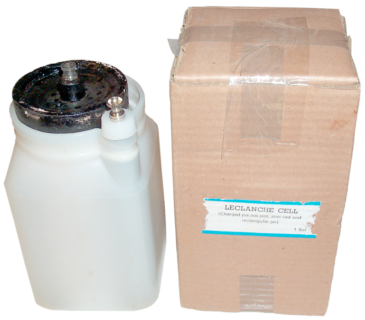
Note that the new battery comes with a white plastic jar that has a place for the Zinc rod in one corner. And a pre-assembled porus cup that's 1 7/8" diameter (similar to a No. 6 dry battery).
If you know where the new batteries are made let me know.
 2
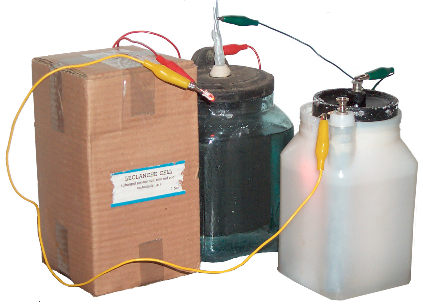
Jan 2007 - Connecting the old and new batteries in series with
an LED
and 27 Ohm resistor lights the LED. Since the capacity of
a No. 6
dry cell Leclanché
Battery is about 52 Amp Hours I expect this setup would light
the LED
for about 4.5 months. The current is about 16 ma and the
LED
voltage is about 2 Volts.
2
Jan 2007 - Connecting the old and new batteries in series with
an LED
and 27 Ohm resistor lights the LED. Since the capacity of
a No. 6
dry cell Leclanché
Battery is about 52 Amp Hours I expect this setup would light
the LED
for about 4.5 months. The current is about 16 ma and the
LED
voltage is about 2 Volts.
9 Jan 2007 - LED has been on 24/7.
15 Jan 2007 - When walking near the batteries the LED flickers. It's because the zinc wires I put in the old battery are getting eaten up and only a small area remains below the electrolyte. I expect the LED to turn off shortly when all the zinc has been consumed.
18 Jan 2007 - the LED is on but very weak, I think the zinc must be almost gone.
 21 Jan 2007 -
the LED has turned off.
21 Jan 2007 -
the LED has turned off.
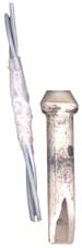
The starting zinc was 3 wires each 0.091" dia by 9 inches long.
Now there are 3 wires each 4.25" long. The relative position of the wires and insulator in the photo is slightly off. The bottom end of the wires are about 1 inch up from the bottom of the insulator. Capillary action has pulled the electrolyte up into the insulator and that column of liquid has eaten the bottom end of the wires. So 3 wires 4.75" long have been consumed by 17 ma for 19 days.
The zinc rod in the new battery, although black, looks about the same as when new. I don't know if the new zinc has been amalgated with a mercury coating or if the small amount of use is because of it's larger 0.478" diameter.
The new zinc rod for the old battery is 8.1" long x 0.37' dia. scotch tape used to make an insulator to keep it from touching the carbon block. Installed 21 Jan 2007 13:20. It's resting on the bottom of the glass jar. Not good since as it's used up it will fall down. Should be suspended from the top.
4 April 2007 - 75 % of the water in the modern cell has evaporated (there's a 1/2" gap outside the porous pot and the jar's top lip. But the old glass cell has 100% of it's water (the carbon block sits on top of the lip like a lid & there's only a 1/8" gap between the Zinc rod and the hole in the carbon block). Although a little dimmer than at the start the LED was still glowing and was on a 24/7 basis until today when my wife ran into the stack holding these and spilled some electrolyte when the new cell fell to the floor. stop test
Battery Time Line
My Batteries
Instructions on glass jar
Gravity (Crow's foot) Battery (pre dated Leclanché)
Fuller Cell
Patents
Battery Patent
Flashlight
Telegraph Sounder
Links
Telegraph Equipment - seperate web page
Telephones - seperate web page
Telephone patents - seperate web page
Background
The Voltaic cell was invented
about
1800 and consisted of two dissimilar metals immersed in an
acid
solution. The same chemistry as a lemon battery using a
galvanized nail and copper penny. This cell has a very
feeble
output and uses acid that's not human friendly. When the
telegraph system was the primary means of communication in the
1830 to
1880 time frame
batteries
were needed at every telegraph station. The Leclanché
Battery offered a more powerful battery and at the same time a
more
user friendly battery. Although it uses a primary
chemistry it
could be charged by replacing the electrolyte for a small
cost.
So millions of them were made.
Later when the telephone required a local battery these same cells were used until they were replaced with a different physical form of the same chemistry called the No. 6. The No. 6 was a "dry cell" and was more convenient than the Leclanché wet cell. When the dry cell goes dead it can not be reused and is thrown in the trash.
A primary battery is one where the chemistry only works one way. You can not put electricity back into a primary battery to recharge it. A secondary battery is one where the chemistry works both ways and so it can be recharged using electricity.
The Leclanché Battery is a primary chemistry type, but was made in an open glass jar (called a wet cell) so that when the battery was dead the electrolyte could be dumped out and fresh electrolyte put back in thus chemically recharging the battery.
Georges Lionel Leclanché (1839-1882) pioneered a battery that did not use acid but instead used Sal Ammoniac (ammonium chloride) electrolyte along with a metallic zinc rod anode and a carbon and natural manganese dioxide cathode. He is the father of the modern AA, C, D and 9 volt batteries that are so common today.
Eveready in the UK was making wet cell batteries of this design into the 1957 time frame.
Woodhouse & Rawson was also making them up until ___?___ and they were sued by Edison and the court ruled that his electric light patent was valid. They went out of business shortly thereafter (189?).
In their 1960 battery handbook Eveready had a few pages about Leclanché cells. Not wet cells but the same chemistry in flashlight battery form. It mentions that there's a tradeoff in how much carbon is mixed with the MnO2. More carbon gives higher currents but lower capacity. Photoflash batteries use more carbon so that they can supply higher peak currents, but flashlight batteries use more MnO2 so that they last longer.
Note that the Zinc rod may corrode and to prevent that it can be amalgamated with Mercury. This was done in Zinc-Carbon (Leclanché) flashlight batteries and later in Alkaline flashlight batteries. But when Mercury was removed from all batteries for environmental reasons there was a need for a complete redesign of Alkaline batteries. Many of the patent numbers you see on batteries relate to how this was done.
Materials can be listed in what's called Galvanic order. See the Galvanic Table at On Line Metals for an example. When designing a machine it's bad practice to place two metals together that have a big separation in the table. Doing so leads to corrosion and/or electrical offsets. But for making a battery it's good to do. Notice that Graphite is third from the top of the list and that Zinc is third from the bottom of the list.
Later when the telephone required a local battery these same cells were used until they were replaced with a different physical form of the same chemistry called the No. 6. The No. 6 was a "dry cell" and was more convenient than the Leclanché wet cell. When the dry cell goes dead it can not be reused and is thrown in the trash.
A primary battery is one where the chemistry only works one way. You can not put electricity back into a primary battery to recharge it. A secondary battery is one where the chemistry works both ways and so it can be recharged using electricity.
The Leclanché Battery is a primary chemistry type, but was made in an open glass jar (called a wet cell) so that when the battery was dead the electrolyte could be dumped out and fresh electrolyte put back in thus chemically recharging the battery.
Georges Lionel Leclanché (1839-1882) pioneered a battery that did not use acid but instead used Sal Ammoniac (ammonium chloride) electrolyte along with a metallic zinc rod anode and a carbon and natural manganese dioxide cathode. He is the father of the modern AA, C, D and 9 volt batteries that are so common today.
Eveready in the UK was making wet cell batteries of this design into the 1957 time frame.
Woodhouse & Rawson was also making them up until ___?___ and they were sued by Edison and the court ruled that his electric light patent was valid. They went out of business shortly thereafter (189?).
In their 1960 battery handbook Eveready had a few pages about Leclanché cells. Not wet cells but the same chemistry in flashlight battery form. It mentions that there's a tradeoff in how much carbon is mixed with the MnO2. More carbon gives higher currents but lower capacity. Photoflash batteries use more carbon so that they can supply higher peak currents, but flashlight batteries use more MnO2 so that they last longer.
Note that the Zinc rod may corrode and to prevent that it can be amalgamated with Mercury. This was done in Zinc-Carbon (Leclanché) flashlight batteries and later in Alkaline flashlight batteries. But when Mercury was removed from all batteries for environmental reasons there was a need for a complete redesign of Alkaline batteries. Many of the patent numbers you see on batteries relate to how this was done.
Materials can be listed in what's called Galvanic order. See the Galvanic Table at On Line Metals for an example. When designing a machine it's bad practice to place two metals together that have a big separation in the table. Doing so leads to corrosion and/or electrical offsets. But for making a battery it's good to do. Notice that Graphite is third from the top of the list and that Zinc is third from the bottom of the list.
Battery Time Line
| Year |
Name |
Comment |
| 1800 |
Volta |
Pile of copper &
zinc seperated by electrolyte |
| 1821 |
Seebeck | called a thermopile (based on the
"pile" name by Volta used by Simon Ohm 1825 to develop Ohms law |
| 1836 |
Daniell |
porous cup seperates
copper and zinc |
| 1859 |
Planté | Lead Acid cell |
| 1860 |
Callaud |
Gravity cell eliminates
the porous cup from Daniell cell |
| 1866
-1880 |
Leclanché | Zinc & carbon
porous cup and later without cup |
| 1887 |
Gassner | Zinc carbon dry battery |
My Batteries
On order are a couple of NEW wet cell batteries. These are intended for use in chemistry/physics classrooms. We'll see if they have any specifications and how they compart to the 100+ year batteries. 12 Dec 2006 - I got a couple of Peerless wet batteries on
eBay.
They do not use a porous cup for the manganese dioxide and
instead have
it combined with the carbon like in the Leclanché
patent 165452 . The Zinc rod was missing and goes
through a hole in the center of the carbon block. A
white
porcelain insulator, like was used in early electrical wiring,
is used
to keep the Zinc rod from shorting to the carbon block.
12 Dec 2006 - I got a couple of Peerless wet batteries on
eBay.
They do not use a porous cup for the manganese dioxide and
instead have
it combined with the carbon like in the Leclanché
patent 165452 . The Zinc rod was missing and goes
through a hole in the center of the carbon block. A
white
porcelain insulator, like was used in early electrical wiring,
is used
to keep the Zinc rod from shorting to the carbon block.The glass jar is about 110 mm square and 160mm tall. The complete battery with electrolyte weighs about 5.5 pounds.
A local electrician is on the lookout for a couple of the porcelain insulators to replace the missing one and the broken one.
I've added to the photo a catalog drawing of the "Pencil Zinc" that was meant to be used but have some Zinc wire and rod stock on order.
There are two slots in the carbon block that allow you to see the Zinc rod in the center. Maybe this is so you can see when the Zinc rod has been consumed and needs to be replaced? Also there is a 3/8 to 3/4" gap between the bottom of the carbon block and the bottom of the glass jar, maybe to allow some zinc compound to settle to the bottom without effecting battery operation.
Note that the top cap overlaps the top of the jar. The top surface of the jar has been ground on a flat surface so it mates to the bottom of the cap in an almost air tight way. By applying a small amount of "battery oil" to the joint between the jar and cap it becomes an air tight seal. I may also be the case that the insulator and zinc rod are a close fit and can also be sealed using a small amount of "battery oil". The air tight seal prevents the water from evaporating allowing the battery to work until the zinc is consumed.
A battery looking just like the one above on eBay has a paper label saying:
DIRECTIONS
FOR CLEANING CARBON CYLINDER BATTERIES.
FOR CLEANING CARBON CYLINDER BATTERIES.
Remove
the carbon cylinder and hold it
in a gas flame for a few moments, turning it
to apply the flame to all parts. Scrape off
the white matter that will appear on the sur-
face. Wet the carbon and repeat the oper-
ation two to three times till no white matter
appears and the carbon becomes coated with
soot from the gas flame.
Dissolve a charge of sal ammoniac un the
solution in the jar, replace the carbon and
the battery will be ready for immediate use.
in a gas flame for a few moments, turning it
to apply the flame to all parts. Scrape off
the white matter that will appear on the sur-
face. Wet the carbon and repeat the oper-
ation two to three times till no white matter
appears and the carbon becomes coated with
soot from the gas flame.
Dissolve a charge of sal ammoniac un the
solution in the jar, replace the carbon and
the battery will be ready for immediate use.
The Peerless batteries may by circa 1905, well after the Leclanché patent 165452.
14 Dec. 2006 - 1 liter of water and 6 level tablespoons of Ammonium Chloride mixed well and micro waved a little to warm it up.
Open Circuit Voltage about 1 and rising and short circuit current of about 500 ma.
Instead of a 1.4" dia. Zinc rod I'm using a piece of 0.091" dia Zinc wire. It has a problem in that it can tilt and touch the carbon/magnesium dioxide block. A rod would be better centered. The 3/8" zinc rod is too large to fit inside the white porcelain insulator.
Roto Metals has Zinc rods and wire
There are a number of sellers on eBay tha have Ammonium Chloride
Using 3 Zinc wires and warping the top part with scotch tape to make the diameter fit the porcelain insulator the wires stay centered.
OCV is not about 1.2 volts and SCC is about 600 ma.
When I measured the current I
didn't think is was real, but I now do. This came about
after working with the Toy Motor Kit
that was designed to be powered by a single No. 6 Dry
Cell. The
motor will attempt to draw 17 amps from the 1.5 volt No. 6 Dry
Cell. I expect that the 600 ma was the current limit
caused by
the test leads and internal resistance of the Fluke 87 Digital
Multimeter used to make the measurement and that a much higher
current
would be produced by a lower resistance circuit.
Note that this battery is over 100 years old. It's made from an 1875 patent.
| Date |
Time |
OCV V |
SCC ma |
100 Ohms |
| 14 Dec 06 |
16:00 |
1.26 |
900 |
|
| 14 Dec 06 | 20:00 |
1.374 |
900->800->700 |
1.145 v |
| 15 Dec 061 |
10:45 |
1.40 |
700 |
1.25 |
| 15 Dec 062 |
14:00 |
.75v @ 11 Ohms |
||
| 15 Dec 06 |
17:30 |
.74v @ 11 Ohms |
||
| 16 Dec 06 |
10:30 |
.74v @ 11 Ohms |
Note2 - After leaving the 11 Ohm load on for many hours the voltage across the load is stable at 0.75. But the No. 6 battery is specified to power this load for 380 hours and is at >= 0.9 Volts at the end of that time. The current would start at 1.5/10 = 150 ma and end at 0.9/10 = 90 ma, but my wet cell is only delivering about 75 ma. So if the No. 6 battery replaced the wet cell then the output should be about the same. But so far I have not found any specifications for wet cell batteries.
It may help to use sandpaper to clean the surface of the carbon block or maybe use water that has had the oxygen boiled out. Or maybe this is the performance of the battery when it was new?
New Battery
1 Dec 2006 - Activated one of the new batteries. Uses 500 ml of distilled water and 7 level tablespoons of NH4Cl. I'm just guessing on the NH4Cl. This is half the volume of the older battery.This is twice as concentrated as what I used for the old battery (1 liter & 6 level tbl spoons). After adding the NH4Cl and the Zinc rod the liquid level is at the bottom of the black band around the top of the porous cup.
This new battery is missing the air tight seal to prevent evaporation. That's consistent with the idea it was made for a school class demonstration rather for use in a working environment.
Just after activating the new battery it had an Open Circuit Voltage of 1.688 V and a Short Circuit Current of 200 ma. The new battery will dimly light an LED but the old battery will not.
After a day or two will try swapping various parts to see which is the key factor.
Note that the new battery comes with a white plastic jar that has a place for the Zinc rod in one corner. And a pre-assembled porus cup that's 1 7/8" diameter (similar to a No. 6 dry battery).
If you know where the new batteries are made let me know.
 2
Jan 2007 - Connecting the old and new batteries in series with
an LED
and 27 Ohm resistor lights the LED. Since the capacity of
a No. 6
dry cell Leclanché
Battery is about 52 Amp Hours I expect this setup would light
the LED
for about 4.5 months. The current is about 16 ma and the
LED
voltage is about 2 Volts.
2
Jan 2007 - Connecting the old and new batteries in series with
an LED
and 27 Ohm resistor lights the LED. Since the capacity of
a No. 6
dry cell Leclanché
Battery is about 52 Amp Hours I expect this setup would light
the LED
for about 4.5 months. The current is about 16 ma and the
LED
voltage is about 2 Volts.9 Jan 2007 - LED has been on 24/7.
15 Jan 2007 - When walking near the batteries the LED flickers. It's because the zinc wires I put in the old battery are getting eaten up and only a small area remains below the electrolyte. I expect the LED to turn off shortly when all the zinc has been consumed.
18 Jan 2007 - the LED is on but very weak, I think the zinc must be almost gone.
 21 Jan 2007 -
the LED has turned off.
21 Jan 2007 -
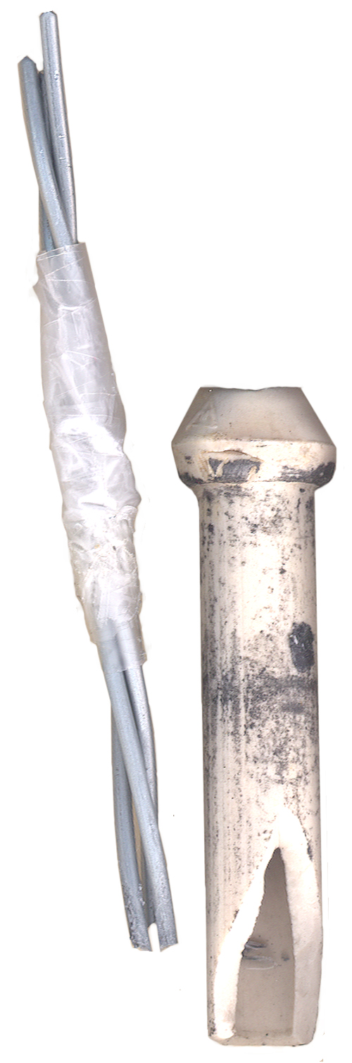
the LED has turned off.The starting zinc was 3 wires each 0.091" dia by 9 inches long.
Now there are 3 wires each 4.25" long. The relative position of the wires and insulator in the photo is slightly off. The bottom end of the wires are about 1 inch up from the bottom of the insulator. Capillary action has pulled the electrolyte up into the insulator and that column of liquid has eaten the bottom end of the wires. So 3 wires 4.75" long have been consumed by 17 ma for 19 days.
The zinc rod in the new battery, although black, looks about the same as when new. I don't know if the new zinc has been amalgated with a mercury coating or if the small amount of use is because of it's larger 0.478" diameter.
The new zinc rod for the old battery is 8.1" long x 0.37' dia. scotch tape used to make an insulator to keep it from touching the carbon block. Installed 21 Jan 2007 13:20. It's resting on the bottom of the glass jar. Not good since as it's used up it will fall down. Should be suspended from the top.
4 April 2007 - 75 % of the water in the modern cell has evaporated (there's a 1/2" gap outside the porous pot and the jar's top lip. But the old glass cell has 100% of it's water (the carbon block sits on top of the lip like a lid & there's only a 1/8" gap between the Zinc rod and the hole in the carbon block). Although a little dimmer than at the start the LED was still glowing and was on a 24/7 basis until today when my wife ran into the stack holding these and spilled some electrolyte when the new cell fell to the floor. stop test
Instructions on glass jar
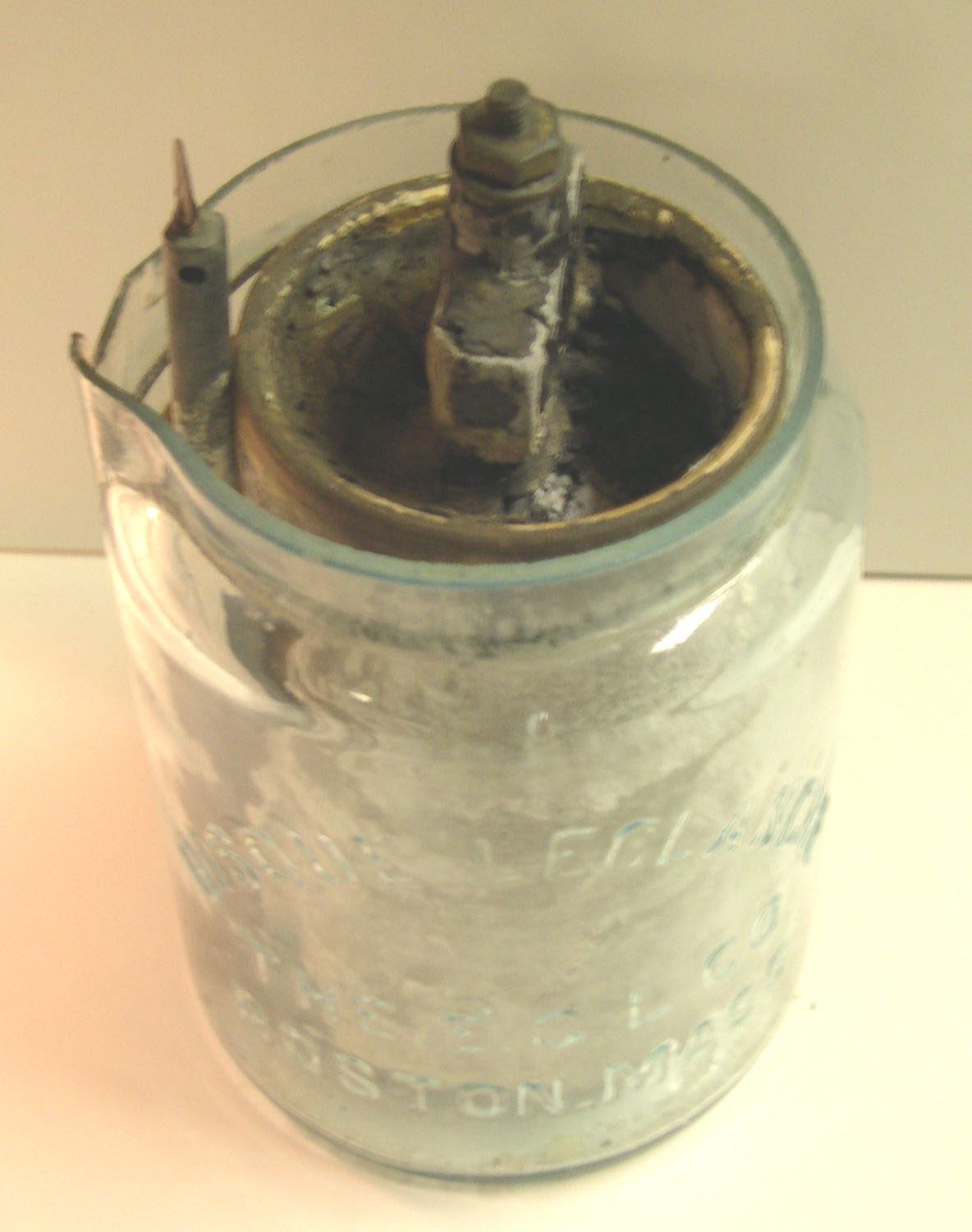 Photo and
instructions from Fred Coady.
Photo and
instructions from Fred Coady.
“OUR OWN” DISQUE LECLANCHE BATTERY
DIRECTIONS FOR SETTING UP AND USING
First – Put the contents of paper bag (Sal Ammoniac) in the glass jar, fill one third full of warm water, and stir well.
Second – Insert the Porous Cup and Zinc, being careful that the mixture does not rise within 1 1\2 inches of the top, or quite up to the line of paraffine.
Third – Pour a little water into the air holes of Porous Cups and let the cells stand a few hours before connecting the poles, so that the solution may saturate the contents of the Cups.
Note – If immediate work is required, use HOT WATER.
The battery should not be set to work, however, until the Porous Cup and its contents are well soaked.
Fourth – Set the Battery in a dry, cool place. See that the connections are clean and firmly made, and that the connecting wires are properly insulated.
Fifth – When adding water or Sal Ammoniac to supply the loss by evaporation, be careful to keep the top of the Porous Cup and Jar entirely dry and clean.
Sixth – When the Battery fails to work satisfactorily, throw out the solution and substitute a fresh charge of Sal Ammoniac and Water
THE ELECTRIC GAS LIGHTING CO.
195 Devonshire Street, - 56 Arch Street
BOSTON, MASS.
Note: Since this was not made by the Leclanché Battery Co. of N.Y. it probably was made after the Leclanché Patents had run out.
Gravity Battery (Daniell cell)
The Daniell cell
(1.1 volts per cell) was patented in 1836
by John Daniell. In the 1860's Callaud patented the
Gravity Cell
which eliminated the need for a porous cup.
The Gravity battery consists of a clear glass cylindrical jar with a Copper "crow's foot" at the bottom and a Zinc "crow's foot" st the top.
Copper Sulphate liquid (blue vitriol, bluestone) settles to the bottom and Zinc Sulphate floats on top of it.
Floating Battery Oil (pure Mineral Oil) on top prevents evaporation.
See patent 39571 below.
http://www.n7cfo.com/Tgph/wu/a-c.htm
http://www.chss.montclair.edu/~pererat/mbatt.htm
The Gravity battery consists of a clear glass cylindrical jar with a Copper "crow's foot" at the bottom and a Zinc "crow's foot" st the top.
Copper Sulphate liquid (blue vitriol, bluestone) settles to the bottom and Zinc Sulphate floats on top of it.
Floating Battery Oil (pure Mineral Oil) on top prevents evaporation.
See patent 39571 below.
http://www.n7cfo.com/Tgph/wu/a-c.htm
http://www.chss.montclair.edu/~pererat/mbatt.htm
Fuller Cell
This may be an
early Leclanché type cell, but before any of the Leclanché
patents, so has a different name.
Patents
Flashlight Patents
Telegraph Sounder Patents
4 Ohm sounders
are for local loops
(under say 100 feet). 20 Ohm sounders are for up to 15
mile
lines. Higher Ohm sounders are for very long lines.
In most cases a relay is used on a long line and then 4 Ohm sounders can be used in the local loop. Battery was typically supplied at each end of a line by either Gravity and later Leclanché cells. The number of cells goes up like one cell per mile of line and per sounder.
In most cases a relay is used on a long line and then 4 Ohm sounders can be used in the local loop. Battery was typically supplied at each end of a line by either Gravity and later Leclanché cells. The number of cells goes up like one cell per mile of line and per sounder.
538816
Telegraphic Sounder J. H. Bunnell, May 7, 1895 178/100
- more sound from weak armature strikes than prior
sounders.
There are 38 newer sounder patents and 31 older sounder patents.
159894 Telegraph-Sounder 178/100 J. H. Bunnell, Feb. 16, 1875 -
Much more on the Telegraph web page
159894 Telegraph-Sounder 178/100 J. H. Bunnell, Feb. 16, 1875 -
Much more on the Telegraph web page
Links
YouTube: Big Clive.com: Reactivating
an 1800's Victorian Leclanché cell, 10:19 - only good for
a burst of high current, hence the name "Flash Light".
History of the Battery by Energizer, formerly Eveready formerly National Carbon Company
History of the battery @ Wikipedia
History of the Flashlights by Energizer
Pioneers of Electricity Georges Leclanché -
Early Batteries: The Voltaic Cell, The 'Gravity' or Crow's FootT Battery and other Telegraph Batteries
Flashlight Museum -
History of the Battery by Energizer, formerly Eveready formerly National Carbon Company
History of the battery @ Wikipedia
History of the Flashlights by Energizer
Pioneers of Electricity Georges Leclanché -
Early Batteries: The Voltaic Cell, The 'Gravity' or Crow's FootT Battery and other Telegraph Batteries
Flashlight Museum -