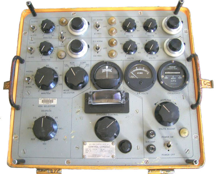
MC-1 Magnetic Compass Calibration Set
similar to AN/ASM-344
&
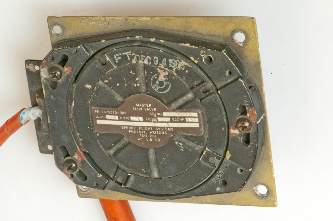
Sperry Master Flux Valve p/n 2575570-902

&
Many aircraft (and other vehicles) have a heading system that is a combination of a number of different sensors all working toghther to tell, at any instant, the heading. One of these is the magnetic heading sensor. Typically an electronic type like a flux gate magnatometer. In order to verify that the magnetic sensor on an aircraft is correct you need a calibration standard for magnetic filed.
One of the stickers on the yellow flight linc box says:
"Air Force Metrology
and Calibration
Program/ Base
Measurement Standard"Compass Systems & Aircraft Types
From TM 11-4920-292-15 pg. 163
Compass System Aircraft Type AN/ASN-13 & ID-567
AN/ASN-43 & ID-998/ASN
AN/ASN-43 & ID-1351/AU-1A U-8D
AH-1G, CH-47A, CH-54, UH-1B, UH-1C, UH-1D, UH-1H and U-21
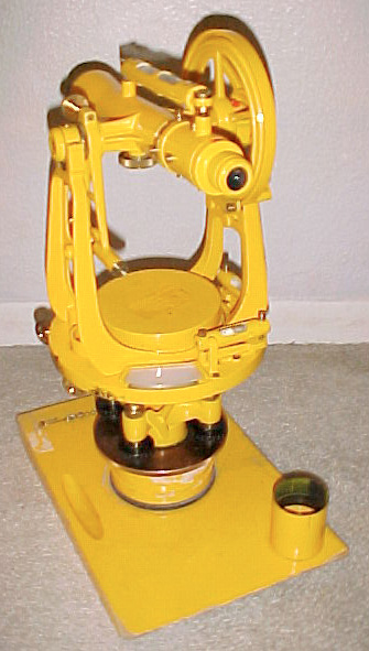
OH-6AC-12 U01A, U-6 and U-8D J-2 CH-47A, UH-1B, UH-1C, H-1A, U-6 and U-8D MA-1 OV-1 and U-8 Every year or two the Flux Valve is removed from the aircraft and mounted on a tripod. It is compared to the Magnetic Azimuth Reference Detector. This is done by using a surveyors transit that has had the needle type compass replaced with another Flux Valve.
The Flux Valve in the transit does not need to be calibrated, it is just used as a Synchro generator to repeat the angles turned by the transit. The Magnetic Azimuth Reference Detector is used to sense the Earth's Magnetic field which changes with time. In the manual many tests should be done within 30 minutes of a prior test so that changes in the Earth's magnetic field will not be a problem.
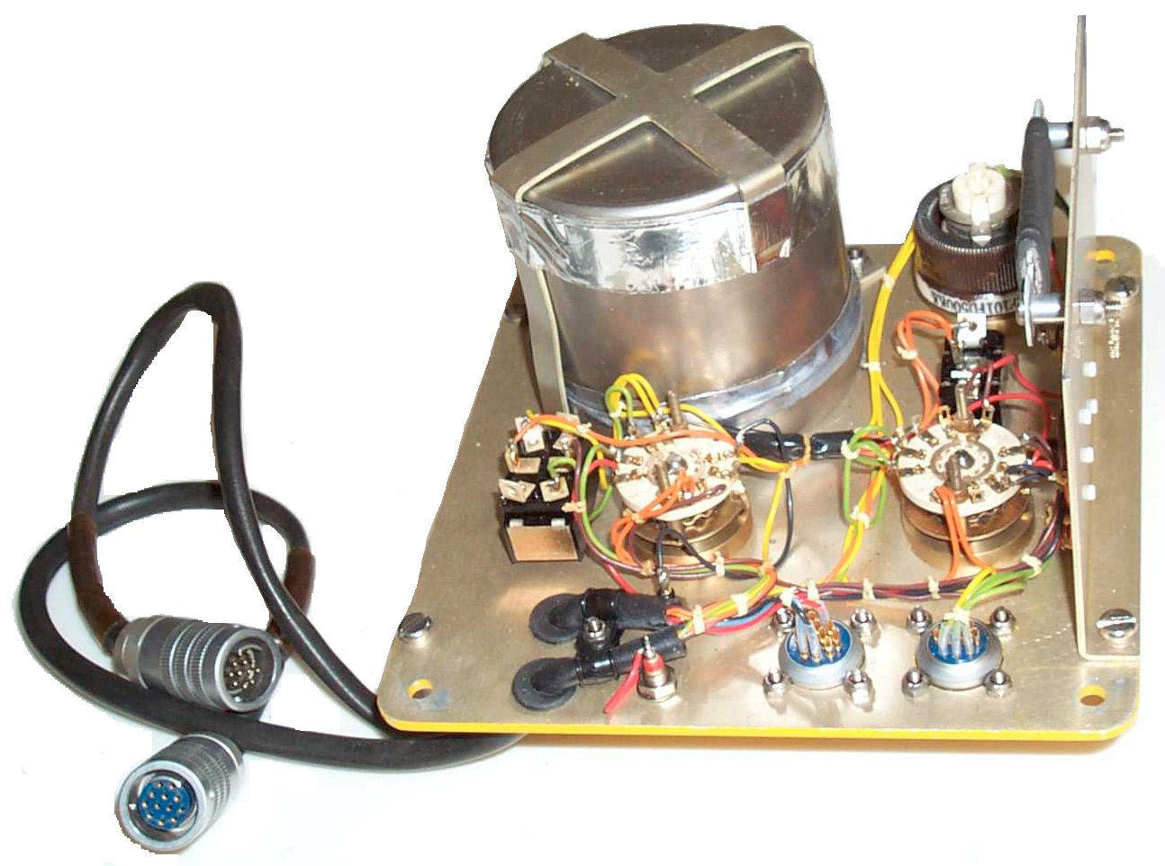
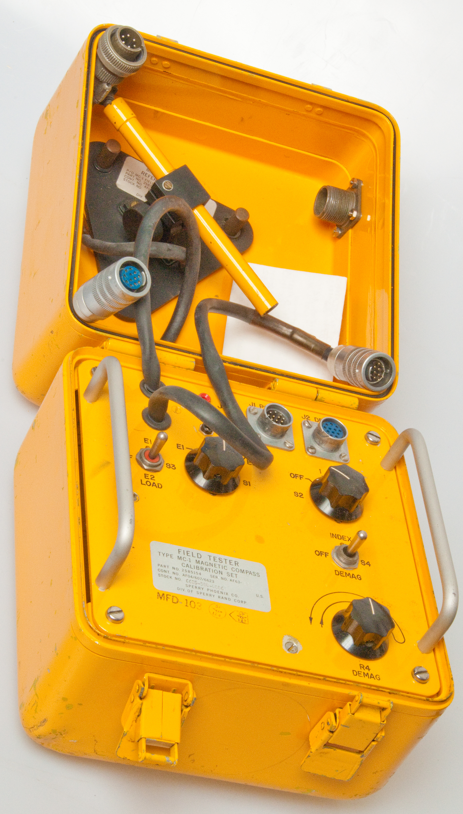
Box
The 8"x8" x8" flight line yellow box has the calibration set built into the bottom half. This is a Zero case p/n ZCC128-128A-D2540. Inside there is a cylindrical metal can about 3.5" diameter x 3.5" high. It appears to be magnetically shielded and contains a 3-axis sensor reffered to as "E1".
The cable that goes to it has wires:Switch S4 and power rheostat R4 are labeled "DEMAG" and the arrow on R4 indicates you should turn it from min to max and back to min which is a typical demagnetization technique. So one of the functions of the box is to demagnatize something, but what?
Switch S1 connects directly to the J3 (Red) and J4 (Black) Test Jacks.
- Black (color code 0) - sensor 1 output
- Brown (color code 1) - sensor 2 output
- Red (color code 2) - sensor 3 output
- Orange (color code 3) - drive coil
- Yellow (color code 4) - drive coil
- Green (color code 5) - common for output coils
- Position "E1" has J3 to two yellow wires and J4 to two orange wires
- Position "E2" has J3 to two green wires and J4 to a single brown wire
- Position "E1/E2" has J3 to the same two green wires as "E2" and J4 to a single yellow wire.
The other position of S4 is marked INDEX which means reading the output of the sensors . There are no meters or other output devices on the panel only a couple of tip jacks (Red and Black) that accept standard test prods, like on a DMM. These are used to read the 3 outputs. Just below the test jacks Switch S1 has positions E1, E2, E1/E2. Just to it's left is S3 with positions E1, OFF and E2 LOAD. To the right under the POWER and DEMAG sockets is switch S2 with positions OFF, 1, 2, 3. To the left of the test jacks two cables come out of the box and mate with the POWER and J2 DEMAG jacks. Maybe this test box is inserted into the aircraft system and is in series with the POWER and DEMAG parts of that system?
Internal fluxgate coil data (and most likley good for external fluxgate coil):
Schematic Drawing MC1.dwg (need Volo to view this drawing)
- Drive resistance 135 Ohms - this determines the current required for saturation
- Drive inductance - 500 mH
- Sense resistance 16 Omhs
- Sense inductance - 25 mH
Magnetic Azimuth Reference Detector
The "Magnetic Azimuth Reference Detector" is a seperate part that is stowed in the lid. I think this is some type of precise 3-axis magnetic field measuring standard. It has a small Berger telescope with cross hairs that can be moved up and down but not left to right. This might be used to adjust the body of the sensor to be aiming at a desired target on a compass rose made on the runway or apron. The two of the three mounting holes are slotted to allow a small amount of rotation before the MARD is locked down.The 1 foot electric cable is terminated with a mil spec 6 pin connector.Cannon MS 3106E14S-6P-S3. This connector does NOT mate with either of the two cables on the MC-1 panel or the two connectors on the two cables.
Pinouts of this connector:The label reads:
- A output 1
- B output 2
- C output 3
- D drive coil
- E drive coil
- F common ground for the 3 outputs
"Magnetic Azimuth
Reference Detector
P/O MC-1 Field Tester P/N 2585154
Cont No AF04(607)6623
Stock No. (blank)
Sperry Phoenix co.
Div of Sperry Rand Corp US"There is a standard letter size calibration sheet titled:
Hill Air Force Base Geomatic Center
Field Tester Report of MeasurementWith data for "Master Field Tester" and "Tester Field Tester"
The data is in units of degrees and minutes implying that level of accuracy.
Here's a photo of a Berger transit where the magnetic needle compass has been replaced by a flux valve.
These were installed on aircraft to provide magnetic heading information. The actual device is shown on a mounting plate that allows + or - 10 degrees of rotation for alignment.
When shaken you can feel something inside move as if it was suspended on a group weak springs.
The 7 pin connector is a Cinch Nuline MS24266R14 with cable clamp MS27291-3.
Ohms Table
Pin
1
2
3
4
5
6
7
1
0
15
15
OL
OL OL 15
2
0
30
OL OL OL 15
3
0
OL OL OL 15
4
0
150
OL OL 5
0
OL OL 6
0
V
7
0
There is little on the web about this. A U.S. Fluxgate Patent search has a large number of hits, many WW2 time frame Flux "Valve" patents relate to a sensor with a "Y" core and three sense coils. These were made to drive Syslen type indicators whose needle can rotate a full 360 degrees.It's not clear to me how the sensor is powered and connectod to the indicator. If you know please let me know.
For more see my Sensors web page, Magnetic section.
This is an Air Force instrument but may be very similar to part of the Army AN/ASM-339(V)1 Compass Calibration Set "Field Tester". The AN/ASM-344 looks very similar to the MC-1 shown in Figure 1-8A of TM 11-4920-290-15.Back to Brooke's Products for Sale, Sensors, Navigation, Military Information, Home page
TM 11-4920-290-15 includes the operator instructions for using the AN/ASM-339 system.The Drawings indicate that this is a "Y" core fluxgate with each leg at 120 degrees.
The main console is called the MC-2. Used to calibrate "swing" the A6 aircraft as an example. Also the H-46 copter(Navy Photo), C-130 used the MA-1.
Compass Systems & Aircraft Types
From TM 11-4920-292-15 pg. 163
Compass System Aircraft Type AN/ASN-13 & ID-567
AN/ASN-43 & ID-998/ASN
AN/ASN-43 & ID-1351/AU-1A U-8D
AH-1G, CH-47A, CH-54, UH-1B, UH-1C, UH-1D, UH-1H and U-21
OH-6AC-12 U01A, U-6 and U-8D J-2 CH-47A, UH-1B, UH-1C, H-1A, U-6 and U-8D MA-1 OV-1 and U-8 The MA-1 aircraft cmpass system test set consists of a table that can be rotated an a known rate for testing gyros and fluxgate compass?
TM 11-4920-292-20P has some pages showing the field tester and detector assembly with the scope.
TM 11 4920-292-40P has more details on the construction. It appears that the saturable metal core is a "Y" shaped "spider" with the legs at 120 degrees. On each leg there is a coil wound on a bobbin. I don't see the drive coil.
The AN/ASM-334 differs from the MC-1 mainly in that the AN/ASM-334 has two connectors on the front panel and uses a "y" cable whereas the MC-1 has to connectors and two short cables.The GA-277 Magnetic Compass Calibration Unit includes a Burger surveyors transit that is a part of this MC-1 system. eBay Item # 3108666067 .
[an error occurred while processing this directive] page created 13 July
2002.