|
 |
The first GPS satellite was launched in 1978 and the system was fully operational in 1993. This was a time period when there was a lot of GPS developments. Land surveyors developed methods of using the L2 carrier frequency even though they did not know the secret code to unlock the data.
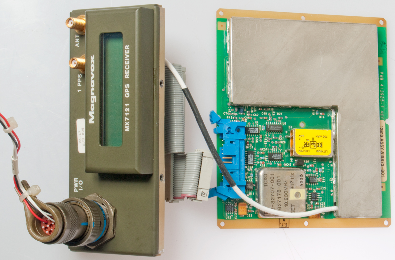
This is a GPS receiver made in the late 1990s by Magnavox. It came with an antenna made by Sensor Systems (p/n 627168-1 model S67-1575-29). It's an L1 civilian frequency only antenna. 1990 & 1991 date codes.
In 2025 discovered the MX 4400 series of GPS receivers. The brochure is dated 1987 so this model precedes the MX7221 by a few years.
Adding Patents paragraph.
Cable Connector: MS3476W12-10S
Pin
Function
A
+6 - +15 VDC
C
Ground chassis
D
Data
E
Data
B, F, G, H, J, K
nc
The screens are in order top to bottom:
-
25 JUL99 00:00:00
0SAT STS TFOM 9
SELF-TEST IN
PROGRESS
O3APR05 00:00:18
0SAT STS TFOM 9
Sensor Systems p/n: 627168-1 model: S67-1575-29 is not on their web page.
Looks like an L1 (1575) only antenna.
Dated: Mar 26 1991
TNC jack.
RF & Front Panel
Note: Dead yellow LTC-7PN Lithium battery
CPU 80C186
U10 & U12 ROMs marked V6.17
implying developed firmware
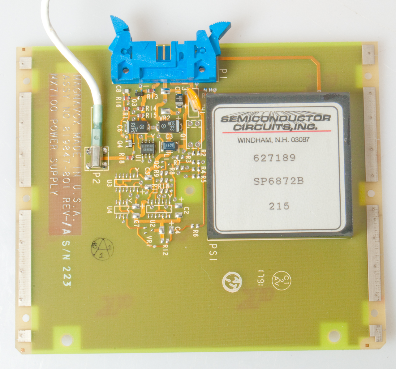
Power Supply & 1 PPS Output
Magnavox - Richard G. Keegan went to work for John Deere after leaving Magnavox and has many patents relating to GPS on tractors.
5040240 Receiver architecture for use with a global positioning system, Richard G. Keegan, Magnavox Government and Industrial Electronics, 1991-08-13, -
Defines F=5.115 MHz (half the now popular frequency of 10.23 MHz).
The received L1 signal is 308 *(F + d) where d is the Doppler offset of the satellite being received. Received L2 = 240 *(F + d).
All the LOs in the receiver and the sampling clock are derived from a single oscillator thus making for phase coherent signals.
DAGR
PLGR
Navigation
Back to Brooke's PRC68, Products for Sale,
Navigation, Military
Information, Personel Home
page page created 19 March 2013.