PLGR GPS Family
©Brooke Clarke,
N6GCE
HNV-560c
Basics
Marking
Versions
Description
GPS Comparison Table
Applications
Time
SINCGARS TOD
Have Quick TOD
Target Finder (Gun Laying)
Status
Batteries
Antennas
Mounting
Computer Interface
Key Load Cable
External Power
Human Factors
What Goes Wrong
Manuals
PLGR II
Other Military GPS Models
Crypto Keys
GPS Patents
Links
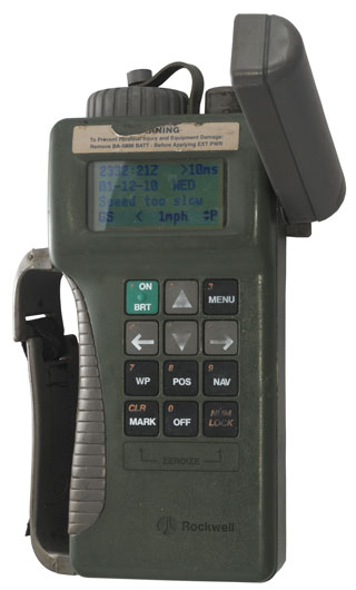
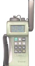
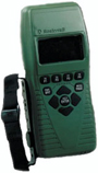
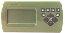
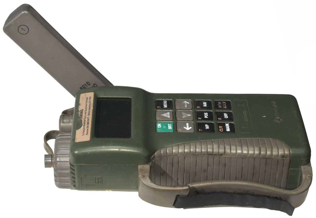
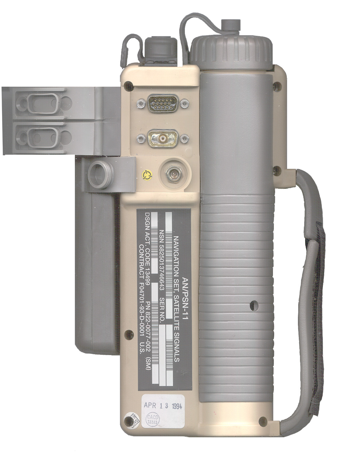
HNV-560c Military Version
Note: The civilian version is
marked HNV550 (Hughes NaVigation 550 or maybe 500).
Official word from Rockwell:
The HNV-560C 822-0077-103 is the
Military AN/PSN-11 (PLGR).
The HNV-500A 822-0255-103 is
the commercial version.
|
Power On:
Copr. 1989-1996
Rockwell Intl
613-9868-005 |
|
Label:
Receiver, Radio
Type No. HNV-560c
Ser. No. 1111xx
Part No. 822-0077-103(SM)
|
<move>
select
STATUS
SETUP
INIT
TEST
HELP
<MORE>
|
TARGET
new
view
guide
clear
wpcopy
define
calibrate
|
STS
Self-Test OK
Internal antenna
Vehicle power
|
DATA-XFR
SV-SEL
DOP-CALC ALERTS
SINCGARS KOI-18
|
FINDER
Signal lvl: 160
[][][][][][][][][][][][]
Min
Max
Center
Mark
Quit
|
BATTERY:BA-5800
non-rechargeable
00h00m used RST
24h04m left
|
CUSTOM NAV
COORD SYSTEMS
TARGET
FINDER
|
Receiver Version
INFORMATION
t:005E
p:005E
CLEAR
|
Diff GPS none
1PPS-IN none
SERIAL none
BRT on 0%
|
|
Config Status
SW:613-9866-005
HW:1E11 |
SV 21 29 18 05
CN 36 33 35 00
CD CA CA CA CA
ST T
T T T
|
SETUP Modes:
CONT, FIX, AVG, TIME, STBY, 2dTNG
3dTNG, RHRSL, CONT
|
STS
GPS good
Self-Test OK
internal antenna
Vehicle power
|
SV 21 18 29
ST OK OK
OK
AZ 334 215 136
EL ^70 ^58 V54
|
|
|
SV 02 SPEC MSG
P0G9UYD5VCM4JSB2
DS.7BE
|
at power on
|
Pressing MENU |
Pressing MENU |
<move>
select
STATUS
SETUP
INIT
TEST
HELP
<MORE> |
DATA-XFR
SV-SEL
DOP-CALC ALERTS
SINCGARS KOI-18
<more> P
|
CUSTOM NAV
COORD SYSTEMS
TARGET
FINDER <more> P
|
| Pressing MENU |
|
|
<move>
select
STATUS
SETUP
INIT
TEST
HELP
<MORE> |
|
|
|
|

|
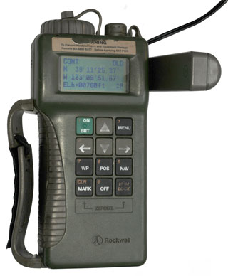
2 Dec 2010 1647
GMT/UTC/Zulu
39d 11m 24.76sec N
123d 09m 51.26sec W
+00873ft above Mean Sea Level
tracking 2 satellites indoors!

The Time Figure Of Merit (TFOM) in the upper right
corner is showing +/-100ns whenever I look at it even though
the receiver is indoors. In some indoor locations that
display goes to +/-10 or 100 ms.
|
|
|
A different HNV-560c has software: 613-9869-005
Setup Modes: CONT, FIX, AVG, TIME, STBY, 2D-TRN, 3D-TRN, RHRSL
i.e. the same as my HNV-560c with software 613-9866-005
A different HNV-560c has software: 613-9544-007
Setup Modes: CONT, FIX, AVG, TIME, STBY, 2dTNG, 3dTNG, RHRSL, CONT
This unit in FIX mode was displaying a 1991 data, but the correct
time. Changing to CONT mode . . . TBD
PLGR AN/PSN-11
13 Feb 2006 - PLGR taken by the DOD as evidence. It was
stolen. I'm out what I paid.
 .
.  .
.  .
. 
 .
.
Basics
Precision Lightweight GPS Receiver
has
SPS
and
PPS
capability,
made
by
Rockwell
Collins
5 channels C/A, P, Y codes
Baseline II - tan case firmware 613-9854-003 or 613-9854-004
NSN 5825-01-374-6643
Baseline III - green case firmware 613-9854-008 or 613-9854-009
PLGR+96 613-9854-006
(these versions as of Feb 2003)
Brooke's Comment - Although this is a P code capable
receiver, since SA was turned off May, 2, 2000 it's questionable
how the position accuracy compares to a civilian 12 channel
receiver like the Garmin
hand held units. For military operations the Anti Spoof
(AS) part of using a key may have an advantage against a
sophisticated enemy, it's of little use against a not so
sophisticated enemy. Hopefully the GRAM will be a 12
channel receiver.
Follow-up comment: This 5 channel GPS receiver is the
most sensitive I've worked with. It will lock up on
signals that are right on the horizon whereas the Garmin 12
channel III Plus and the Motorola 8 channel VP Oncore
receivers need the sat to be maybe 10 to 15 degrees above the
horizon.
Marking
The military units are marked
"PSN-11 (see the row below "mil") or HNV-500 (see the row below
"civilian")
Versions
PLGR+96 describes a software change
not specifically a hardware change to Baseline PLGRs.
The PLGR II and VPLGR II are improved hardware over the basline
PLGRs.
The VPLGR was for use in Vehicles and seems to have addressed some
of the
human factor problems. In addition
it's a dual frequency receiver.
The PLGR, PLGR-II and VPLGR-II are all currently out of
production.
In the UK the PLGR-III is called the
Specialist Personal GPS Receiver (SPGR).
Ver
|
Baseline
|
Baseline II
|
Baseline III |
Baseline
IV |
PLGR+96 |
PLGR II
|
VPLGR II
|
Photo
|
|
|
|
|
Years made
|
Sep 1993
- 2005
|
Apr 1995
|
|
|
FY03
|
|
|
Freq
(Chan)
|
L1 (5)
|
L1 L2
(12)
|
L1 L2
(12)
|
Mil
|
AN/PSN-11
|
AN/PSN-11
(V)1
|
HNV-560c
|
|
|
|
|
|
Civilian
|
HNV-500A
822-0255-002
|
HNV-500B
822-0255-003 |
HNV-550c
|
|
HNV-500C
822-0255-103 |
|
|
Case
|
tan |
green
|
tan
green
|
green |
|
green |
green |
NSN
|
5825-01-374-6643
|
5825-01-395-3513 |
|
|
|
|
|
R.C. p/n
|
523-0777-289CP
523-0777-289PP
523-0777-334CP
523-0777-334PP
523-0777-643CP
523-0777-643PP
523-0777-643W
523-0777-645CP
523-0777-645PP
523-0777-645W
|
822-0077-002
|
822-0077-003
T
822-0077-103 G
822-0077-103(SM)
822-0255-003 G
|
822-0255-103 |
822-0077-xxx
(PPS)
822-0255-xxx (SPS)
|
822-1096-xxx
|
822-1365-333
|
Firmware
|
4b.1 613-9854-xxx
613-9854-005
|
4c.2, 4d.3
613-9544-xxx
613-9544-101
613-9868-008
|
613-9544-001
613-9544-002
613-9544-003
613-9544-004
613-9544-005
613-9544-006
613-9544-007
|
613-9544-002
613-9544-003
613-9544-004
613-9544-005
613-9544-006
613-9544-007
|
sw
upgrade
613-9854-006 |
|
|
Battery
Life
|
|
10 hr
|
20 hr
|
|
27
|
24
|
24
|
LCD
|
Character
|
Character
|
dot matrix
|
Setup
Modes
|
|
CONT,
FIX, AVG
TIME, STBY, TRAIN
|
CONT,
FIX, AVG, TIME
STBY, 2D-TRN, 3D-TRN, RHRSL
|
|
|
|
|
Literature
|
|
Delta
Doccumnt for the PLGR 5/1996
PLGR Made Simple 11/1997
TB 11-5825-291-10 9/1995
TB 11-5825-291-10-2
TB 11-5825-291-30 7/1997
TM 11-5825-291-10 9/1995
TM 11-5825-291-13 9/1995
M 11-5825-291-13-1
ICD-GPS-154 6/1999
|
|
|
|
|
|
In the UK there is a Rockwell GPS
receiver called the Specialist Personal GPS Receiver (SPGR) that
may be a variation on the PLGR. If you have one
let me know. The 3.5" x 5.5"
plastic instruction card is dated 1997.
Description
When I wrote this web page in 2003 I
thought (ass-u-med) that the PLGR was a dual frequency
receiver. But now in 2008 while learning about the DAGR
discovered it's only a single frequency receiver.
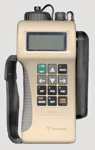
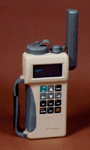
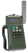
The Standard PLGR (first used in 1993) has a tan case and the
Enhanced PLGR has an OD case.
GPS Comparison Table
|
Manpack1
AN/PSN-8
|
SLGR
PSN-10
|
Transpak II
|
SAGR
AN/ASN-169
|
PLGR
AN/PSN-11
|
DAGR
AN/PSN-13()
|
Frequency
|
L1?
|
L1
|
L1
|
L1
& L2
|
L1
|
L1
& L2 |
# of GPS
Channels
|
3?
|
3
|
6
|
6
|
5
|
12
|
SA AS
|
no?
|
no
|
no
|
SA
& AS
|
SA
& AS
|
SA
& AS |
Display
|
?
|
4 Line
Text
|
4 Line
Text |
4 Line
Text |
4 Line
Text |
?x?
Graphic
|
Weight
|
17#
|
4#
|
4# |
4# |
3#
|
<1#
|
Antenna Voltage
|
?
|
5
|
5
|
5
|
5
|
3.3
|
Note 1 - This was packaged using a method similar to the
PRC-25 or
PRC-77
radios. A similar manpack navigation receiver was the
PSN-6 Loran Reciever.
Applications
GPS has two classical applications: position and time
and the PLGR is used for both of these.
Position
Provides position information using both L1 and L2 with SPS and
PPS capability thus will provide position in combat conditions.
Note: The PPS Anti Spoof capability is effective
against spoofing, but in my opinion it's more likely the enemy
would use a jammer rather than a spoofing transmission. A
jammer will just cause the GPS receiver to not lock hence it
will not update the position.
Note 2: The PLGR seems to choose satellites that are
dispersed horizontally, rejecting a satellite that is
overhead. This may be part of the SETUP and depends on
what you are trying to learn. This PLGR mode would be
good for Lat & Lon but poor if Elevation was important.
Once the satellite almanac has been loaded and you are in Figure
Of Merit (FOM) mode 1 (the best condition) then in SETUP you can
change from CONTionious mode to STandBY mode then into AVeraGe
mode. (You can not go directly from CONT to AVG mode, but
must first go into STBY mode. Then in the POSition menus you
will find a screen that shows the averaged position. At my
location it shows:
|
|
PLGR
|
PLGR
|
UT+ Carrier phase
|
Surveyor
|
|
Lat
|
N 39:11:24.32
|
N 39:11:24.53
|
N 39:11:24.692
|
N
39:11:24:5833
|
|
Lon
|
W 123:09:49.79
|
W 123:09:50.18
|
W 123:09:50.548
|
W
123:09:50.4842
|
|
Elevation meters1
|
250
|
273
|
249.7
|
280.45
|
|
# averages
|
1510
|
32400*
|
na
|
na
|
* The averaging function stops at 32400.
Note1 - There appear to be two different elevations
(either around 280 or 250 meters), this is probably my error or a
difference in the elevation reference.
Time
Modern frequency hopping radios like the SINCGARS
VHF low band radio and the "Have Quick" UHF military aircraft
radios both depend on very accurate time as part of the frequency
hopping scheme. The PLGR supports both of these radio
systems in terms of precise time synchronization. It has a
10 micro second resolution.
There are two ways to use the Have Quick time code. With a
direct wire connection or over the aircraft radio. When over
the radio the code needs to be send as audio tones rahter than as
DC voltage levels.
Have Quick II has a bit period of 600 us and an HCMOS output
level.
The Have Quick time code specifications are:
SS-110990
ICD-GPS-060 - uses the MIL-STD-1553 aircraft bus to distribute
time
STANAG 4430
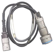
SINCGARS TOD
The SINCGARS Time Fill cable is the Rockwell p/n 426-0141-070 (NSN
6150-01-375-8666)
It's a 6 contact U-229 on both ends type cable just over 3 meters
long indicating that the radio can be left in a vehicle and the
PLGR moved to somewhere outside (maybe even a man standing on the
roof?).
The RT-1439 and RT-1523 will NOT
accept time from any fill device, like a PLGR.
The RT-1523A and newer SINCGARS
radios accept time fill.
Have Quick TOD
The NSN 6150-01-375-8665 CAGE: 13499, P/N: 426-0141-040 Cable is
for loading the Time Of Day into a Have Quick RT-1319 225 - 400 MHz radio.
This is for the frequency hopping, not the voice crypto. The
radio connector is a Bendix-9137 JMS27467T15B35S
1467830 only sockets 10 and 11 are connected. The GPS
receiver connector is a standard military AUDIO MC329G2 6 pin
type.
RT-1319
J____ pin #
|
PLGR
J1 pin #
|
Function
|
10
|
E
|
data
|
11
|
F
|
return
|
One application of the RT-1319 is as a part of the GRC-206 system which uses the O-1814 Rubidium Frequency Standard to
maintain Time Of Day for the Have Quick part of the UHF air band
radio. Pin 11 related to the RT-1319 is ground.
Have Quick data protocols comes in a number of flavors. They
all start with the basic Time Of Day data then there are
additional data fields for Day Of Year, and another that adds Time
Figure Of Merit after DOY. SINCGARS has a slightly different
way of computing the calendar. So there are different time
fill formats and or signal levels available on the PLGR J1 and J2
connectors.
Also see the O-1814/GRC-206 Rubidium
Oscillator web page for more on Have Quick time code.
Target Finder (Gun Laying)
TM 9-6675-347-13&P (pdf)
Operator, Organizational and Direct Support Maintenance Manual for
Gun Laying and Positioning System (GLPS): M67
(NSN 6675-01-430-1965) (EIC: 3XA)
31 October 2000
The M67 consists of:
Laser Rangefinder MRF2000-2 covering 30 to 2500 meters,
T502S Theodolite
-
The combination of Theodolite and range finder is called a Total
Station (Wiki) in
the surveying
business.
SKK3-08 Gyroscope (for North Finding)
PLGR GPS receiver and related poles and tripods.
The heart of this system is the North Finding Gyro. The PLGR
is an accessory that allows finding Lon & Lat.
The Target Finder function in the PLGR is based on Way Point
calculation using either Slant Range Calculations (SR-CALC) or
Range Calculation (RNG-CALC).
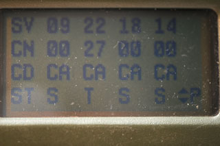
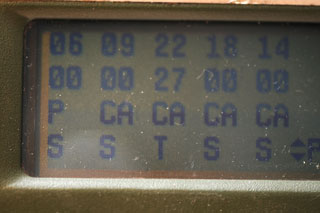
Status
This is something I don't understand. When viewing the
status of the received satellites (MENU -> Status) then up or
down arrow to this page:
|
PLGR Status page with ID
column showing 4 satellites
SV is the Space Vehicle number
CN is the Carrier / Noise ratio, ie. signal strength
CD is CoDe: CA, P or Y
ST is Status:
I = Interference
R = Recovery
S = Search
T = Track
Photo taken using built-in antenna indoors so SV#s 06, 09,
18 and 14 are in Search status.
|
|
Left arrow showing all 5
channels being tracked.
But the left most channel always seems to be in P code
mode. Is this a bug in the PLGR or . . . let me know.
Sometimes when the helmet (or any external) antenna is
connected all the CoDe values are CA. But right
after a new satellite shows up in channel one it's code
shows as "P" for example SV 09 showed P but when SV06
showed up it was CA. Channel 1 seems to be used to
search for satellites rather than track them and so
defaults to P mode.
|
Batteries
The tan case PLGR draws about 150 mA so you can
estimate battery life. The green case PLGR draws about 75
ma, 1/2 the current of the tan case units. The OD green
case PLGR is supposed to draw maybe 1/2 the current.
Main
This is a plastic cased receiver and they have done the same
thing that was done in the SDU-30
marker light. That is to require a special battery with
both contacts on the same end. By doing this they don't
need to use a metal cap and can keep the power circuitry
shorter. But the problem is then placed on the battery
vendor to bring both contacts to one end..
6 Volt Lithium Sulfur dioxide BA-5800A/U NSN
6135-01-440-7774.
The old BA-5800/U NSN 6665-99-760-9742 is obsolete.
Probably because the lack of a charging prevention diode
allowed it to explode when using in equipment, like the PLGR,
that has provision to charge the battery.
If you use AA-alkaline or AA-lithium (? chemistry)
batteries, you'll need eight of them, plus battery holder,
NSN 6160-01-3854358.
BA-5800 Battery Adapter
holds 8 each AA cells and can be used with either 4 or 8
cells to supply 6 Volts nominal..
BB-2800 (NSN: 6140-01-490-5372) is a Li-Ion rechargeable
battery and can be charged using the PP-8498/U charger that
comes in what looks like a small suitcase very similar to
the PP-8444()/U. Supposed
to be fielded in early 2003.
Ni-MH rechargeable (NSN: 6140-01-400-2902). The PLGR
has a charging circuit for this battery and maintains it
charged when external power is connected. GPS
Pathfinder magazine Issue
10 No. 3 says that only this particular battery will
be charged. But they don't say how that's
accomplished. It may be that in July 2003 the
BB-2800 was not yet fielded and so there was not any
rechargeable BA-5800 size battery. Note that the
BA5800 battery adapter contains combining diodes and will
not allow charging current into the AA cells. This
means it's safe to use as a backup while an external power
supply is being used.
Ni-MH cells are not amenable to "trickle" charging.
If a DC trickle charge is used the battery will overheat and
it's life may be as short as a few months. The proper
way to maintain a Ni-MH battery is to use a pulse method
where the duty cycle is about 1/500.
If you know more about the charger in a PLGR please let me know.
Memory
This Hold Up Battery keeps the crypto key alive, almanac,
ephemeris and error log. This AA size 3.6 Volt Lithium
battery has conventional construction with positive on one end
and negative on the other end. The battery compartment cap
is metal. Positive in first, negative is cap/spring.
Because the error log is maintained by the memory battery you
should leave the memory battery installed when returning a unit
for repair.
3.6 Volt Lithium (? chemistry) NSN
6135-01-301-8776
Tadrian
TL2100/S
Saft LS-14500
Radio Shack 23-037
(Replaces Types TL-5104 & TL-2100) 3.6V Lithium
Market:
Tadiran
TL-2100
3.6 Volts Lithium
Note
Although this battery is the size of a standard AA cell, a
standard AA cell is 1.5 Volts and is way below what a 3.6 Volt
cell is even when dead. Don't bother trying a 1.5 AA
cell, it will not work.
SAFETY
Note there are 3 ways a PLGR can be connected to a military
vehicle battery system.
(1) connect across both batteries for a 24 volt power
source. This is OK
(2) connect across the 12 volt battery that tied to chassis
ground. This is OK.
(2) DO NOT DO THIS!
connect across the 12 volt battery that's not
grounded. This will cause the Memory battery to
explode! DO NOT
DO THIS!
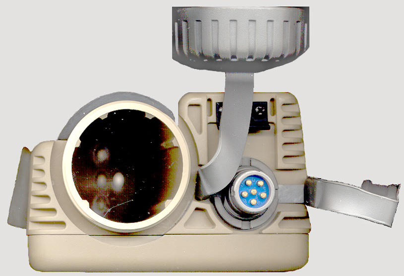
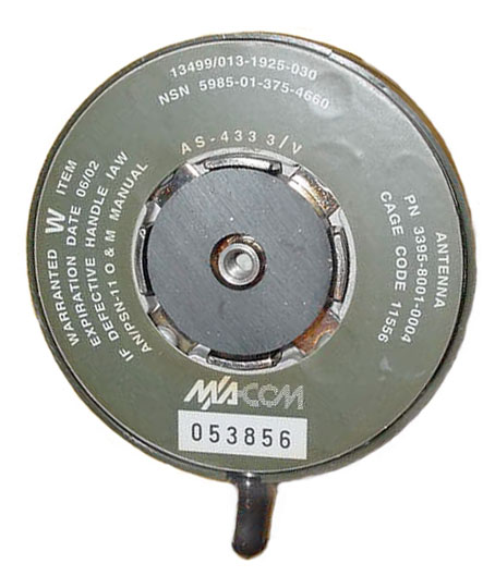
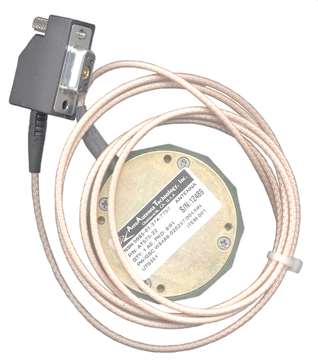
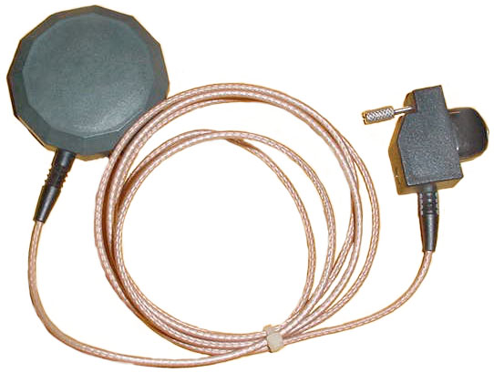
Antennas
There is a permanently attached antenna that probably is
a quad helix. In addition you can connect an external
antenna to the connector on the back. Helmet Antenna
AS-4334/U and Remote Antenna AS-4333N are made by Spectra Systems, Inc.
FL.
The PLGR uses 5 Volt antennas. The newer DAGR uses 3.3 Volt
antennas.
The PLGR is a L1 frequency only receiver, yet many of the antennas
are dual frequency (L1, L2). Why is that? Let me know.
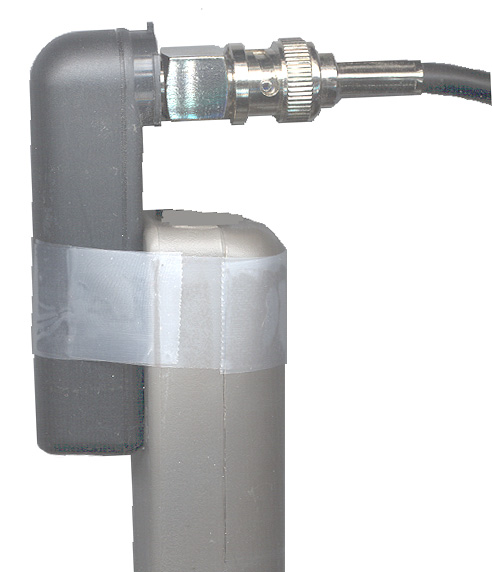
Indoor Operation Without the Special Antenna Connector
 In order to use my roof mounted
house GPS antenna and 4 way power divider
to feed the PLGR GPS signals without the special RF PLGR cable, I
just used the antenna from my Garmin GPS III Plus. It looks
like a miniature PLGR antenna and even has a flat side just like
the PLGR. By taping the Garmin antenna to the PLGR antenna
the PLGR works very well. In fact the PLGR will lock onto
signals that my Motorola VP Oncore receivers can not lock onto.
In order to use my roof mounted
house GPS antenna and 4 way power divider
to feed the PLGR GPS signals without the special RF PLGR cable, I
just used the antenna from my Garmin GPS III Plus. It looks
like a miniature PLGR antenna and even has a flat side just like
the PLGR. By taping the Garmin antenna to the PLGR antenna
the PLGR works very well. In fact the PLGR will lock onto
signals that my Motorola VP Oncore receivers can not lock onto.
The connector needed to make up an external antenna is a Combo-D
series made by Positronics Industries, model CBD5W1F20
00X with the coax insert FS4202D
Mounting
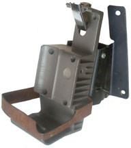
The actual mount is the plastic part
with the four mounting holes. There is an adjustable angle
support bracket and a security loop in addition to the mount.
p/n 986-0645-001
NSN 5975-01-375-1302
Computer Interface
The PLGR has a 15 pin "D" series connector that is the
same type used on PC video connections. The digital
interface is in RS-422 protocol thus providing greater distance
and higher speed than can reliably obtained from RS-232.
There is also a standard RS-232 interface for use with a PC.
There are also timing inputs and outputs to support
precision time transfer.
One use for this interface is to couple the PLGR with a military
VHF low band radio like a SINCGARS
or Bowman. This allows the
position of the radio to be sent, automatically in some
cases. It also allows traget coordinates or Close Air
Support messages to be sent (requires bearing and distance between
user and target typically from a Laser Range Finder).
The data protocol is defined in ICD-153. It's a binary
protocol and an expanded version is used for the DAGR.
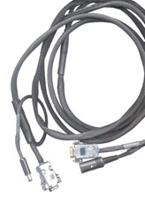
Serial Cable
 Marked (items
shown as <...> are in Hewbrew::
Marked (items
shown as <...> are in Hewbrew::
13499ASSY426-0141-090
<5 letters> PLGR <4 letters> <3 letters>
<3 letters> 3 <4 letters> 4263-<2 letters>
3177-00113 <4 letters>
PLGR to PC Cable
NSN 6150-01-375-8664
p/n 426-0141-010 US (-090 Israel)
eBay cable is wired as shown below and reported to send
NMEA 4800 8N1 data to a
PC.
When I run Hyperterminal at 9600 8N1 with no flow control I get
gibberish once every second. At 4800 baud I don't get
anything. This with the PLGR set for Serial: Standard.
This hex taken using LabView looks very much like the Rockwell
binary data below.
FF81
0300
3D00
0080
C1FD 7C49 5B8D 56DD DEE1
A748 3794 ADBA 93C7 0000
0400 2F40 5E1A 09C1 5993
25CB C147 7CCB BCEB 744B
3EAE 8444 7291 7044 10BB
5DBD 6BD4 9ABD D1F1 183C
54C1 0000 0000 0000 0000 0000 0000 0000 0000 0000 0000 0000 0000
8F3F 3C2D 851B 1B21 271B
15 Pins
(PSN11)
DB9 connector (PC
15 ----------------------------------
3
14 ----------------------------------
2
2
---------------------------------- 5
(1, 4,6,8 linked together on the
DB9)
(3 and 13 linked together
on the 15 pins connector on PSN-11 )
Reprogramming Cable
p/n
9434308-10, CAGE 55928, 09/06/2000 NSN 6150-01-382-1551
This is an octopus type cable with a DB type 15 socket and a
765K plug on one end to attach to the PLGR (no threaded
connector for this application) and at the other end there is a
standard 9 socket DB serial connector that connects directly to
a computer, but in addition there is also a DIN type 5 socket
connector that connects to a power supply to power the PLGR.
( Not sure about this: so that a battery is not needed on the
PLGR, as would be the case when it's returned for
reprogramming.)
It's more likely that the 12.0 +/- 0.5 Volt external power
supply is required to programming the EPROM used in the PLGR (
Wiki).
The DAGR can be reprogrammed with a simple DAGR/PLGR to
DAGR/PLGR serial data cable, i.e. the DAGR does not need the
programming voltage.
PLGR
15 pin
|
PLGR
pwr
|
Computer
DB-9f
|
Computer
DIN
|
1 PPS in
1
|
|
|
|
1 PPS in rtrn
2
Unit Ground
|
|
Gnd
5
|
|
Gnd
3
Unit Ground
|
|
|
|
RS-422A out
4
|
|
|
|
RS-422B out
5
|
|
|
|
1 PPS out
6
|
|
|
|
HQ out
7
|
|
|
|
Rmt not on
8
|
|
|
|
RS-422 A in
9
|
|
|
|
RS-422 B in
10
|
|
|
|
1 PPS out rtn
11
|
|
|
|
Vprog in
12
|
|
|
3
|
serial data buffer not enable
13
|
|
|
|
RS-232 Tx
14 |
|
Rx
2x
|
|
RS-232 Rx
15 |
|
Tx
3 |
|
|
ctr
|
|
5
|
Init Ground
|
outside
|
|
4
|
By tying the computer DB9
connector pins 1, 4, 6, 7(RTS) and 8(CTS) together the computer
thinks is has hardware handshaking (Request To Send from the
computer drives the Clear To Send input). A power
supply with a DIN 5 pin plug supplies both power to the PLGR and
the 12 Volts needed for the EEPROM programming. Looking
into the end of the DIN connector with the alignment notch at
12:00 o'clock the pins are numbered starting at 3:00 o'clock and
going clockwise: 1, 4, 2, 5, 3.
Since the programming voltage ground is completed through the
EXT power jack on the PLGR, the external power plug must be
installed, even of there is a main battery in the PLGR.
This cable should also work for use with the PC mission planning
software.
PLGR - 9600 baud, No Parity, 8 data bits, 1 Stop bit
(9600 N,8,1)
LabVIEW
Using a simple LabVIEW program and the above
programming cable I can see data coming out of the PLGR.
I used the Collins MicroTracker Designer's Guide binary data
format information, which seems to match this data. I
expect that each manufacturer has their own GPS binary data
protocol that's used on all their products. That's the
case with Motorola and Trimble.
There is a simple message that is sent out about once every 5
seconds, it is in Collins binary format:
Frame Sync = 81FF hex
Message ID = 0080 hex
Word count = 0001 hex
Flags
=
8000 hex
Chk sum = F8FD hex
message = 0006 hex
msg chk sum = FFAF hex
=========== next frame ==========
FS = 81FF
ID = 00FD
WC = 0000
Flgs = 9000
cs = ED04
no mesage, no message chk sum
=========== next frame ==========
81FF
00FD
0000 another empty frame
9000
ED04
============
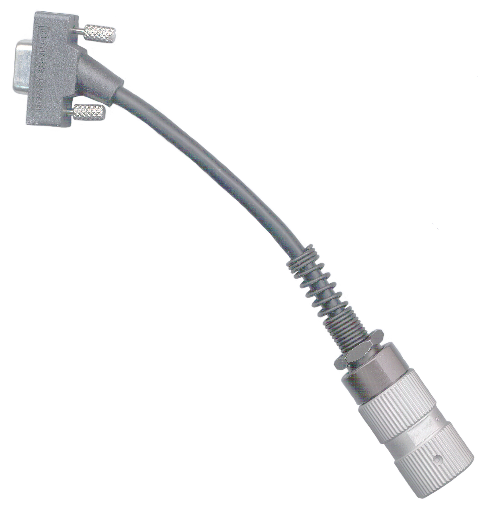
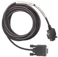
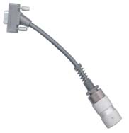
Key Load Cable
 I got
this on eBay advertised as a "Rockwell PLGR-II GPS Crypto Adapter
Cable".
I got
this on eBay advertised as a "Rockwell PLGR-II GPS Crypto Adapter
Cable".
The unopened plastic bag has a label: 12499ASSY-988-3116-001
REV A (this line is also molded into the DB-15 connector plastic)
MFR TSE-J 7-24-98
p/n 988-3116-001 is listed on the PLGR-II+ADK
Rockwell web page as a "crypto adapter cable", but is not listed
on the PLGR+96
web page.
The cable itself has a DB-15(f) connector on one end and a 329G2
6-pin AUDIO connector on the other end. The AUDIO connector
mates with "J1" on top of the PLGR, or with a crypto fill device.
The most likely way this is used is to connect the AUDIO connector
to the fill device and the DB connector to the PLGR.
Note that most computers have a DB-9(m) connection and so this
cable will not fit. It will connect to the end of a computer
monitor cable, i.e. this is the same connector that's on a
computer for the video monitor.
The DB-15(m) connector DOES fit the J2 Data Connector** on the
back of the PLGR.
Cable Wiring
AUDIO
Pin #
|
DB-15m
Pin #
|
PLGR J2 Function**
|
A
|
10
|
RS-422 A Input
|
B
|
9
|
RS-422 B Input
|
C
|
13
|
Serial Data Port Buffer Not Enable
|
D
|
7
|
Have Quick 1 PPS TTL output
|
E
|
8
|
Remote On when Ground
|
F
|
n.c.
|
|
n.c.
|
3, 4*
|
3 = Ground
|
| n.c. |
3, 4*
|
4 = RS-422 B Output
|
n.c.
|
1, 2, 5, 6, 11, 12,14, 15*
|
|
* The connection between the DB-15
pins 3 and 4 (and nothing on pins 1, 2, 5, 6, 11, 12,14, 15) may
be part of a system of telling the key load equipment (or PLGR)
what device is connected to the other end of the cable?
** The J2 connections shown may or may not make sense for a crypto
fill connection. It's common that more than one function is
serviced by the same connector.
External Power
Takes 9 to 32 Volts, positive on the center contact. BUT
the negative lead must be ground, it can not be higher. If
the "hot" battery in a dual battery system is used for the
PLGR smoke will come out of the wiring. THe PLGR has
an internal switching mode power supply so it's current draw
varies with the input voltage. At 9 Volts in the current is
about 200 ma and at 27 VDC in it's about 80 ma, in either case
about 1.9 watts.
The manual says the mating connector is a Switchcraft RA-765
which is part of a cord assembly. The 765K
(Red handle) or 760K (Black handle) pug do fit
properly. The "K" suffix means a threaded
locking ring, the parts without the locking ring are 765 or
760.
The Radio Shack 5.5 x 2.5 mm 274-1573
DC Power Plug can be used for external power. But it
does not have the screw down locking collar and so may very
well fall out.
The Switchcraft 761K does NOT fit, it's too long.
Switchcraft parts with an "S" prefix have a Small hole and
will NOT fit the PLGR.
 NSN
6150-01-375-8661 p/n 426-0144-010
NSN
6150-01-375-8661 p/n 426-0144-010
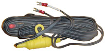
Collins DC Power cord with spade lugs one end and the special PLGR
screw lock connector on the other end. Only one line
fused. I don't know which lead is fused. If it's in the hot
(+) lead there's a possible problem connecting the two leads to
the "hot" 12 Volt battery in a 24 volt system then connecting
something grounded to any ground point on the PLGR. This
lets the smoke out of the PLGR!
WARNING
There
are
no
fuses
inside
the
PLGR
so
when
using
external
power
you
should
supply a fuse, or better fuse both leads.
SAFETY Do Not connect the external
power cable to the top (non grounded) battery in a military
vehicle 24 volt system. Doing so will cause the memory
battery to explode.
Hint When using external power
it's good to also have a main battery installed, although not
necessary. The reason is that if you have a power glitch in
the external power the receiver shuts down and restarts.
This is very time consuming and annoying but does not happen when
you have a main battery to ride out the external power glitch.
External Power Connector ,
Cigarette Lighter Plug & Power Pole to PLGR cables available.
Carrying Case
P/N: 021-0706-010
NSN: 5895-01-375-7528
- holds PLGR, remote antenna & cables, spare
batteries.
Human Factors
A number of problems:
- The LCD can only be read with your eye below the bottom
edge of the PLGR. You can not read the display when
looking down from the top, like when it's mounted on a
vehicle.
- The memory battery cap is very difficult to reinstall and,
being a seperate part is easy to loose.
- The use of non standard batteries is bad enough, but using
a "AA" size battery for the memory battery that's non standard
must cause a lot of problems. Too bad since there is
plenty of room in the box to use 3 each standard 1.5 V AA
cells.
- Non standard connectors on the rear panel for: external
power, digital I/O and antenna, these all could have been done
using standard connectors.
- case is larger than it needs to be, making it awkward to
carry.
- The displayed time is often wrong. Sometimes by one second
and at others up to 41 seconds off. There is no
indication that there is a time error.
Master Reset
If the PLGR fails to turn on, before returning for repair, try a
master reset.
Remove both the main and hold up batteries.
Short the external power connector center pin to it's shell for
a few seconds.
Install the correct 3.6 volt hold up battery and a main battery,
both checked to be sure they are good.
Press the green ON button.
On the very early versions of the PLGR it's possible that the
time displayed is off (in my case by 41 seconds) and every
other indication says the receiver is working properly.
This is a large enough error that it would keep frequency
hopping radios from working. By doing a master reset the
displayed time because aligned with Zulu (UTC). This is
a serious problem that probably was fixed in later firmware
versions.
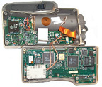
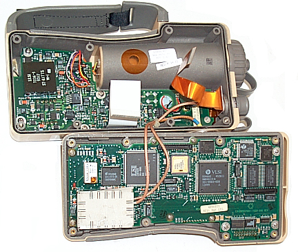
Oxidized ribbon cables
There are two ribbon cables going from the front panel to the
rear printed circuit board. The white ribbon fits into a
socket on both ends and the dark orange ribbon cable fits into a
socket on the front panel PCB.
The display was erratic and after a random time the display
would change to some pattern or it would break up into
gibberish. The receiver would not run for more than
about 10 minutes without display problems.
By using a small philips screw driver to remove the 6 screws
on the back and slightly separating the front panel from the
back-box you can access the ribbon cables. They can be
removed from the sockets by raising the socket clamp bar about
1/32". Then the ribbon cable can be slid from the
socket. One side of the ribbon cable has metalized
"fingers" that can be cleaned by using a fresh soft pencil
eraser and then cleaning the rubber particles with something
that will not leave any residue. DO NOT USE YOUR FINGERS
TO CLEAN. Clean all 3 ribbon ends.
Pressing Up or Down causes the cursor to move Right
This caused by being in Number Lock mode. To get back into
arrow mode press Num Lock so you see "P" in the lower right
corner of the display.
Manuals
TM 11-5825-291-10-2
TM 11-5825-291-13 Operation & Maintenance
TO 31R4-2PSN11-1, EE174-AA-OMI-/PSN-11, PCN
6000028200
about an inch thick.
TB 11-5825-291-10 operator check list & menu navigation (on
ETM)
TB 11-5825-291-10-2 Soldier's Guide for the PLGR, May
1966. 148+ pages, cartoon style
TB
11-5825-291-10-3 PLGR Made Simple
TB 11-5825-291-30 warranty technical bulletin (on ETM)
This is a 12 channel using the NightHawk signal
processor and Phoenix RF front end.
With the ADK (Azimuth Determination Kit) add on, angles can be
determined to better than 3 mils and with a dual receiver system
to better than 1/2 mil. A mil (1/64000 of a circle) is
about 1 yard at 1,000 yards range.
http://www.rockwellcollins.com/ecat/gs/PLGR-II.html?smenu=104
Other GPS
Models
SAASM - Selective Availability and Anti-Spoof Module
Single chip GPS solution
DAGR - Defense Advanced GPS Receiver
Follow on the PLGR National
Security Space Road Map
First Article
awards Oct 2002
has second PPS frequency, compass and map
GRAM - GPS Receiver Application Module
Standardized military GPS receiver used for embedding into
systems. GRAM is actually a family of products, with varying
physical configurations and functionality. Current planning
calls for a minimum of three configurations VME bus and SEM-E for
avionics applications, and PCMCIA for ground-based vehicle
applications. This form is likely to be the most commonly-used for
Army customers.
SLGR AN/PSN-10 "Slugger" & SAGR
Moved to the Trimble
Trimpack web page.
AN/PSN-8
1980 Manpack, an Army developed 17-pound GPS receiver made by
Rockwell-Colins (ION Museum: Rockwell
Manpack Global Positioning System (GPS) Receiver)
Generalized Development Model (GDM)
1977 Rockwell GPS receiver. 4 rack panels, two operators,
huge power supply. photo at ION
Museum.
Used in Phase I of the GPS development program by the Air Force
Avionics Laboratory (AFAL).
AN/ASN-149 aka R-2400, aka Rcvr UH
AN/GSN-13 high precision survey GPS system
AEGR Army Embedded GPS Receiver
M1A2 Abrams
Aircraft GPS
|
Aircraft
|
Model
|
Description
|
many
|
R-2332 aka RCVR-3A |
Rockewll GPS aircraft
receiver.
|
UH-60A/L
Blackhawk |
AN/ASN-128B |
Doppler GPS Navigation Set (DGNS) |
CH-47D
Chinook |
"
|
"
|
EH-60A
EW UH-60 |
AN/ASN-163 |
Miniaturized Airborne GPS Receiver (MAGR) |
AH-64A/D
Apache |
|
Embedded GPS - Inertial Navigation System (EGI) |
OH-58D
Kiowa Warrior |
"
|
"
|
| OH-58A/C |
|
StandAlone Airborne GPS Receiver (SAGR) |
AH-1F
Cobra gunship |
"
|
"
|
UH-1H/V
Huey utility helicopter |
|
Cargo utility GPS Receiver (CUGR), |
RC-12
fixed wing |
AN/ASN-149 |
|
Crypto Keys
Common GPS key types are:
Group Unique Variable (GUV) good for one year
Crypto Variable Weekly (CVW) good for 6 weeks
Can be loaded by the
KYK-13, KOI-18 or AN/CYZ-10.
When the AN/CYZ-10 is used the menu choices are:
Radio/COMSEC/LD/TEK/(GPS model#)/QUIT note the key is loaded
as soon as the PLGR is connected to the loader.
"Check GUV Issue Number" - is the error message when the key
expires.
Links
Army Product
Manager - Global Positioning System - Pathfinder
Magazine - PLGR Made
Simple -
2 May 2000: SA
TURNED OFF -
PS Magazine - All
About PLGR Batteries -
External
Protection Module - spike protection on the data lines,
reverse polarity on the external power lines and built in serial
self test.
Integrated
Test System - B -
SUBJECT:
AVIATION SAFETY ACTION MESSAGE (ASAM)
4. SUMMARY OF PROBLEM -
A. THE GLOBAL POSITIONING SYSTEM (GPS)
JOINT PROGRAM OFFICE (JPO) HAS REPORTED THAT C-17, VH-60, AND
HH-60 AIRCREWS HAVE REPORTED ERRORS WITH THE NAVIGATION SOLUTION
IN THE RECEIVER 3A. THE FAILURE MANIFESTS ITSELF AS A
GRADUAL NAVIGATION POSITION SOLUTION RUN-OFF (AS GREAT AS 20-40
NM) WITH NO WARNING TO THE OPERATOR. THE RECEIVER WILL
CONTINUE TO INDICATE A FIGURE OF MERIT (FOM) OF 1 DURING THE
RUN-OFF. THIS OCCURRED DURING THE FIRST MISSION AFTER
CRYPTO KEYS WERE LOADED TO ACTIVATE THE RECEIVER'S SELECTIVE
AVAILABILITY/ANTI SPOOF (SA/AS) FEATURES. ALTHOUGH THE
REPORTED ANOMALIES HAVE OCCURRED WITH THE RECEIVER 3A, THE
FAILURE MODE IS COMMON TO OTHER RECEIVERS INCLUDING THE 3S, UH,
OH, C4, AND MANPACK RECEIVERS USED IN THE V1, V2, AND V3
CONFIGURATIONS OF AN/ASN-149 GPS SETS. THE PROBLEM IS
CAUSED BY CORRUPTED DATA IN THE RECEIVER AND CAN OCCUR WHEN THE
RECEIVER BECOMES AUTHORIZED TO OPERATE IN ENCRYPTED (P(Y)CODE)
MODE. AUTHORIZATION OCCURS WHEN A PREVIOUSLY-LOADED GUV OR
CVW KEY IS VERIFIED BY THE RECEIVER. GUV KEYED RECEIVERS
RE-VERIFY THEIR KEY EACH ZULU DAY. CVW KEYED RECEIVERS ARE
VERIFIED FOR THE DURATION OF THE CVW KEY.
AVIACONVERSIA GPS
Jammer
Army PLGR web page -
PLGR
Notes -
Performance
Testing
of
the
Rockwell
PLGR+
96
P/Y
Code
GPS
receiver
-
MOTOROLA,
INC., Plaintiff-Appellant, v. The UNITED STATES,
Defendant-Appellee. This is an interesting
case where Motorola sued the U.S. claiming that they were not
treated in a fair manner, since after burning a lot of
Motorola's time and money during the specification stage the
U.S. required a sample unit of a commercially available GPS
receiver as part of it's bid package thereby eliminating
Motorola from the bidding.
Back to Brooke's Products
for
Sale, Navigation, PRC-25, Military
Information, Home page
This is the [an error occurred while processing this directive] time
this page has been accessed since since 16 Feb 2003.


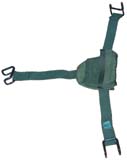 The bag label reads: NSN 5975-01-375-1301,
CAGE 13499, p/n 013-1928-010, Helmet Antenna Mount, 1
each, F04701-93-D-0001 0015 03/95 Under the
flap is: 82820 ASSY SA-?????
The bag label reads: NSN 5975-01-375-1301,
CAGE 13499, p/n 013-1928-010, Helmet Antenna Mount, 1
each, F04701-93-D-0001 0015 03/95 Under the
flap is: 82820 ASSY SA-?????