PP-8249 SINCGARS Battery Charger
© Brooke Clarke 2005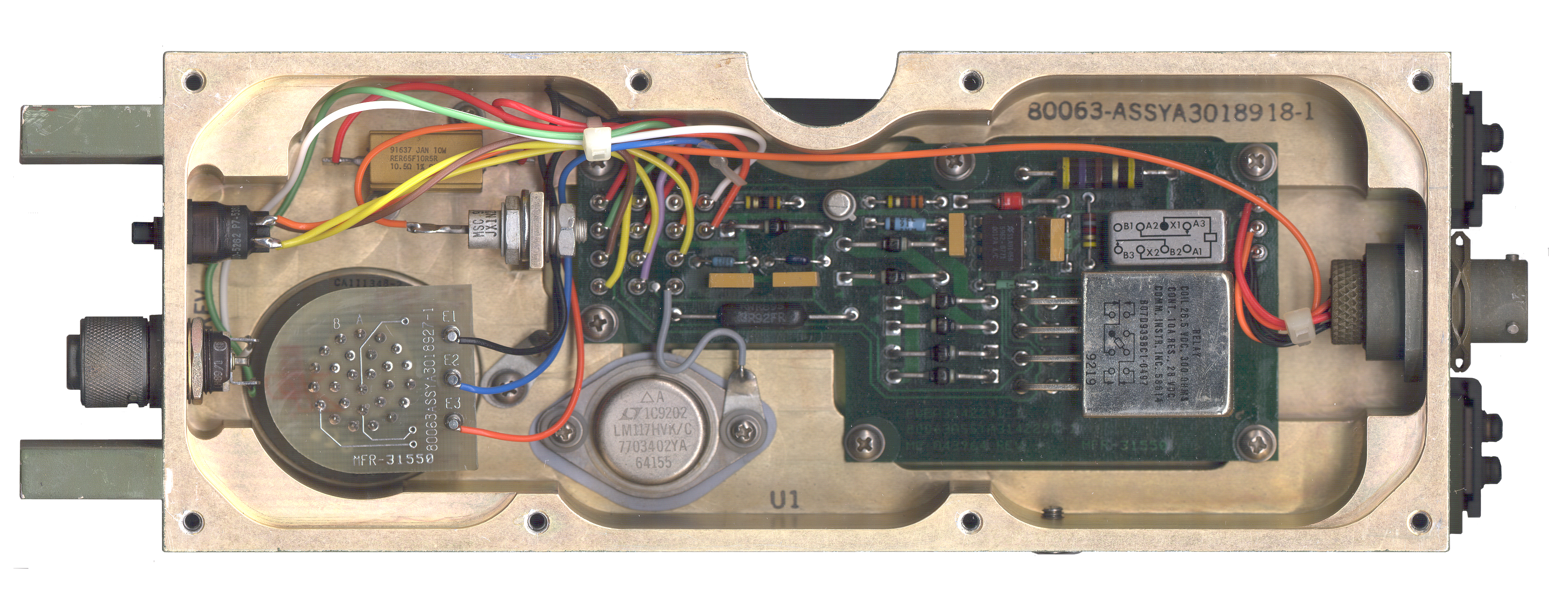 |
|
 |
| Inside |
w/ CY-8523()
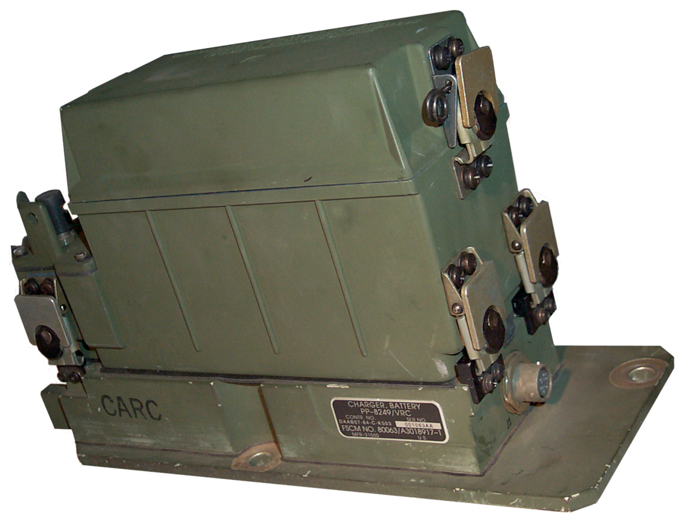
Batt Box Connector end |
w/ CY-8523()
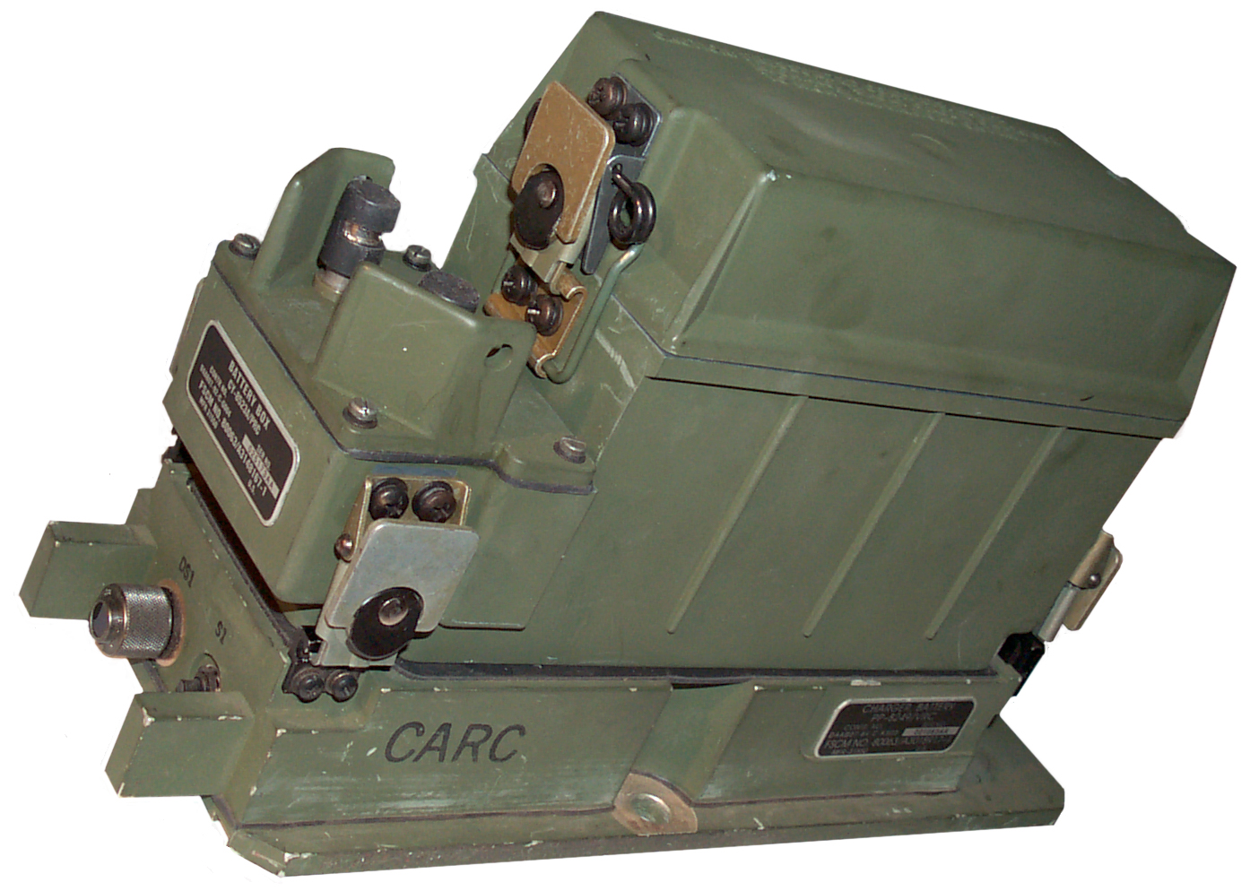
Batt Box push button sw & lamp end |
Background
Unknown. If you have any
information on this battery charger please
let me know.
TM 11-5820-890-30-4 (Chapter 14) shows a "Battery Tray" CY-8664/VRC (NSN 6160-01-339-7723) that's described as a way to use the CY-8523() as a backup power source in a vehicular installation, but not as a charger. When the button is pressed if the lamp lights then the battery has power and if not it should be changed. Aimed at use with a BA-5590 and has the charging function disabled. Used in conjunctin with the MX-10862/VRC Power Supply Adapter.
TM 11-5820-890-30-4 Fold Out 26 CY-8664 schematic has many common features with the PP-8249. The parts layout drawing in TM 11-5820-890-30-5 Fig 15-6 looks identical to the PP-8249. The connector pinout is:
- A & D = Ground to MX-10862 J4 pins A & E.
- F= +27 from vehicle supply by means of CX-13290 cable to MX-10862 J4 Power Supply adapter pin F
- E = Un Interputable + 13 VDC from "Battery Tray" thrugh CX-13290 to MX-10862 J4 pin D
S1 & DS1 Battery Check
The battery test lamp should light when
vehicle power is present and the battery is good. Since DS1 uses
a 28 volt bulb it will not light without vehicle power, i.e. it will
not light with just a good battery.
Description
Label:
Charger, Battery
PP-8249/VRC
Contr No DAAB07-84-C-K503
Ser No 001063AA
FSCM 80063/A3018917-1
MFR-31550
U.S.
Inside there's an LM117 adjustable voltage regulator that the data sheet shows can be used as a battery charger where the voltage and output impedance can be independently controlled thus allowing you to set the initial current and float voltage for a battery. It's a DC charger.
Input Connector
- A = Ground
- F = Red wire
- E = Orange wire (also has a 15 V 10 Watt Zeener in parallel
Charging Function
Although there appeared to be a blue
wire going from the system connector PCB terminal E2 to the main PCB,
it had the other end shrink wrapped and was hidden in a bundle of
wires. After connecting the blue wire to E9 on the PCB (no wire
was on E9 and it's correct from the schematic) then with a discharged
battery installed the voltage across the 3R9 resistor was measured to
be 1.247 Volts (the reference voltage of the LM117 used as a CV-CC
power supply for battery charging). 1.247 V / 3.9 Ohms is 319 ma,
but the power supply was delivering about 500 ma at 30 Volts.
With the BB-390 removed the current is about 80 ma, so about 420 ma of
charging current is being supplied.
Without a battery, but with the blue wire grounded the output of the Battery Charger is 15.64 Volts and the supply current is 500 ma. Diode VR1 is a high power Zeener and it draws charging current when no BB- type battery is installed and the blue wire isjumpered to ground (fooling the charger into operating when it normally would not so the output voltage can be checked, but that voltage is just the zener voltage at half an amp (15.59 V)
By changing the 3R9 resistor to maybe 10 Ohms the charging current would be reduced to a value (<C/10) that could be continuously applied to a BB-390 or BB-590 battery without overheating it. BUT THIS HAS NOT YET BEEN TESTED.
What Goes Wrong
After getting an MX-10862 Power
Supply/Adapter for the RT-1439 SINCGARS
radio but before the Mount arrived I thought that I could power the
radio through the MX-10862 by using the PP-8249 and a CX-13290 cable,
but no joy. After trouble shooting the PP-8249 a burned PCB trace
was repaired using a jumper. But still no joy. Footnote 1
on TM 11-5820-890-30-5 FO-21 says that in order for the CY-8664 battery
tray to supply power from the battery the vehicle input voltage must be
between 2.0 and 32 volts. Note is does not say zero volts.
This is confirmed by the schematic, there's no way either the CY-8664
or PP-8249 will work without at least 2 volts vehicle supply on the
input.
The K1 power relay coil PCB trace to ground was smoked. This can be checked with an Ohm meter reading between pins A and F on J1. Should be under 300 Ohms but measured in the Meg Ohms. Checking the actual relay coil terminals showed that the relay was OK.
The K1 power relay coil PCB trace to ground was smoked. This can be checked with an Ohm meter reading between pins A and F on J1. Should be under 300 Ohms but measured in the Meg Ohms. Checking the actual relay coil terminals showed that the relay was OK.
Back to Brooke's Products for Sale, Batteries, Military Information, Home
This is the [an error occurred while processing this directive] time this page has been accessed since since 10 May 2005.