PTS Frequency Synthesizers
© Brooke Clarke 2012 - 2022
This was purchased on eBay for a very
reasonable price. It turns out because it has no output.
I've heard from another PTS 160 owner that the internal 10 MHz
oscillator may not be working and using an external oscillator may
fix it.
The power supply has outputs of +5
(5.367) and -12 (-12.39).

Uses the comb output of the SGA module and generates outputs
of: 14, 16, 33, 112 and 113 MHz. The outputs of the SGA
and SGB modules supply the reference frequencies used by most of
the outer modules.
The Digit Module is used for all the decades starting from 100
kHz and down to the lowest step size. The lowest step size
module is the first in the chain and is fed by the 14.0000000
MHz reference. It has an output of 14.n00000. Where
n is the value between 0 and 10 of the switch or remote input
for that decade. The next highest DM module has an input
of 14.x0 and an output of 14.nx where n is the input control
data.
This is always the 1 Mhz decade. It works like the DM
module but has an output that's in the 140 to 150 MHz range. It
feeds the Intermediate Mixer (IM) module.
The Step Oscillator contains a VCO that tunes in 10 MHz steps
over a range of 160 MHz (100 & 10 Mhz dials). It feeds
two mixers. One of the mixer outputs is passed through a
505 MHz narrow band filter (black box in photos with tuning lock
nuts) to the IM module. The IM module combines the 505 MHz
signal and the 140 to 150 variable frequency from the DMA module
to generate a signal in the range of 355 to 365 MHz which is fed
back into the other mixer in the SO module generating an output
of 0.1 to 160 MHz. This signal is fed to the Output
Amplifier (OA) module.
The Output Amplifier module contains a filter power amplifier
(+13 dBm max) and a variable attenuator.
| Fig 1 Front Panel |
Fig 2 Top Inside A1 is the Output Amp (OA) A1 is the Output Amp (OA)A2 is the Intermediate Mixer (IM) module A3 is the Step Oscillator (SO) module 100 MHz is really the SGA 10 MHz is really the SGB 1 MHz is the DMA 100 kHz and 10 kHz are DM modules More DM modules could be added to get finer frequency steps. |
Fig 4 Rear Panel |
Fig 3 Bottom Inside |
Fig 4 SGA PCB The problem is with the xtal oscillator. It's powered by the -12.4 DC rail and when the voltage is between 12.5 and 14 there's an oscillation around 500 kHz, far from the expected 10 Mhz. Maybe the McCoy crystal is bad. Need to check my parts bin. ------------------------- The McCoy 10 MHz crystal in the Crystal Activity Meter shows good operation at 10.00 MHz. 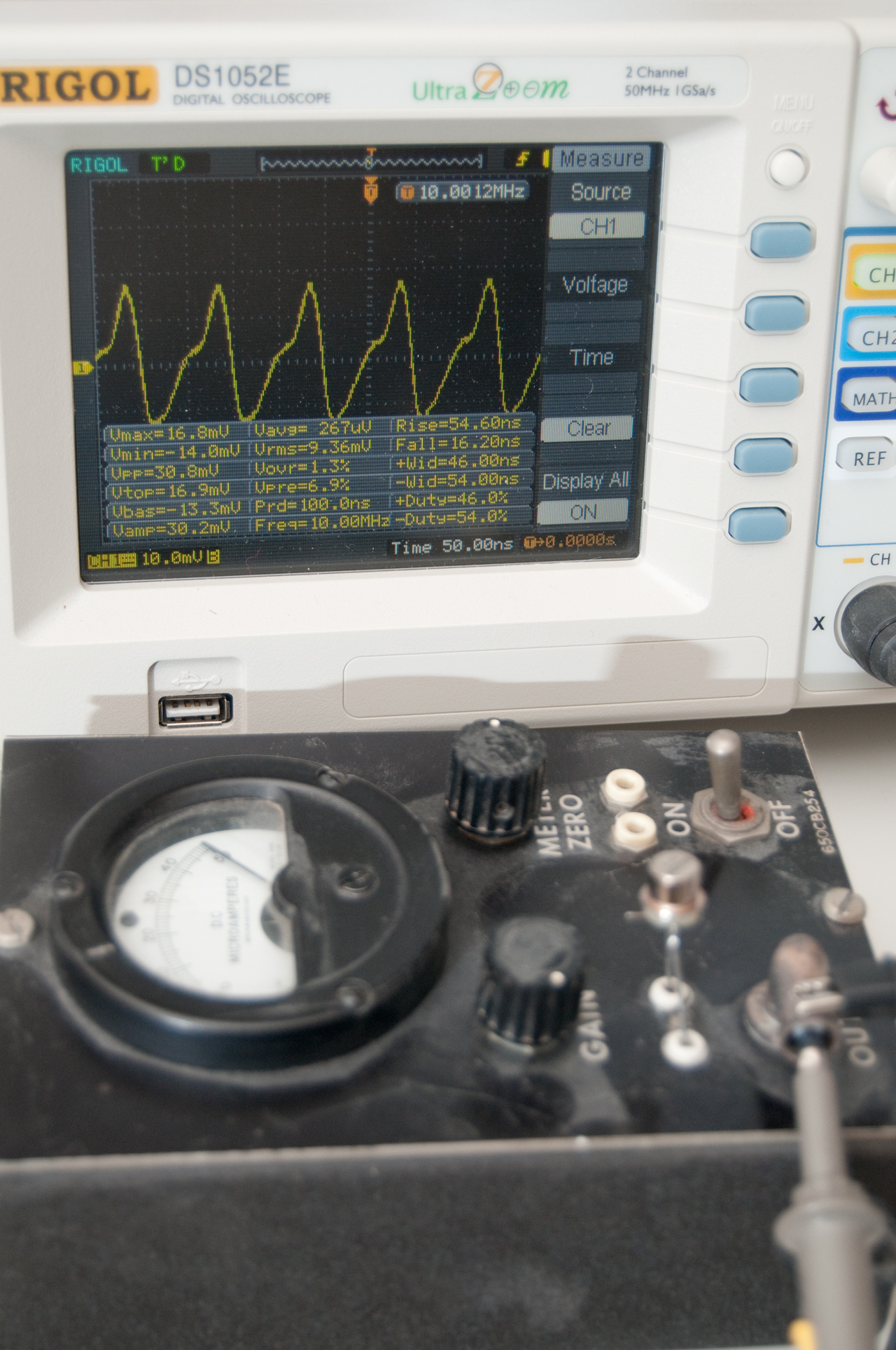 |
Fig 5 SGA schematic (the 10
MHz oscillator part) Q5 and Q4 are the comb generator who's output is at the junction of R22, R23 & R24. Q6 is a buffer amp for the 10 MHz output. Q7 is the 10 Mz oscillator and acts as a doubler if the input is 5 MHz. |
The digits after PTS are the upper
frequency limit in MHz, so the model number PTS 160 S2N1X has an
upper frequency limit of 160 MHz.
The first letter after the upper
frequency digits describes the method of setting the frequency,
the output location and cabinet style.
| Letter |
Control |
Output |
Cabinet |
| M |
Switch
& Rem |
Front |
Rack |
| S |
Switch & Rem | Rear |
Rack |
| D |
Keyboard/LCD
& Rem |
Front |
Rack |
| R |
Remote
only |
Rear |
Rack |
| B |
Switch & Rem | Front |
Bench |
| U |
Switch & Rem | Rear |
Bench |
| V |
Remote only | Rear |
Bench |
| Code |
|
| 0 |
na |
| 1 |
100 kHz |
| 2 |
20 kHz |
| 3 |
1 kHz |
| 4 |
100 Hz |
| 5 |
10 Hz |
| 6 |
1 Hz |
| 7 |
0.1 Hz |
| H |
DDS 0.1 Hz |
| J |
DDS 1 Hz |
| K |
DDS 0.1 Hz |
| 8 |
na |
| 9 |
na |
| Code |
Type |
/day |
/year |
| O |
OCXO |
3E-9 |
1E-6 |
| T |
TCXO |
1E-8 |
2E-6 |
| N |
None |
||
Frequency can be anywhere between 50
and 400 Hz.
| Digit |
Voltage |
| 1 |
120 |
| 2 |
120/220 |
| 3 |
120/240 |
| 4 |
na |
| 5 |
120/100 |
| Code |
|
| A |
Prog
Atten |
| C |
Comb
output |
| D |
1 MHz
input |
| E |
Extra 10
MHz outpts |
| F |
Filtered
Comb or Int Aux Freq |
| FM |
Filtered
Comb & Dual 10 Mhz out |
| G |
GPIB |
| L |
Delta
Output |
| M |
Dual 10
MHz out |
| O |
No
Options |
| P |
90 deg
Phase shifter |
| Y |
Phase
Rotation |
| Rack
Slides |
|
| X-6 |
Rack
handles removed |
| X-8 |
DDS-TLU
over-range |
| X-26 |
DDS load
strobe |
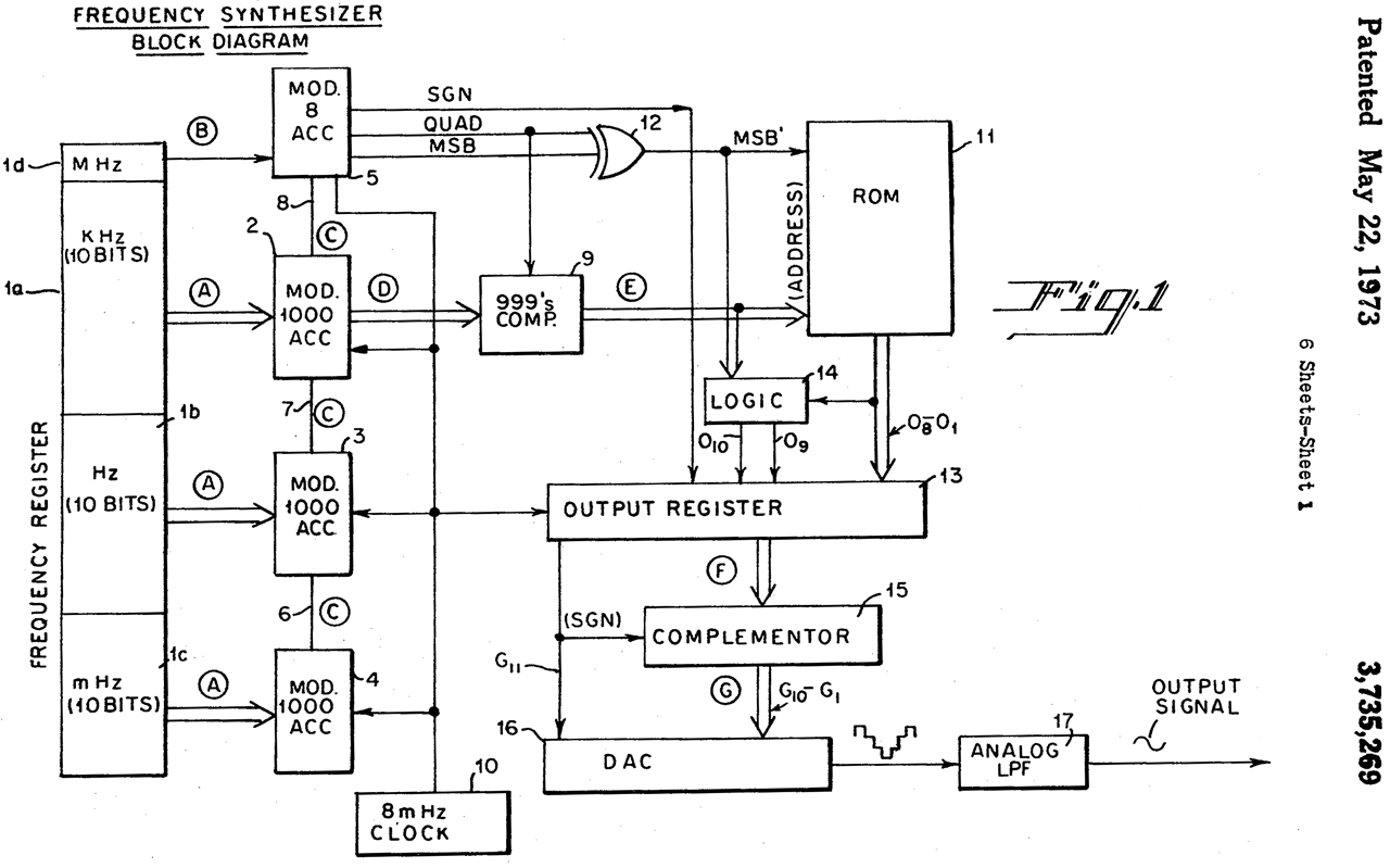
3735269 Digital frequency synthesizer, Leland B. Jackson, Rockland Systems, 1973-05-22, -
Time and Frequency
5110A Synthesizer Driver & 5100A Frequency Synthesizer
HP 8648A Signal Generator
Crystal Activity Meter
Crystal Unit Equivalent Circuit
Crystal Impedance (CI) Meters
Crystals
Time & Frequency Test Equipment
Back to Brooke's Products for Sale, Test Equipment, Microwave Test Equipment, Military Information, Electronics, Personal Home page
page created 4 July 2012.