RC-292 Antenna

NSN 5985-00-497-8554
© Brooke Clarke 2004

RC-292 Antenna drawing
Background
    MP-68 Base
    AB-21, AB-22, AB-23 & AB-24 Antenna Elements & MS-116 - MS-119
        Table of AB- and MS- Elements
        Table of VHF Low Band Radios
        Table of Combinations of elements
Operation
    VHF Low Band Ant Height above local ground
Documents
Inverter Power Supply for PRC-8, PRC-9 & PRC-10
Links

Background

The RC-292 is a VHF Low Band 1/4 wave vertical antenna with ground plane.  RC stands for Radio Component and this antenna was the successor to the RC-291.

The vertical and ground plane elements are made up of AB-21 series elements in the stock configuration or could also use MS-116 series screw together antenna elements.  The antenna only covers a small percentage bandwidth so different numbers of elements are needed to match a given frequency in the 30 to 88 MHz range used by Squad Radios.  Because of this bandwidth limitation the RC-292 can not be used with frequency hopping radios, like the SINCGARS, and so the OE-254 was developed.

This antenna is very reliable and has low loss when the correct number of elements are used for the desired frequency of operation.  Getting the RC-292 on top of a 30 foot mast adds a great deal of range when compared to a vehicle mounted antenna, like the AS-1729.

The OE-254 uses the MS-116 series antenna elements which have the same mating threads as the AB-21 series elements used on the stock RC-292.  These have copper as the exposed metal and when joined the copper oxidizes locking the elements together.  The male threads should be polished and a light coat of Radio Shack Lube Gel applied prior to assembly.

The RC-292 came out about the time of the PRC-8, PRC-9 and PRC-10 radios.  The three different element configurations of the RC-292 match the coverage of the three radios. 

Although mostly used for VHF low band it can be used as an HF antenna by using as many vertical antenna elements are you're comfortable with and adding wires to act as the counterpoise.

Table of VHF Low Band Radios
Radio
Frequency
MHz
No of Vert
Elements/
Length
Vert
Elements
No. of ea. Gnd
radial*/
Length
Gnd
Elements
Opt
MHz°
PRC-8
RT-66
20 - 27.9
6
120"
3 ea. AB-21 +
1 ea. AB-22, -23, -24

6
120"
3 ea. AB-21 +
1 ea. AB-22, -23, -24

31
PRC-9
RT-67
27 - 38.9
4
80"
AB-21, -22, -23, -24


5
100"
2 ea. AB-21 +
1 ea. AB-22, -23, -24

40
PRC-10
RC-68
36 - 54.9
3
60"
AB-21, -22, -23

4
80"
AB-21, -22, -23, -24

54
RT-246
RT-524
PRC-25
PRC-68 Fam
PRC-77
RT-246
RT-524
PRC-6725(LB)
30.0 - 36.5
4
80"
AB-21, -22, -23, -24 5
100"
2 ea. AB-21 +
1 ea. AB-22, -23, -24

36.5 - 50.5
3
60"
AB-22, -23, -24 4
80"
AB-21, -22, -23, -24
50.5 - 75.95
2
40"
AB-22, -24 3
60"
AB-22, -23, -24
* multiply by 3 for the total number of elements
° Frequency of best match as determined by David Fiedler and are recommended operational frequencies to get the best performance out of the RC-292 in it's 3 stock configurations.  Other frequencies might be had by mixing and matching AB-2x and MS-11x elements, see below.

26 June 2004 - The AB-2x series of elements are 27" long whereas the MS-11x series are 1 meter long, otherwise they are interchangeable.

MP-68 Base

MP-68
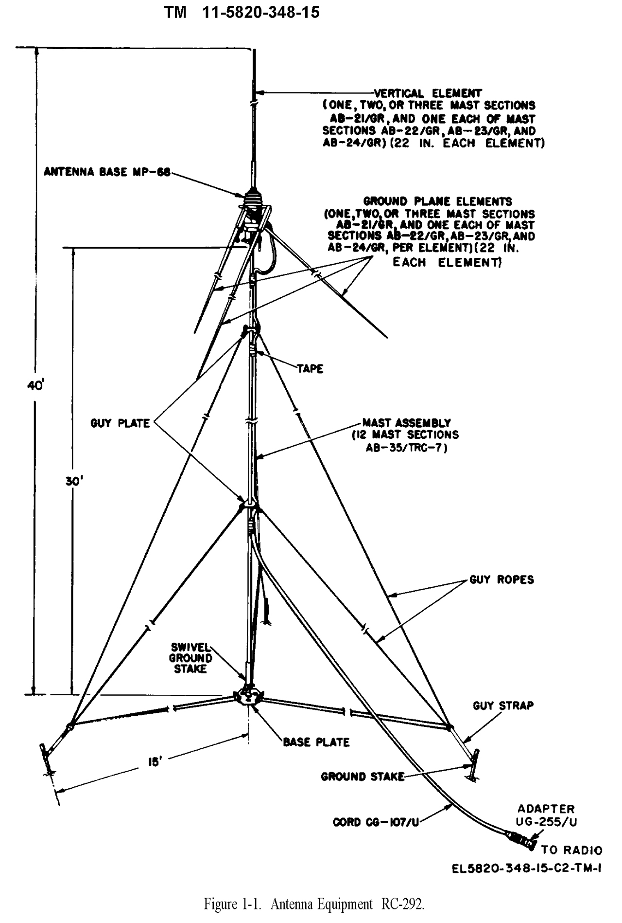
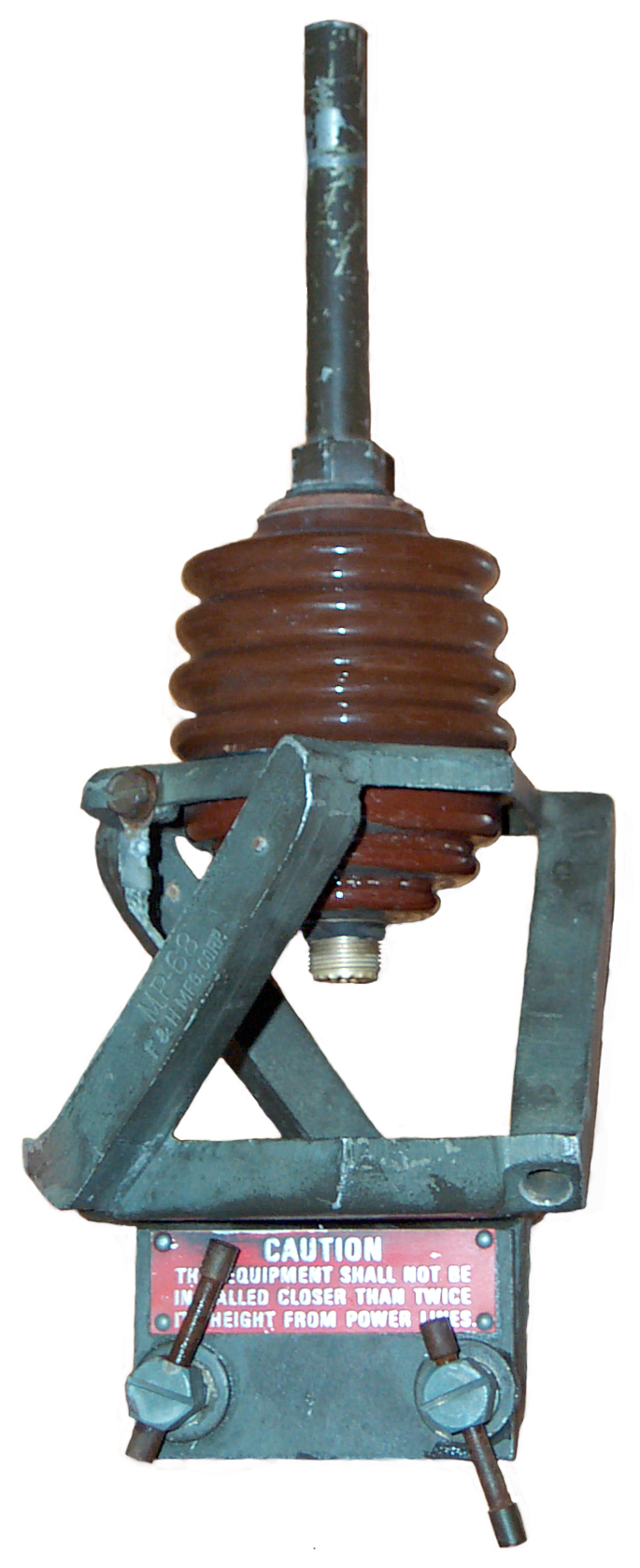
The MP-68 is the heart of the RC-292 antenna.  It holds the insulator, vertical and ground plane elements and has a clamp to attach to a 1.6" diameter mast. 

There is an SO-239 UHF type socket pointing down at the bottom of the insulator.  Since there is not a hole directly below this connector a UHF right angle adapter is needed to get the coax cable clear of the MP-68.

Since it accepts the MS-116 antenna elements, it will also accept the MX-10618 NVIS Antenna base used with the AS-2259 HF Antenna.

The insulator, antenna element female connection, coax connector and ground strap is called the AB-15 antenna base, so the MP-68 is the combination of this standard AB-15 Antenna Base and a metal part that also holds the 3 down sloping ground radials.

AB-21, AB-22, AB-23 & AB-24 Antenna Elements (and MS-116 to MS-119)

Note that the male threads and associated bare copper, about 3.5" long goes inside either the base or another antenna element, so for calculating the electrical length of some combination of elements you need to use the electrical length, not the overall length.
AB-21 Element is 23.5" over all length, 20" remains after screwing into another antenna element or a base such as the AB-15 or MP-68.
AB-21
MS-116-A for comparison.  39.625" (1 meter) O.A. length, 36.25" remain after screwing into another antenna element or a base such as the AB-15 or MP-6.
MS-116-A

Table of AB- and MS- Elements

male O.D.
female I.D.
Name
O.A. Len
El Len
               
Name O.A. Len El Len
0.337"
0.340"
AB-21 23.5"
20"
MS-116
39.625" 36.25"
0.335
0.220'
AB-22 23.5" 20" MS-117
39.625" 36.25"
0.215"
0.220
AB-23 23.5" 20" MS-118
39.625" 36.25"
0.215
ball
AB-24 23.5" 20" MS-119
39.625" 36.25"

In an antenna made up of these elements there can only be one tip section (AB-24 or MS-119) and there can only be one reducing section (AB-22 or MS-117).  There can be a number of the base sections (AB-21 or MS-116) or a number of the smaller diameter sections (AB-23 or MS-118). 

For some reason most configurations only make use of a single AB-23 section, but the antenna may have better wind survival if a second AB-23 was used instead of the AB-21.  The resulting antenna would have lower wind resistance and be more flexible.

The MS-116 series elements can be used with the AB-21 elements to provide a much wider variation in electrical lengths.

The AB-24 can be stored inside the AB-21 just as the MS-118 can be stored inside the MS-116.  Doing this both saves space and protects the thinnest of the elements.

Table of Combinations of elements might be:

Length"
# AB
# MS
Opt Freq
based on Vert len
MHz = 3216 / in.
20
1
0
160
36.25
0
1
88.7
40
2
0
80.4
56.25
1
1
57.2
60
3
0
53.6 (54 MHZ*)
72.5
0
2
44.4
76.25
2
1
42.2
80
4
0
40.2 (40 MHz*)
92.5
1
2
34.8
96.25
3
1
33.4
100
5
0
32.2
108.75
0
3
29.6
112.5
2
2
28.6
116.25
4
1
27.7
120
6
0
26.8 (31 MHZ*)
128.75
1
3
25.0
132.5
3
2
24.3
136.25 5 1 23.6
140
7
0
23.0
145
0
4
22.2
148.75
2
3
21.6
152.5
4
2
21.0
156.25
6
1
20.6
160
8
0
20.1
165
1
4
19.5

* The 3 frequencies shown are where the VSWR of a stock RC-292 is optimum according to Proper use of the RC-292 antenna and are different from the classical ham radio (MHz =234/feet) calcualtions, probably becasue of the skew of the counterpoise elements of the RC-292.  For the two cases where the stock RC-292 uses counterpoise element lengths that are longer than the vertical length the equation is close to:
Optimum Frequency = 267 / feet = 3216 / inches.  ideally the counterpoise element length should be a few percent longer than the vertical, but can be the same length.

There may be some practical maximum number of elements or maximum length so not every combination is possible.
It may be that 3 different lengths of counterpoise elements may imoprove the bandwidth of the single vertical element.

Operation

VHF Low Band Ant Height above local ground

The primary purpose of this antenna is to imporve the range of VHF Low Band communications. 
Ant 1
Ant 2
Range
AT-271
radio on ground
Ant up
AT-271
radio in backpack
Ant up
2.7 miles
AT-271
radio in backpack
Ant up
AT-271
radio in backpack
Ant up
5.4 miles
RC-292
RC-292
36 miles

Note that the range depends on line of sight much more than it does on RF power levels.

Documents

Technical Manuals

TM 11-5820-348-15  Organizational, Direct Support, General Support and Depot Maintenance Manual, Antenna Equipment, RC-292 (NSN 5985-00-497-8554)  Changes  through 7.  23 May 1966.

TM 11-5820-348-24P Repair Parts for RC-292

TM 11-5020

TM 11-612 for the PRC-8, PRC-9 and PRC-10 has some RC-292 information.  The drawing showing the RC-292 which includes the mast and guys has "TM 612-214" in the image.

Field Manuals

FM 24-18 -Tactical Single Channel Radio Communications Techniques - Chapter 3  Antennas -
FM 24-24 - Signal Data References: Signal Equipment - Section 3 Aux Radio Equip -

Training

IS 1132 - MQS II Shared Tasks Antenna Systems Subcourse IS1132

PS Magazine

# 545 April 1998 - Be Recptive to Safety

Inverter Power Supply for PRC-8, PRC-9 & PRC-10

Inverter Power Supply
      for PRC-8, PRC-9 & PRC-10This supply uses a 6 Volt Gell Cell battery to replace the BA-279/U.
It's made by Pietro in Italy.

More in Mil batteries on the TS-183 page.
also see: PRC-10 Maintenance/Ops Section 2 -


Links

RC-292 and OE-254 characteristics, problems -
Marines adopt new broadband very-high-frequency antenna for combat-net radios -- should the Army follow suit? - COM21 may replace both RC-292 and OE-254, but it's not clear to me if the COM21 can be mast mounted.  This is vital since the main benefit of the RC-292 or OE-254 is the elevation gained from mast mounting.
Proper use of the RC-292 antenna - use the 3 minimum VSWR frequencies for best efficiency  (or choose element length to match frequency)

Back to Brooke's PRC68Products for Sale, Military Information, Antennas, Personal Home

[an error occurred while processing this directive] page created 14 June 2004.