
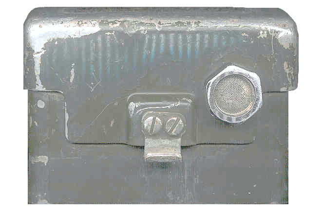
Front Top Bottom Back Open BA-5598/U LiSO2
NOT FOR USE ON
PRC-25!BA-4386/U Mag. Safety Vent on
Battery BoxPressure test plug
in center
This is a man pack VHF Low Band squad radio covering 30.00 to 75.95 MHz in 50 kHz steps. It uses wide band FM modulation. Even the more modern Low Band VHF radios that tune in 25 kHz steps use wide band FM because it supports encryption systems that preserve the speakers voice. Commercial VHF radios use 5 kHz channel spacing and what's called narrow band FM modulation.
Vehicle versions are AN/VRC-53, AN/VRC-64, AN/GRG-125, AN/GRC-160 TM 11-5820-498-12, -20P, -34P, -35
AN/VRC-12 series TM 11-5820-101-12
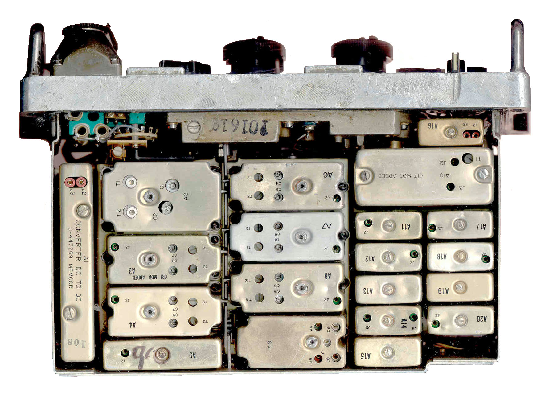
A pair of these PRC-25 radios came from eBay where the seller described them as "These units have most likely seen the battlefield with all the scars on them. Very rugged and sturdy. " and although they have seen a lot of use, they turned on and are working fine. Most electronic equipment that had received the abuse that these units have had would be non functional (i.e. destroyed).The RT-505/PRC-25 is constructed using discrete components (no ICs). Instead of being built on a single printed circuit board there are a number of modules, each providing a specific function and typically have a small number of connections for inputs, outputs and power. The synthesizer uses a number of crystals and consists of a number of modules, but does not use an IC like the PRC-68.
The German SEM-35 is a similar man pack radio covering 26.00 to 69.95 MHz. It uses the older H-33 handset with the U-77 type AUDIO connector, not the current U-229 type audio accessories.
This radio was one of, if not the first to use the 150 Hz tone to open the squelch. It turns out this was a mistake since an enemy can "Squelch Capture" the radio and prevent it from receiving.
The first battery used in the PRC-25 was the BA-386/PRC-25. Note the "PRC-25" suffix. Most military batteries have a "/U" suffix indicating they have Universal application. I think this means that the PRC-25 and it's battery were designed at the same time. Later the BA-4386/PRC-25 battery replaced the earlier one. The BA-4386/PRC-25 battery was made in very large quantities and so became a standard battery for many other military items.
The PRC-25 was replaced by the PRC-77 late in the Vietnam era. The form, fit and function of the PRC-77 are backwards compatible with the PRC-25 and, except for the label the two radios are identical from an outside visual inspection.
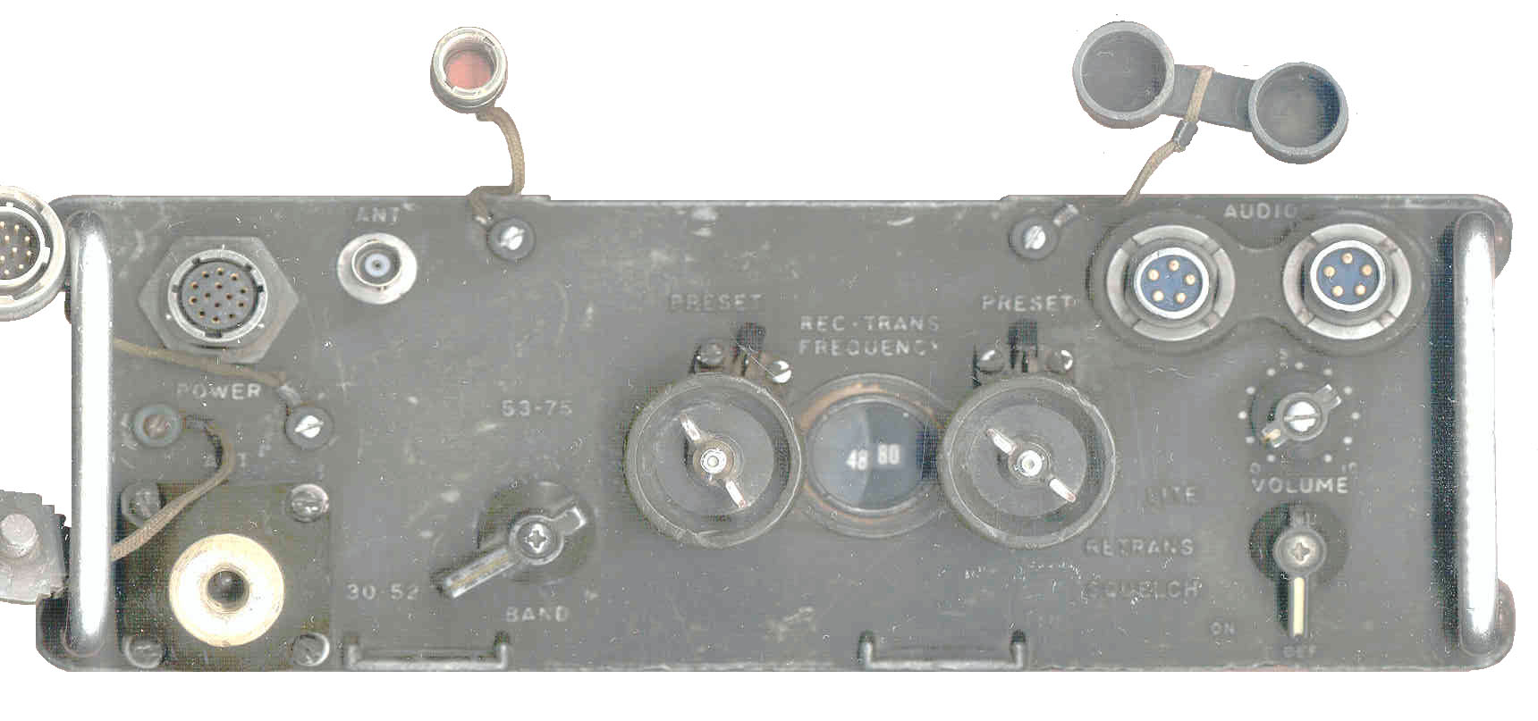
The method of selecting frequency uses two knobs, one for integer MHz and the other for the 50 kHz steps. This is very similar to the RT-68 (jpg) all tube radio.
Specifications
There is a summary of test data in paragraph 67 of TM 11-5820-398-35.
Module block diagram on page 110 of TM 11-5820-398-12.pdf (this is current through change # 6)
A Check List for testing an RT-505/PRC-25 by using a known good radio.DC Power
The PRC-25 uses a simple classic form of battery power where the battery is connected directly to the circuits using the power, there are no switching type supplies here. If the load presented to the battery looked like a resistor then the power delivered (audio or RF) will be proportional to the battery voltage squared. For the normal "12 volt" voltage range of 10 to 15 volts the power ratio is about 1 to 2.25 watts.
PRC-25 & PRC-77 Batteries
2577BA Battery Adapter
Need 3 and 15 Volts
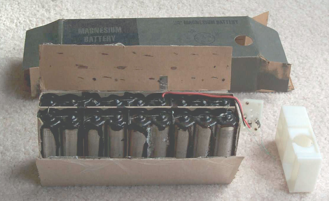
BA-386/PRC-25 Carbon cell Dry battery
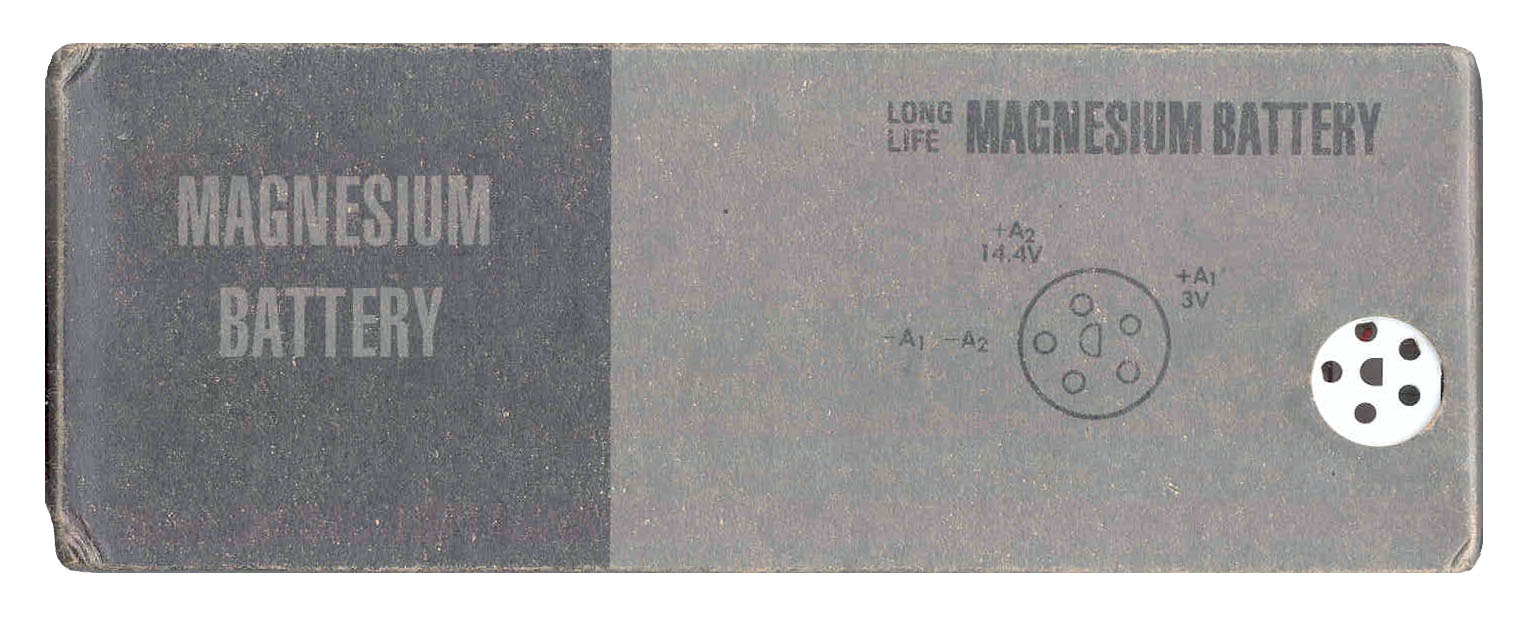
BA-4386/U Magnesium cell with twice the capacity as the BA-386 NSN 6135-00-926-8322WARNING - This battery out gasses Hydrogen gas as a normal part of its chemistry.BA-898/U (-398/U?) for Arctic operation (17 hours of operation) NSN 175-00-926-3503
It MUST be used with a battery box that has the vent! If an unvented battery box is used,
when the latches are released the box may shoot off of the radio and cause personal injury. Mike Murphy experienced this in person. Also the Hydrogen gas may explode.
I heard from a Marine MOS 2841 Ground Radio Repairman who installed the vents. He said that this was done for the PRC-77 radios since the PRC-25s had been removed from service by the time the problem was known. The install kit included:
In addition there would be some number of the vent plugs.
- a Template and instructions
- a pilot drill bit
- a hold punch
- tube of Silicon seal
I'm trying to confirm exactly what this fix was supposed to accomplish.
Caution - I got one of these on eBay that was new in the sealed plastic wrap with an expiration date of 07/99. When tested on 27 Nov. 2001 using a PRC-25 is was about or really dead.
See the first part of the Power Out vs. DC Supply Voltages table below. Buyer beware.Inside there are 18 cells (each about 1.75 Volts) about 0.85" dia x 3.3" tall. There are two groups of three cells in parallel (1.5 V) and these are in series (3.5 V) for the filament. For the +14 Volts there are six groups of two cells (1.75 V) in series (10.5 v) and these are connected on top of (in series with) the filament cells (10.5 + 3.5 = 14 V). The wires from the battery to the connector for the ground and +14 are about 18 gauge BUT the for the filament it is #30 wire wrap wire and is about 5" long. This is either to add resistance and/or act as a fuse? It measures 1.28 Ohms resistance, so it may be a current limiting resistor for when the final tube has a cold filament.
BA-5598/U 1/2 size Lithium primary batteryCX-8088/G Special Cable Assembly connects the battery-vest to the radio Warning - CECOM has a no use bulletin for the BA-5598/U in the PRC-25. They have a very large inrush current and may explode because of over current. (So far I have not been able to find this, there is however a PS magazine article saying the BA-5598 is Taboo for the PRC-25 probably because of the lack of current limiting on the 3 Volt supply.)BB-586/U NiCad rechargableCurrent Consumption
Note:
When the Function switch is in the OFF position the +15 Volt section of the battery sees an open circuit, BUT the 3 Volt section is loaded with about 40 k Ohms 75 micro Amps. This is probably small enough to ignore except for long term storage when the battery should be removed form the radio.
On & quiet On & full noise Transmit LITE 15 Volts 50 mA 47 mA 1,100 mA 0 3 Volts 0 0 375 mA 255 mA The filament has a hot resistance of 2.77/.375 = 7.38 Ohms.
The LITE tests only the 3V part of the battery, and this is commonly the part that discharges first in a field application.
24 hours of standby (On & quiet) would require a 1.2 AH battery.
If there was a 1 minute transmission every hour for 24 hours then a 3.0 AH battery would be need.
A 3.02 AH battery would last for 2 hours of talking and no listening.
The common Alkaline "C" battery has 8.35 AH and a "D" battery has 18 AH of capacity.
A good NMH rechargeable "D" cell might hold 8 AH.Power Out vs. DC Supply Voltages
3 V 15 V 51.0 MHz
Pout (W)3 V Cur
Amp12 V Cur
AmpBA-4386 BK1786 3.0 15.0 2.0 ? 1.08 3.0 14.0 1.8 ? .98 3.0 13.0 1.5 ? .90 3.0 12.0 1.3 ? .81 3.0 11.5 1.4 ? .83 3.0 11.0 1.2 ? .78 3.0 10.5 1.2 ? .76 3.0 10.0 1.1 ? .72 3.0 9.5 1.0 ? .67 3.0 9.0 0.9 ? 0.62 3.0 8.5 0.8 ? 0.58 3.0 8.0 0 ? 0.36 E3631A BK1786 3.0 15.0 2.3 0.346 1.13 2.5 15.0 2.0 0.308 1.09 2.0 15.0 1.5 0.269 0.95 1.5 15.0 1 0.226 0.8 Note: Using a "new" BA-4386 battery from eBay for the 15 Volt supply produced only 1.0 Watts,
checking the voltage across the Magnesium battery showed :
14.8 V on receive with noise heard, but
9.97 Volts on Tx after 10 seconds of PTT.
Maybe these "new" batteries are not such a good deal!
After replacing the BA-4386 as the 3.0 V supply the power out increased from 2.0 to 2.3 Watts,
so it looks like it's filiment section was also a little weak.
As a confirmation the BA-4386 was connected directly to the PRC-25 and the power output checked.
The result was 1.0 Watt.Also tried a BA-5598/U Lithium 1/2 size battery that was purchased as New Old Stock. The power out of the PRC-25 with this battery was 1.4 watts, almost a watt lower than it should be, but better than the NOS BA-4386/U. WARNING - This was a mistake, the BA-5598/U is too hot for the filament and can damage the final tube, see below.
TS-183 Battery Test Set results on the same batteries as tested above
BA-5598/U A1 Jack 6
>2.7 V2.65 V BA-5598/U A2 Jack 12
> 14.0 V14.0 V BA-4386/U A1 Jack 6
>2.7 V3.18 V BA-4386/U A2 Jack 12
>12.0 V15.0 These results seem to say that the BA-4386/U meets all specs and is better than the BA-5598/U, but functional testing on the radio says the BA-5598/U performs better than the BA-4386/U and also that the BA-4386/U is about dead. This points out the difficulty in testing modern battery chemistries with the TS-183 method of lightly loading the battery and measuring the loaded voltage. That's why testers like the LS 91 were developed.
Since the voltmeter range is coupled to the jack number, you cannot use a lower load resistor than the minimum one for the same color jack.
In the case of Yellow Jack 12 for the 15 V section the lowest resistance Yellow jack is number 11 at 100 Ohms that gives about the same results as jack 12 at 298 Ohms.The PSM-13 Battery test set showed the BA-4386 completly dead.
Page 35 of 210 in TM 11-5820-398-35 says the transmit frequency should be within +/- 3.5 kHz with the supply voltages set at 2.25 (fil) and 10 (main), indicating that these are operational voltages.
Figure 79.7, standard receiver test setup and Figure 79.8 (paragraph 103) standard transmitter test, of TM 11-5820-398-35 is the setup for the PRC-25 and uses 12.5 Volts for the B supply and 2.5 volts for the A supply as the normal condition. 2.25 & 10 Volts for the low voltage testing and 3 & 15 Volts for the high voltage testing.
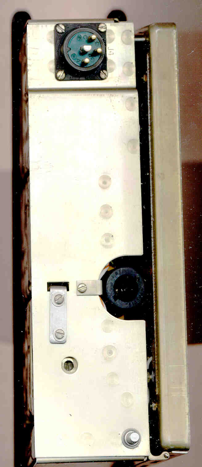
J3 Power Connector Pin Out
Seperate web page about the POWER connector.
POWER pin PRC-25 Function AUDIO pin PRC-77 Function A Ground A same B Rx audio B same C PTT C same D Mic D same E +15 power to FUNCTION switch (Ext + 15 VDC in here) - same F +15 VDC from battery (Z1 jumper plug connects E & F) - same H feed +2.5 VDC to FUNCTION switch LITE position
or to PA final Tube filament
(Z1 jumper plug connects H, L & M)
(Ext +3 VDC in here)- spare, not used
PRC-77 uses a
15 V LITEJ ground for pin D - same K ReTrans PTT E same L +2.5 VDC from battery - gnd = tone disable M +2.5 V to A10 diode bias
(Ext +3 VDC in here)- spare, not used N switched +13 from FUNCTION switch - +10 VDC reg P spare, not used
PRC-25B wideband audio out with PCC-1 Mod- wideband audio out R spare, not used
PRC-25B wideband audio in with PCC-1 Mod- wideband audio in The Z1 (GC U-317/U) jumper plug must be connected for the radio to work from the battery.
If your's is missing I could make a functional equivalent based n the same plug used for the VPA2577 Vehicle Power Adapter cable, but this would just look like the plug with no wires. If interestedlet me know.
External DC Power
- Pin A is ground
- Pin E has the vehicle "12 Volt" power
- Pins H, L & M would need a current limited 2.5 Volts
VPA2577 Vehicle Power Adapter
This is a cable with Power Pole connectors for the "12 Volt" input DC and a connector to mate with the POWER connector on the radio. It has a resistor divider to supply the 3 Volts for the A10 module diode biasing and a series resistor for the LITE test or the final tube filament.
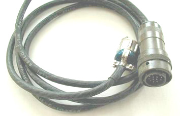
CX-8808 Artic Battery Cable
One end, with a 5 pin plug, connects to a battery that's worn under the radio operator's clothing to keep it warm. The other end has a U-316 plug to mate with the PRC-25 or PRC-77 POWER connector.
Modification For use with AN/PCC-1 multiplexer = PRC-25B
This increases the bandwidth to 0.3 to 20 kHz. May have been used with the TH-81 Multiplexer, Provides one voice orderwire channel, four 100 WPM teletype channels and 4 telephone channels, with companding, Used with AN/VRC-12
and AN/PRC-77. Note that the use of J3 pins P & R was determined by this modification to the PRC-25 and became the standard used on the PRC-77.Modules
# Function ID Mod Alignment -35 parag A1 Converter DC to DC C-447269 Memcor A2 Power Amp Tank 43, 72e A3 First RF Amp CR1 Mod Added 73d,e A4 Second RF Amp " A5 Receiver Mixer 74d,e A6 Transmit Intermediate Power Amp 75d,e A7 Transmit Second RF 76d,e A8 Transmit First RF 77d,e A9 VFO late model
64009-PP-6344, 78c,d A10 Interval Osc (14 each Xtals) C17 Mod Added 79e,f,g A11 Freq Synth Discriminator Divider 80d,e A12 Freq Synth Second Mixer 81e,f A13 53 MHz Filter 82d A14 Freq Synth First Mixer 83e,f A15 1 MHz Spectrum Generator ( 1 MHz Xtal) 84d A16 Voltage Regulator late model na A17 Freq Synth Phase Comparator 86c A18 Freq Synth IF Amp late model 87d A19 Quarter Wave Network 88c A20 Side Step Oscillator PCC-1 45, 89d A21A Receiver IF PCC-1 90d A22 Speech Amp Limiter na A23 Tone Generator late model na A24 Tone Squelch late model A25/55 Receiver Audio Amp PCC-1 A26 Synth mother board A27 Hinged Audio & Control chassis A28 Antenna Loading Network A29 Transmit Power Amp (2DF4) FL3 11.5 MHz Filter PCC-1 Z1 Discriminator Whip Antenna Connector
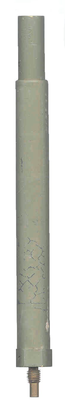
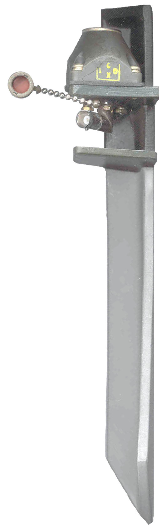
The PRC-25 radio was where the AT-892 3' tape measure whip was developed. This is the same 5/16-24 thread used on most of thePRC-68 family of squad radios. At the bottom of the whip antenna connector on the PRC-25 there is a mechanical switch that changes the antenna tuning for either the AT-892 or when activated by the AB-591 for the 3 meter AT-271.
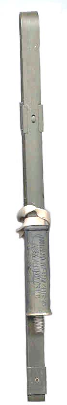
AB-591 Spring
(no flex)
3/8-24 socket
@ top
5/16-24 w/ext
@ botAT-271 Base
3/8-24 baseAT-271 Tip
1/4-28
(3 meters long with 591)AT-892
3' tape
(1 meter long with flex)P/O
AT-892
Spring
+
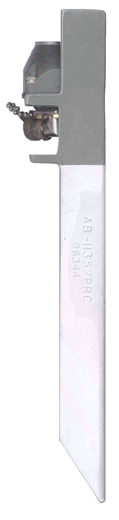
FlexAB-1135/PRC
An angle iron stake that can be driven into the ground and will hold the AB-591 + AT-271 Antenna. The mounting block that accepts the AB-591 looks just like the block on the PRC-25 and has a right angle BNC(f) connector.
These new in government wrap are being sold by Jim Wiliams & Sons Surplus on eBay as "Military Radio PRC-25/77 Antenna Ground Mount". The AT-892 + flex base is about 1 meter long and will be near 50 Ohms at 75 MHz. The AT-271 + AB-591 is about 3 meters long and will be near 50 Ohms at 25 MHz. At other frequencies some type of matching will be needed for transmitting. Maybe the correct length of 75 Ohm TV coax would match the AT-892 and/or AT-271 for use at 51.0 MHz?
4 Sep. 2003 - By opening a joint and folding the top sections down beside the lower sections and tying them together you can make a number of different lengths of whip antenna. Using this method you can easily match the AT-271 to the frequency of operation.
# Sections
Len in.
F Mhz
7
120
25
6
104
28
5
88
33
4
72
41
3
56
53
2
40
74
1
24
123
Transmitter Alignment
Typically the prior stage needs to be removed and the stage being aligned peaked. Can you just aling these using the transmitter itself?
A8 A9 A7 A6 A29 A28 A2 A20 man para 77d,e -35p44 76d,e 75d,e na na -35p43 -35p45 na Tx 1st RF VFO Tx 2nd RF Tx Intermediate Power Amp Tx Power Amp (2DF4) Antenna Loading Network Power Amp Tank side step
osc30 MHz T2 T1 T3 T2 na na T1 T1 & T2
11.5 MHz52.95 MHz C6 na C9 C6 na na C1 na 53 MHz T3 na T2 T3 na na T2 na 64.450 na C9 na na na na na na 75.95 MHz C9 na C6 C8 na na C2 na PS Magazine articles on the PRC-77 and PRC-25
1988 to 1998 Index with links to most articlesA battery of Good Ideas - BA-4386 training, BA-5598 combat. When using the 1/2 size BA-5598/U add center rubber pads 9320-00-930-0724 using cement 8040-00-664-4318. Bat Box should have a vent 4820-00-296-9677.
Item NSN battery support pads 9320-00-930-0724 " " " cement 8040-00-664-4318 Bat Box vent 4820-00-296-9677 The Battery Choice - BA-4386 $13 training, BA-5598 combat $43.
Lithium Battery is Taboo - The reason that the PRC-25 may not work with the BA-5598 is because of the diode inside the battery 3 Volt circuit dropping its voltage below the final tube filament requirement of 2.5 volts. Note that a LiSO2 cell puts out 3.0 volts and has a low internal resistance.
474-42 - Spare Some Care For Radio Set -
Item NSN AUDIO contact cleaner 6850-00-105-3084 AUDIO dumbell cover 5340-00-973-1732 POWER shorting cap 5935-00-973-1859 battery connector gasket 5330-01-049-0038 AT-271 top cap 5999-01-259-5009 4546-45 - PRC-77 Keep nut tight on KY-57 - CX-12991/U cable (NSN 5995-01-058-2513).
486-61 - Clip for CW-503 -
Item NSN ALICE keeper
bag to belt
TM 10-8400-203-235340-00-735-5580 451-42 - LC-2 Frame for PRC-25 or -77 - TM 11-5820-667-12 and -20P are short on NSNs
509-44 - Safe and Secure in LC-2 Frame -
Item NSN LC-2 Pack Frame
w/ straps8465-01-073-8326 Left quick-release strp 8465-00-269-0482 Right quick-rel strap 8465-01-078-9285 Lower Back strap w/clamp 8465-01-151-2891 Waist strap 8465-01-075-8164 Cargo tiedown strap (2 each) 8465-00-001-6477 Extra Shelf for KY-57
TM 11-5810-256-10-28465-00-001-6476 450-44 - PM Tips - tape can be used in place of the dumbell AUDIO cover
Old link = http://www.logsa.army.mil/psma/1990/450/450-44-45.pdf
new link =https://www.logsa.army.mil/WEB-PAGE/1990/450/450-44-45.pdfThe M-80, H-189 and a lot of other AUDIO accessories that use the U-229 connector use this same O-ring.
Item NSN H-250 connector O-Ring 5330-00-905-6032 Never use a lithium battery in an AN/PRC-25's RT-505 receiver-transmitter. This type battery will damage the radio's tube. Only use the magnesium battery. (??WHY?? - Ans. Maybe the BA-5598/U 3V section has no current limiting needs to be checked!!!)
Update - The early BA-5598 batteries had two diodes, one for the 15 Volt sectin and one each for the 3 Volt section to prevent charging. Later when they removed the diode from the 3 Volt section, since no one was going to try and charge it there and because of the problem of low filament voltage and the output increased enough to be a problem for the PRC-25.
2 Sep 2004 A thought. If the 3 volt anti-charging diode was a Silicon PN junction type it would have about 0.6 volts drop resulting in about 2.4 volts to the tube, which may have been on the low side.
25 Nov 2004 - The BA-4386 uses a piece of 5" long #30 wire that has about 1.28 Ohms of resistance to limit current flow in the filament. It seems the designers of the BA-5598 were not aware of this.
520-46 - Whip Antenna Troubles -
Item NSN AT-271 cord 4020-00-281-8439 CLP (4 oz bottle) 9150-01-079-6124 When folding the AT-271, start at the top so that the spring at the base can work. If you start at the base the spring will not be able to work
428-44 Keep the AUDIO contacts clean and shiny
427-23 - Keep the ANT drain hole clear
435-47 - Make your own harness from LC-2 stock parts
Item NSN Frame 8465-01-073-8326 Tiedown (2 each) 8465-00-001-6477 Shelf 8465-00-001-6467
TM 11-5820-398-35 Radio Set,
AN/PRC-25 (Reprinted W/Basic Incl C1-2)TM 11-5820-398-20P Radio Set
AN/PRC-25 (NSN 5820-00-857-0759)
TM 11-5820-398-34P
Radio Set AN/PRC-25 (NSN 5820-00-857-0759)TM 11-5820-497-20P
Direct Support and General Support Maintenance Repair Parts and Special Tools Lists
(Including Depot Maintenance Repair Parts and Special Tools) for
Receiver-Transmitter, Radio, RT-505/PRC-25 (NSN 5820-00-857-0934) April 1979
Note that the VRC-64 and GRC-160 replace the PRC-25 with the PRC-77.
These manuals also have information on the VIC-1 Vehicle Inter Communication system that connects to the MT-1029 holding the AM-2060 Audio Amplifier - Power Supply.
TM 11-5820-498-12 Operator’s and
Organizational Maintenance Manual
Radio Sets
AN/VRC-53 (NSN
5820-00-223-7467),
AN/VRC-64 (NSN
5820-00-223-7475),
AN/GRC-125 (NSN
5820-00-223-7411), and
AN/GRC-160 (NSN
5820-00-223-7473), and
Amplifier-Power Supply Groups
OA-3633/GRC and OA-3633A/GRC
(NSN 5820-00-973-3383)
TM 11-5820-498-20P Organizational
Maintenance Repair Parts and Special Tools List for
Radio Sets
AN/VRC-53 (NSN 5820-00-223-7467),
AN/VRC-64 (NSN 5820-00-223-7475),
AN/GRC-125 (NSN 5820-00-223-7411),
and
AN/GRC-160 (NSN 5820-00-223-7473)
and
Amplifier, Power Supply Groups
0A-3633/GRC and 0A-3633A/GRC
(Parts List for 0A-3633/GRC and 0A-3633A/GRC (NSN
5820-00-973-3383) Only))
TM 11-5820-498-34P Direct Support and
General Support Maintenance Repair Parts and Special Tools
List
(Including Depot Maintenance
Repair Parts and Special Tools) for Radio Sets
AN/VRC-53,
AN/VRC-64,
AN/GRC-125 and
AN/GRC-160 and
Amplifier, Power Supply Groups
0A-3633/GRC and
0A-3633A/GRC (Parts List for OA-3633/GRC and 0A-3633A/GRC,
NSN 5820-00-973-3383, Only)
TM 11-5820-498-35 DS,GS, and Depot Maintenance Manual Radio Sets
AN/VRC-53,
AN/VRC-64,
AN/GRC-125 and
AN/GRC-160 and
Amplifier-Power Supply Groups
OA-3633/GRC and OA-3633A/GRC
TM 11-5820-497-34P
Reveiver-Transmitter, Radio, RT-505/PRC-25 (NSN 5820-00-857TM 11-2300-364-15-1 Instructions for Installing Radio Set AN/VRC-46, AN/VRC-53, or AN/GRC-125, and Intercommunication Set AN/VIC-1(V) Installation Units, in Armored Vehicle Launcher Bridge (M48A2 Hull)
TM 11-2300-362-15-2 Radio Sets, AN/VRC-46, AN/VRC-53 or AN/GRC-125; nstallation Unit in Mobile Floating Assault Bridge/Ferry
TM 11-2300-361-15-4 Installation of Radio Set AN/VRC–12, AN/VRC-46, AN/VRC-47, AN/VRC-53, or AN/GRC–125 and Intercommunication Set AN/VIC–1(V) in Tank, Combat, Full-Tracked, 105MM Gun, M60
SB 11-660 Recoverability Code A for
Modules in AN/VRC-12 Series, AN/TTC-38, AN/PRC-25 AND AN/PRC-77
SB 11-131 List of vehicle instllatoin kits
Standard Equipment PRC-25 Set NSN 5820-00-857-0759 (GRC-125)
RT-505/PRC-25 Receiver Transmitter and RT-505A/PRC-25 NSN 5820-00-857-0934
CY-2562/PRC-25 Battery Box - 13 Sep 1972 MWO 11-5800-211-1 install pressure relief valve NSN 5820-00-086-7148
ST-138/PRC-25 Harness Electrical Equipment NSN 5820-00-892-8094
Batteries BA-4386/PRC-25
CW-503/PRC-25 Cotton Duck Accessory carry bag for both antennas and handset (w/2 ALICE clips) NSN 5820-00-086-7138
- AT-892/PRC-25 spring base & 3' tape measure Whip Antenna NSN 5820-00-889-3893
- AT-271-A 7 section 10' long fishing pole antenna NSN 5820-00-242-4967 - 3/8-24 thread on base & 1/4-28 at tip.
- AB-591/PRC-25 Antenna Support NSN 5820-00-086-7149
- H-138(*)/U Handset TM 11-5965-257-15, or
- H-189/GR TM 11-5965-280-15 NSN 5965-00-069-8886
Optioinal Equipment
MK-456(*)/GRC Retransmission Cable TM 11-5820-101-12, TM 11-5995-202-20PHas no provision for external DC power, but that could be provided though the POWER connector.
- CW-502/PRC Cotton Duck bag
- CX-4656/GRC 50 foot cable with coil box (series RFC on each line) and network box
- spur chart of non compatable frequencies on page 108 & 109 of TM 11-5820-398-12.pdf
MK-456 Cable connects between the AUDIO connectors on two PRC-25 radios.
AN/GRA-39 Remote control TM 11-5820-477-30, -12, -23P and AN/GRA-6
SB-22/PT Manual Switchboard
AM-4148 Range Booster RF Amp
AN/GSA-7, TM 11-5135-15, -15LD, TM 11-5820-274-24P ,O-574/GRC Oscillator 5820-082-4049 for use with AN/GSA-7 for Radio Wire Integration of the PRC-25 asa well as the PRC-8, PRC-9, PRC-10.
- CX-7474/U Cable
AT-784/PRC Homing Antenna TM 11-5985-284-15, TM 11-5985-284-24P
- O-574/GRA Oscillator SB 11-602
- SC-C-75348 Cable Assembly, Oscillator to H-33/U handset
- CX-10177/U Y-Cable Assembly connects to RT-595/PRC-25 and audio accesory like H-189/U
- 4 each BA-1312 Mercury batteries
AT-984/AG 150 foot wire Antenna FSN 5820-926-0201 (may be an early version of the OE-303)
- CG-3344/PRC Cable Asembly, radio to antenna
- CG-2840A/U extension cable
- AT-1082/PRC Loop Antenna
- CW-922/GRC Cap shields the radio whip antenna connector
RC-292 Antenna TM 11-5820-348-15 Is a 1/4 wave whip with 3 sloping ground elements, need to adjust all element lengths for the freq.
OE-254/GRC Antenna Group TM 11-5985-357-13 Is a broad band 1/2 Rhombic
the MT-1029 vehicle mount goes with the AM-2060. Drawing of just the AM-2060 & power cable CX- ,
For more on the cabling between these see TM 11 5820-498-12 Fig 2-3. & TM 11-5820-401-35-9
AT-912/VRC An earlier version of the AS-1729.
MT-3823 Shock Mount - holds the PRC-25 directly, no electrical parts, or the KY-38 when used with the PRC-77
LC-2 ALICE pack frame and two cargo starps
AM-1780 Vehicle Audio amplifier and related VIC-x equipment: C-2296, C-2297, C-2298
AS-1729 Antenna -
PSM-13 Battery Test Set
. PSN-6 LORAN-C Receiver that attaches where the battery box normally goes. The top of the PSN-6 has a recess to hold the radio battery and the standard CY-2562/PRC-25 Battery Box holds a second battery for the PSN-6. The PSN-6 uses the AT-892 1 meter tape antenna and it's flex base. Although the Loran receiver attaches to the radio there is no provision for automatic position reporting, the radio operator just uses the H-250 handset to report his position or that of a target.
The dual rubber cover for the two AUDIO connectors is NSN: 5340-00-973-1732 p/n: SM-B-447220
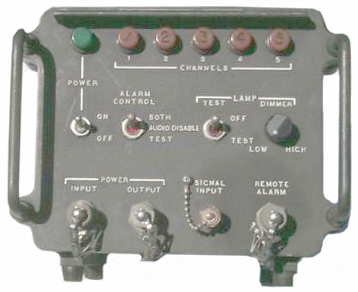
KY-671 Decoder Indicator
This is now a mystery so if you actually know about it please let me know.
The name "Decoder Indicator" says this box was ment to receive a signal that has already been encoded and this box decodes the signal and then lights one of the channel indicator lamps and activates an alarm. It can not do the encoding, so having a pair of these does not make a working system.
On the front panel there are:
This unit was designed to work with the PRC-25 and so probably uses audio tones in the voice frequency range. The PRC-77 has a much wider IF bandwidth to support digital voice encryption. The Signal Input connector is a BNC-f not an audio type connector that would be expected for audio tones from the PRC-25. So this is a mystery. Maybe the Signal Input will take a signal direct from an antenna or . . . .? ? ?
- Power on-off switch
- Green power on lamp
- 5 lamps marked Channel 1 through 5
- Alarm Control with selection of Both, Audio Disable or Test
- Lamp Test On -Off
- Lamp Dimmer Low to High
- Power Input 3 pin mil connector
- Power Output 3 pin mil connector
- Signal input BNC-F (this is strange)
- Remote Alarm 3 pin mil connector.
28 June 2006 - This may be related to the GRA-114 which is a system that locates enemy artillary by time of arrival of the "boom". This equipment works in the VHF low band. The Outdoor Instusion Detectors work in the VHF Hi band and do not interoperate with the PRC-25.
AM-4306 ?
AM-4477 Range Booster optionally with CY2577 DC Power Supply for use in AM-2060 with MT-1029.
Test Equipment
Field
TS-2609(*)/U AN/URM-182 Power Meter (looking for 0.5 to 3 Watts) uses a short BNC-BNC CG-409/G/U Cable, TM 11-6625-2718-14&P
PSM-13 Battery Tester - Warning - Do NOT test the BA-5598/U, the adapter may burn out because the LiSO2 chemistry can produce much more current than the BA-4386/U Magnesium battery this meter was designed for.
PRM-34 "God Box" small multifunction test set that includes a power meter and field strength meter. This power meter is a two connector through type so you can measure both power to the antenna and the power reflected from antenna and tell if the antenna has a bad VSWR.
Depot
PRC-25 Specific
TS-1755 AN/GRM-55 Test Set, Electronic Plug-In Circuit,TM 11-6625-514-12, TM 11-6625-514-45P, NSN 6625-00-973-2117, includes 150, 1000 kHz and 25 MHz osc. TM 11-6625-514-12 for operation.
3" Module Extender Fair Radio photo
Mk-1745 Test accessories kit - The MK-1745/U Electronic Test Kit is designed to test the AN/PRC-77, AN/PRC-25 Radios, also the AN/PCC-1, AN/TRC-166, AN/MRC-134, AN/MRC-135, and other Tactical Radio and Terminal Sets. It includes a variety of different breakout boxes for multi-pin and 5 pin audio connectors on front panels of radios that allow measurements and testing of the transceivers, as well as, the accessories. Also included are two BIRD Model 80BNCM DC-1 GHZ, 5 watt, 50 Ohm Dummy Loads (DA-318/U), various BNC connector adapters, BNC to Banana plug adapters, a Power Supply Test Load Box, Resisters, Attentuators, Test Leads, Manuals and a fiberglass storage case.
Test Adapter for the POWER connector has push down terminals for 12 of the 14 pins.
Generic
AN/URM-48 Signal Generator TM 11-1257, TM 11-6625-267-35P
AN/URM-25F Signal generator TM 11-5551E, TM 11-6625-278-20P, -40P, TM 11-5551B
ME-57/U Modulation Meter TM 11-6625-400-12, -14&P, -20P, -35, -40P
AN/URM-26 Frequency Meter TM 11-5057
AN/URM-43 RF Watt Meter TM 11-5133
TS-382F/U Audio Oscillator TM 11-6625-261-12
TS-723A/U Spectrum Analyzer TM 11-5097 (this is really an HP 33x series distortion analyzer used for receiver sensivity testing)
ME-26B/U Multimeter TM 11-6625-200-12
ME-30A/U Voltmeter TM 11-6625-320-12
AN/USM-50A Oscilloscope TM 11-5129
PP-2953() - 25.5 VDC power supply for testing MT-1029, AM-2060 etc. , TM 11-6130-233-12, -24P, -35
AN/PRC-25 A Forgotten Legend by Dennis StarksBack to Brooke's Products for Sale, Telephones, PRC-68 Family of Squad Radios, U229 Audio Accesories, Audio Connectors, Military Information, Electronics, Home page
Firsts:
U.S. Military Portable Radios By Alan D. Tasker, WA1NYR with Rebuttal by Dennis Starks
- solid-state radio of it's type
- synthesized radio ever built
- to use 105 Hz tone squelch
- Low Z dynamic mike
- U-229 connector replaced the U-77
- very rugged construction
Navy Advancement - Seabee Combat Handbook - Chapter 11 Organic Communications Equipment -
Steve Haney makes an Audio Amplifier/Power Supply that allows using the PRC-25 in a vehicle and the audio and DC power are through the POWER connector on the radio. He also has some of the accessories.
First Battalion Fourth Marines - Communications – Electronics - after action reports some notes about PRC-10, PRC-25 interopertion and battery usage
The Radio That Got Entire Platoons Killed in Vietnam, 13:09 - AI choose the wrong image in some cases
0:00 The 5-Second Life Expectancy
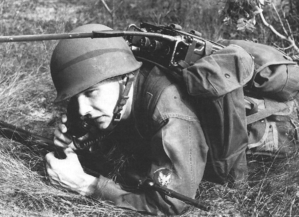
1:15 The AN/PRC-25: A 25-Pound Bullseye
4:00 Priority Target: Why the NVA Hunted RTOs
6:30 The Intercept: Reading American Comms in Perfect English
9:15 Deadly Consequences at LZ Albany and Dak To
11:45 The Fix: SINCGARS and the RTO Legacy
[an error occurred while processing this directive] page created 26 Oct. 2001.


