Thermal Hand Held Imager DFOV
© Brooke Clarke 2015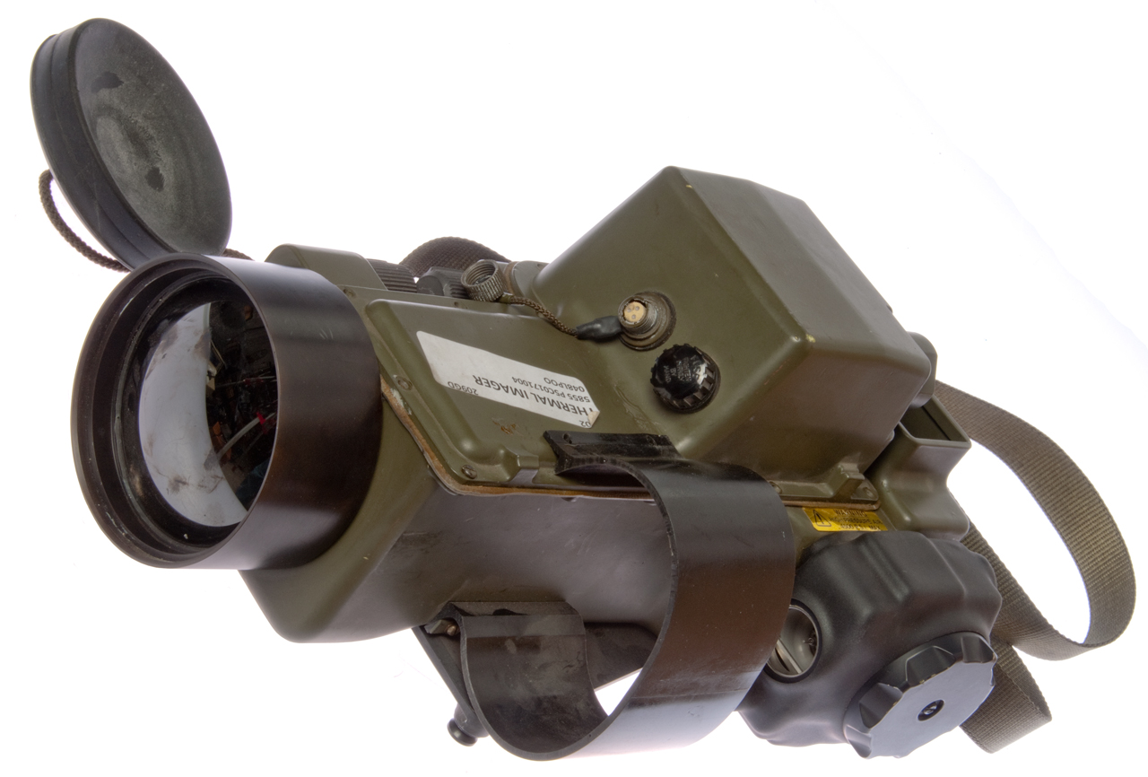
Description
Photos
Patents
Comments
Related
Links
Background
Part of my interest in things optical and IR. Note Wein's Displacement Law (Wiki) relates the peak wavelength emitted from a black body to it's temperature.
Thus the Sun's surface temperature of 5,500 K translates to a peak wavelength of 550 nm (where human eyes are most sensitive). Also a human with a 98.6 def F body temperature has a peak emission at 10 um or 10,000 nm in the far infrared so thermal sensors typically work in a wavelength band centered on 10,000nm.
Description
Made by Thorn EMI labeled:
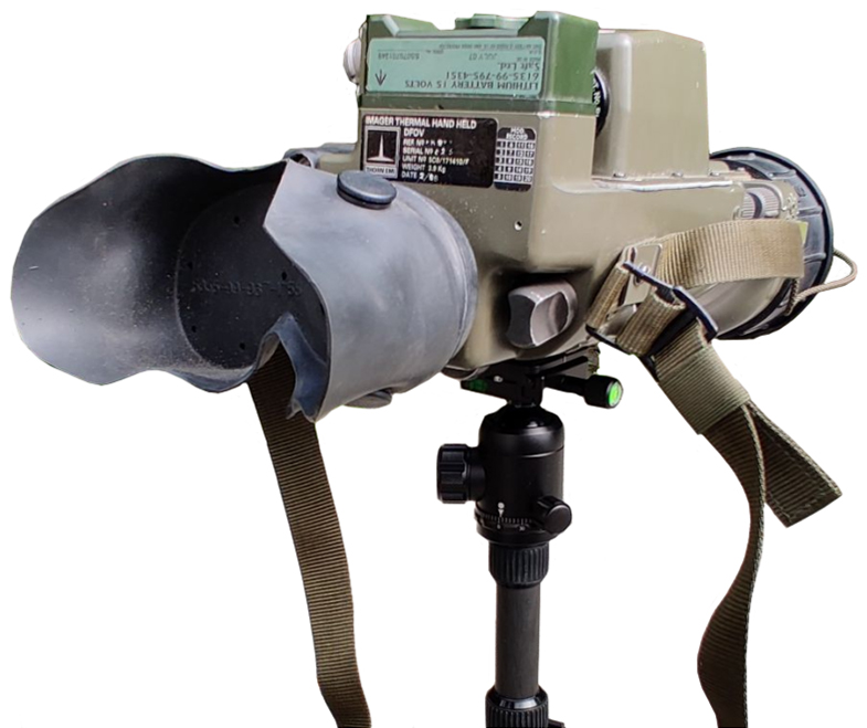
Imager Thermal Hand Held, DFOV (Dual Field of View), Ref: No D0024-5005, Unit No. 5C0/171410/3, Weight 3.9 Kg, Date 8/91.
Mod Record shows 1 & 2 marked.
A green house (Wiki) functions by letting light in but blocking long wavelength IR. So glass blocks far infrared. When a person is wearing glasses in a far IR photo they glasses will look black since they block the heat. So glass lenses can not be used in far infrared optical systems.
The lenses are not glass (you can not see through them) and probably are made from either Germanium (Ge), Chalcogenide glass, Zinc Selenide (ZnSe) or Zinc Sulfide (ZnS). I expect the lens material was chosen pass the wavelengths that the sensor responds to and block other wavelengths to maximize the signal to noise ratio.
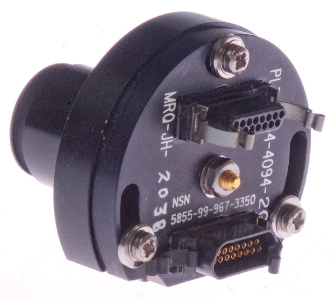
The light output module is marked: NSN 5855-99-967-3350, PL3 Y-34-4094-20 SK2, MR2-JH-2038. It has two micro-D 15-pin connectors, one with male pins and one with female sockets. I think there are two linear arrays of LEDs (Left and Right) inside, so the sensor may have a similar configuration.
The sensor has a micro-D female pin connector with 31 contacts. So the sensor may have a two line configuration.
The mirror drive motor has three wires, red, black and brown, which is DC power an an index mark to synchronize the signal processing. One of the small mirror arms has a small mirror that's sensed as the small mirrors go up and down.
Photos
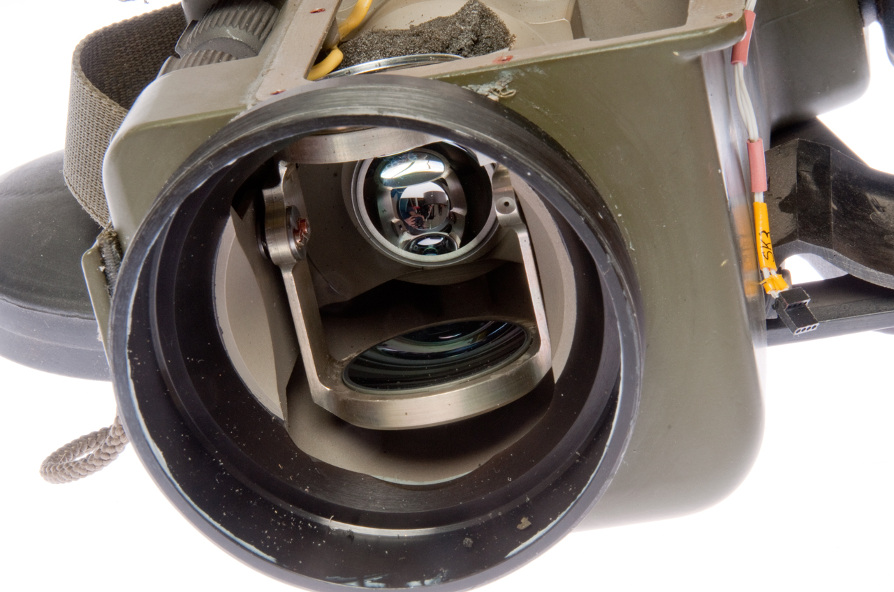
Fig 1 The objective lens is shiny black.
Fig 2 The rubber cup is missing on the eyepiece. Open box is the battery compartment.
Fig 3 Contrast and brightness controls.
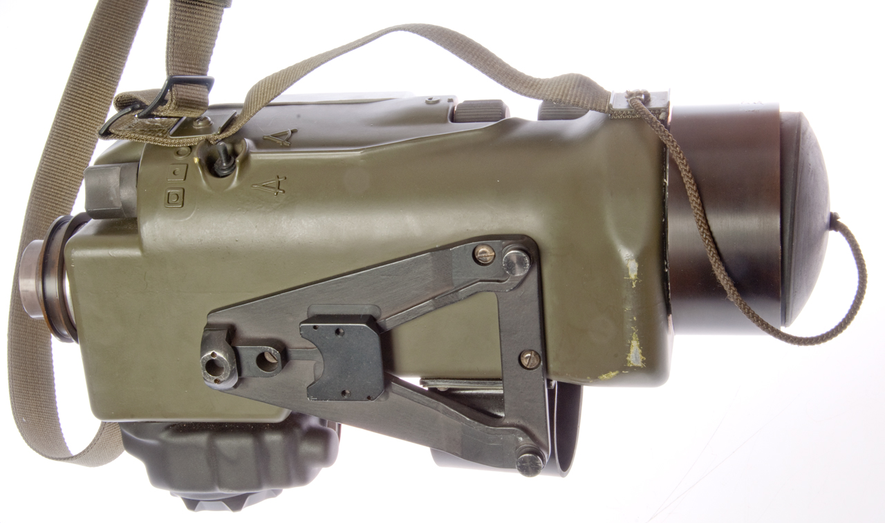
Fig 4 DFOV (Dual Field of View) switch for wide or narrow
Specialized mount for ???
Fig 5 Loop is to hold compressed (air?) bottle for cooling sensor. The large black knob opens the jaws that hold the pressure tank and when closed push in the tank valve releasing the gas.
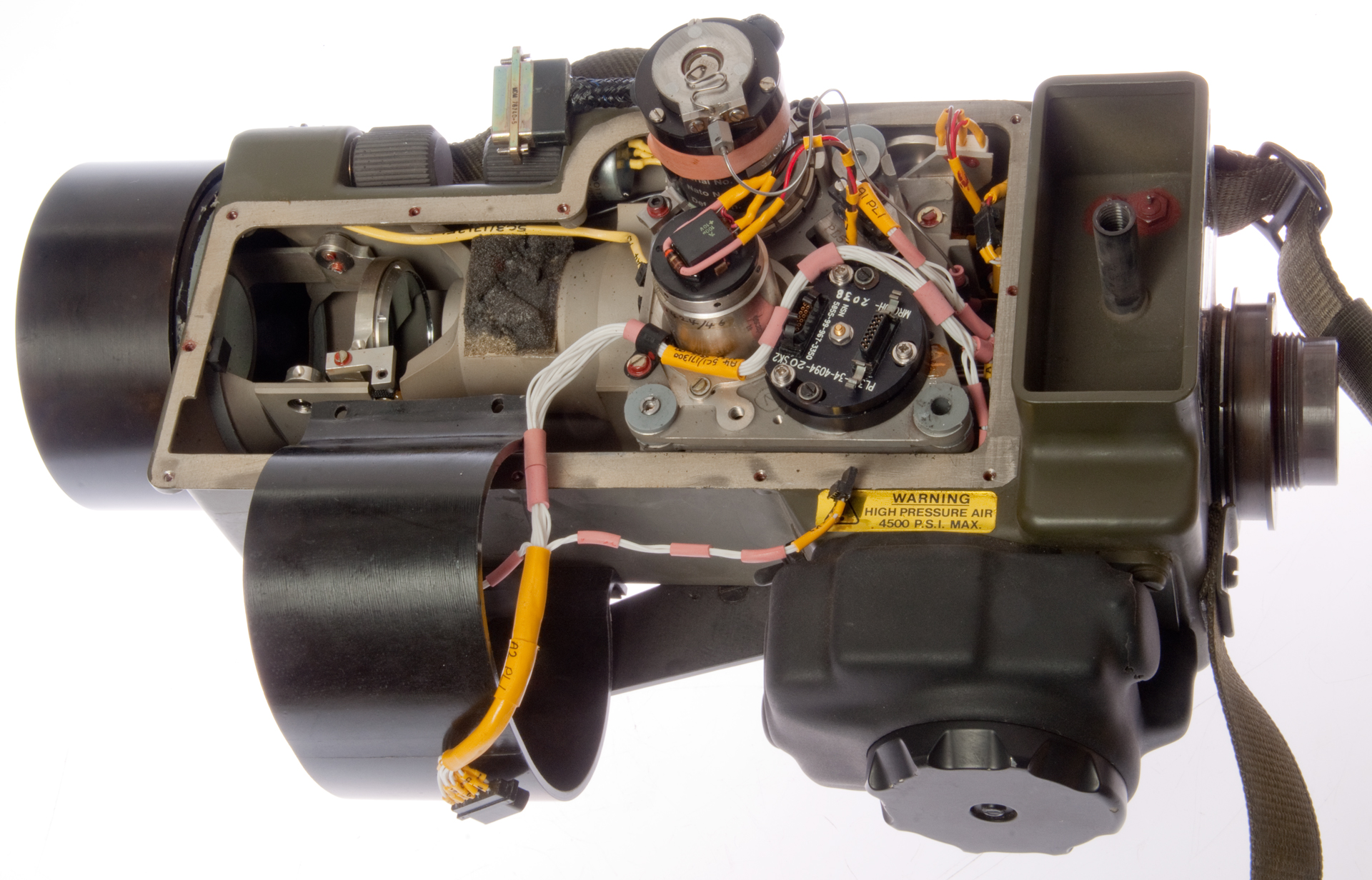
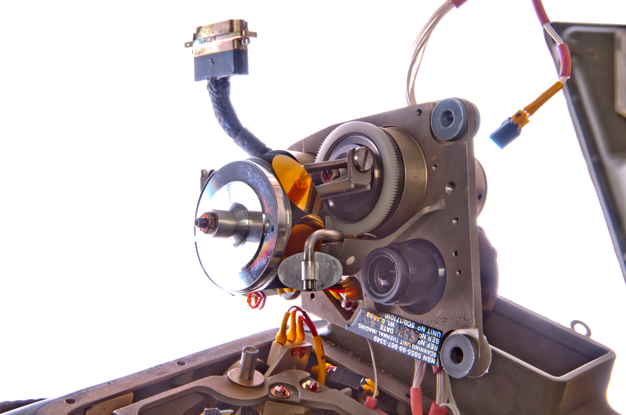
Fig 6 Cover removed
Cooled sensor tall cylinder at upper left of scanning plate
6-sided mirror motor below sensor
output light source to right of motor
Note the output light path is offset from the input path.
The input centerline matches the sensor scanning mirror
the output centerline matches the light source scanning mirror
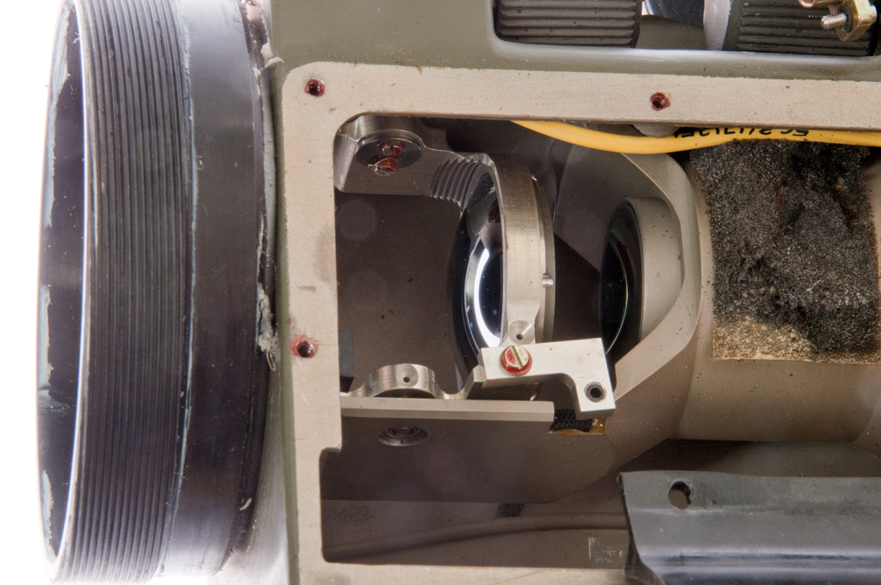
Fig 7 Optics shown in narrow view mode
Cooled sensor at upper left and mirror motor to it's right.
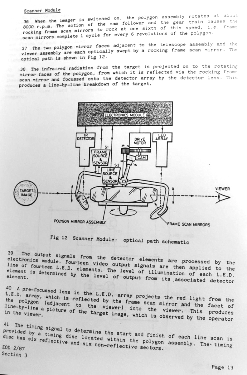
Fig 8 Optics shown in narrow view mode.
Fig 9 Optics shown in wide view mode.
Fig 10 In wide view mode the magnification lenses are out of path.
Fig 11 Inside cover external power input and fuze.
Fig 12 Cover by itself.
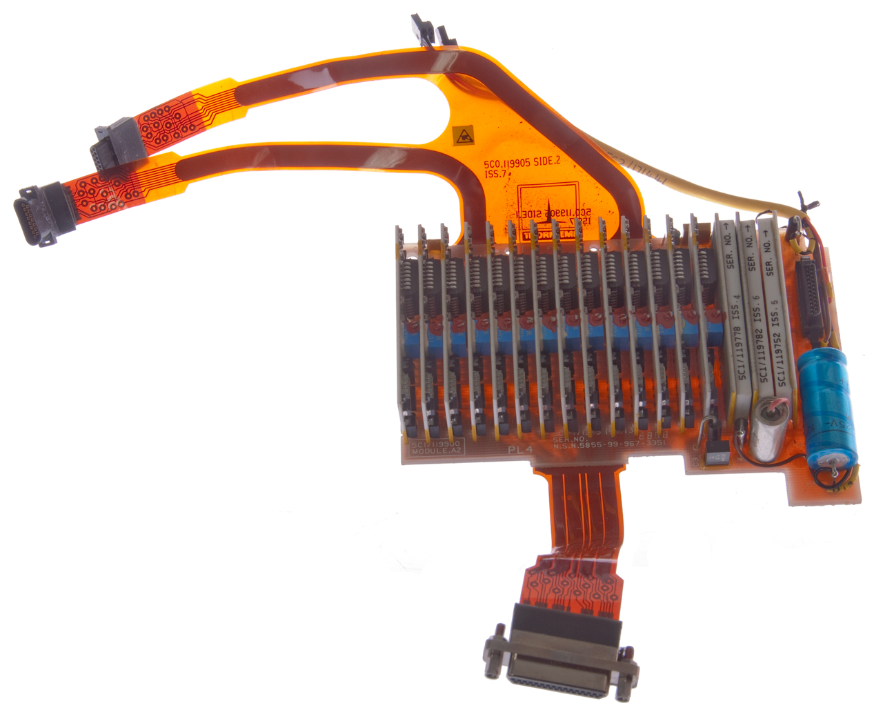
Fig 13 Electronics board has 14 daughter boards, maybe one for each brightness level.
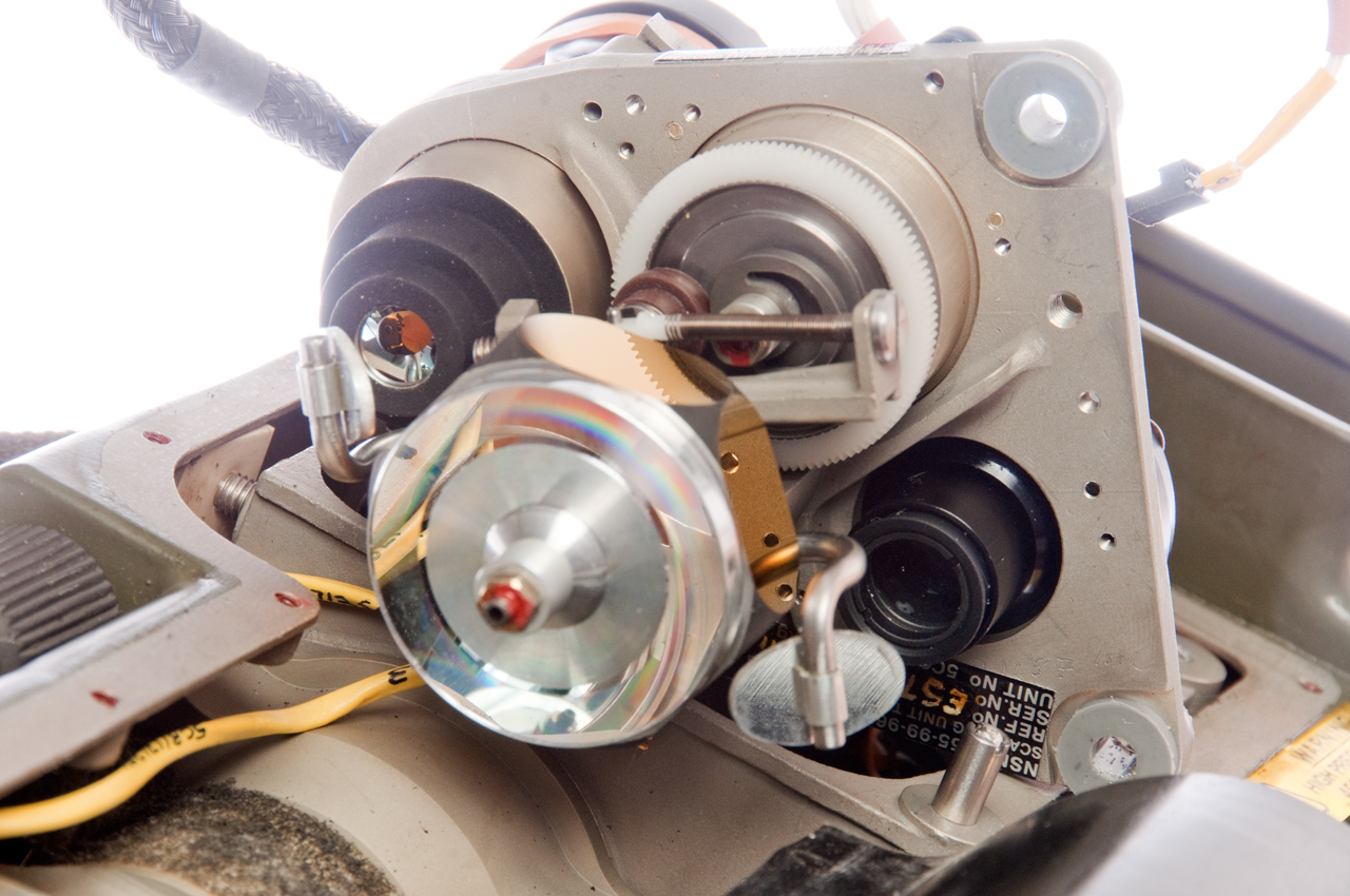
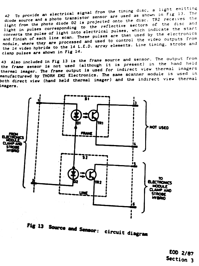
Fig 14 Bottom of scanning plate with 6-sided spinning mirror and two small mirrors for input and output. The small mirrors move up and down while the 6-sided mirror spins
Fig 15 Cooled input sensor at upper left and output light source at lower right.
Fig 16 Video of scanning mirror system
https://youtu.be/2mILFRVP-D4
Fig 17 LED visible light output module.
Two rows (left and right)
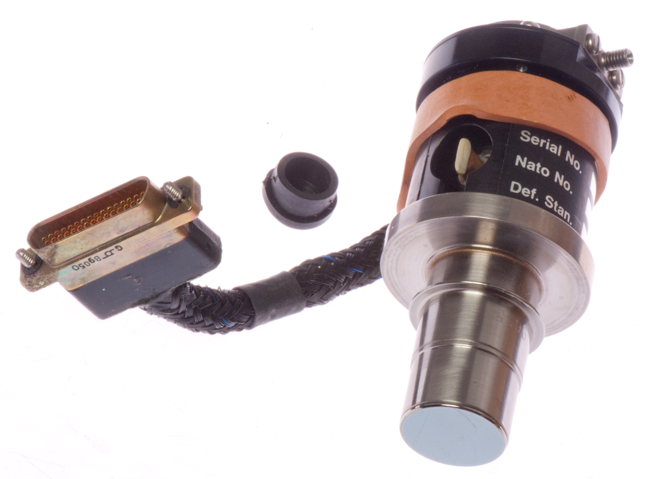
Fig 18 Infrared (IR) two row cryogenic high pressure gas cooled sensor. Plug covers pinch tube, probably for vacuum around front side of sensor. Note input window looks like a mirror in visible light.
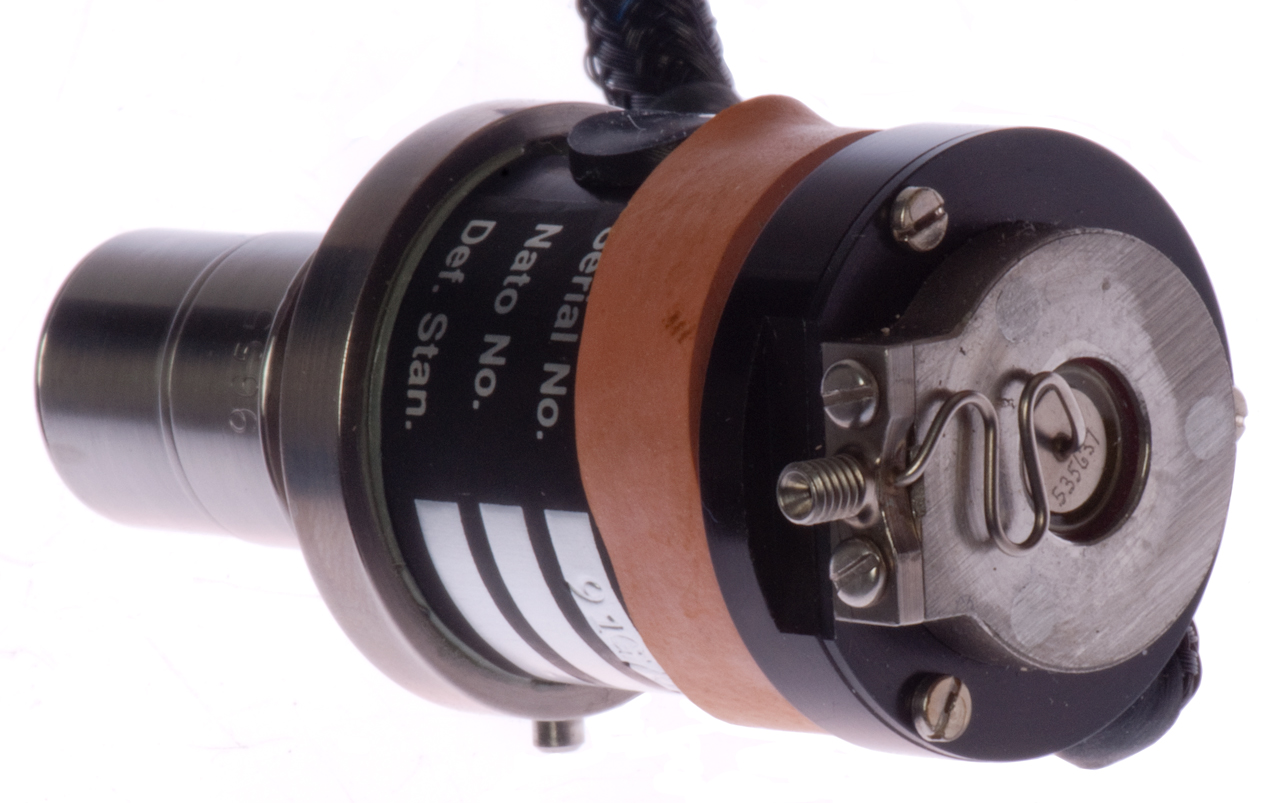
Fig 19 Infrared (IR) two row cryogenic high pressure gas cooled sensor. Fitting is for high pressure gas.
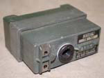
Fig 20 12 Volt specialized battery


Comments
I received email from Ole-Edvart Skeie who has a working unit. Here are his comments:
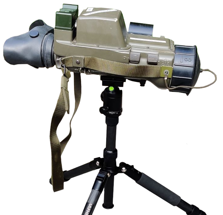
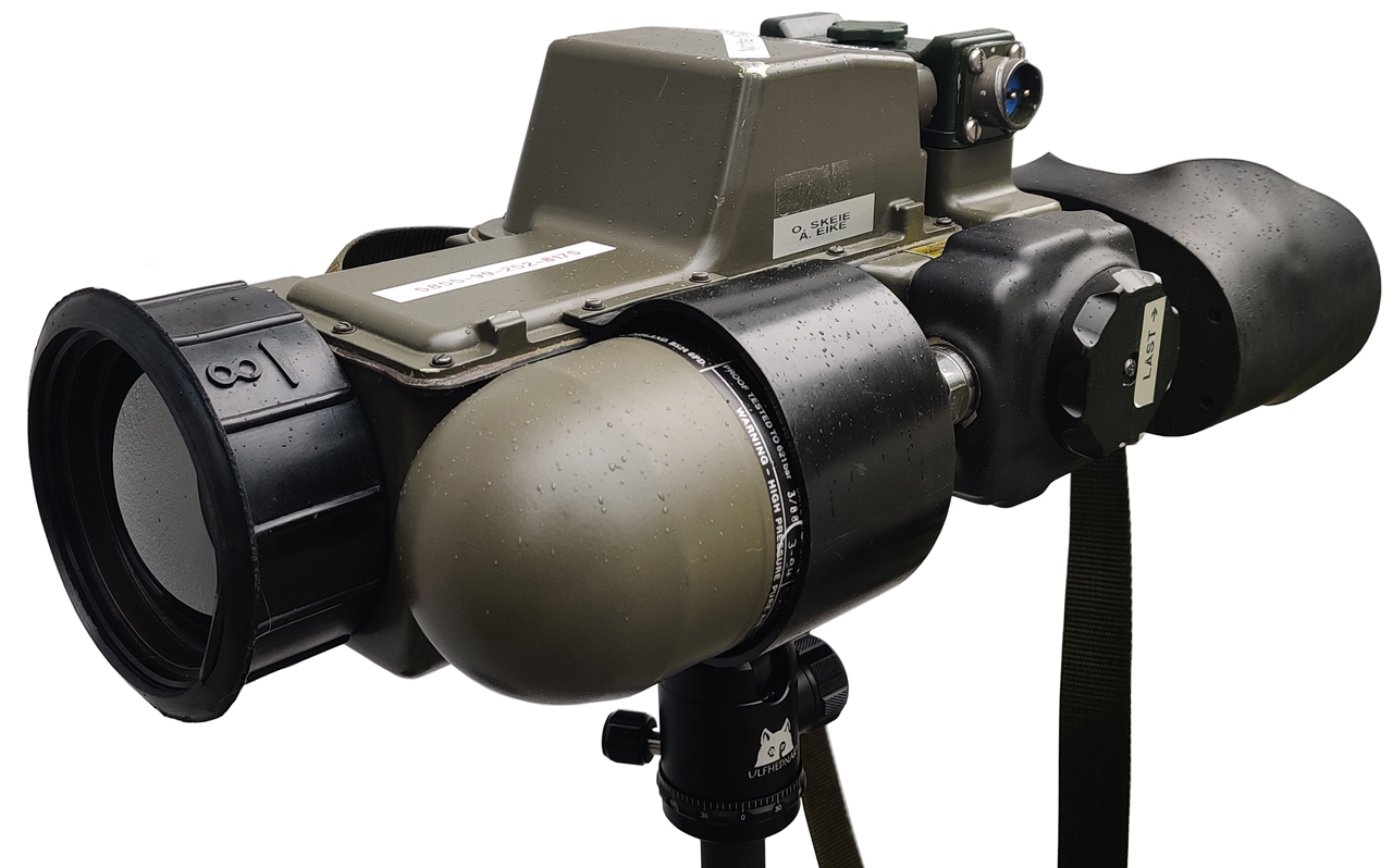
Fig 100 Shown on civilian tripod.
Fig 101
Fig 102
Fig 103
Fig 104 Timing
Fig 105 Principles of Operation
Fig 106 Scanner Module
Fig 107 Source and Sensor
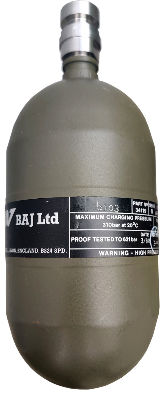
Fig 108 Factory Tank
NSN: 8120-99-225-3607
H.E.C. QAD 209-013 1-M532
If you know the name of the high pressure fitting
let me know.
Fig 109 Factory Tank Installed
Tank:
NSN:225-3956 3290
ISSE VBIG 791
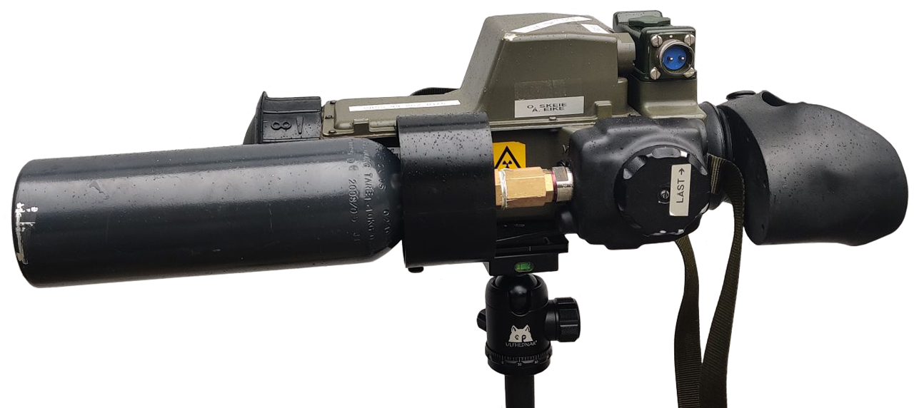
Fig 110 User supplied tank
I stumbled across your website while researching my HHTI. Thanks for the good reference photos, although I do see you are missing some parts in your example.
Just last week I bought one in working order, which I received this Monday. It’s in perfect working condition, with some slight wear on some rubber parts and minimal wear on the Germanium front «lens». It had been converted by the previous owner from its proprietary battery packs to run on standard 12V phone batteries, but due to his subpar soldering job, it quickly short circuited and we had to pull the top cover off to replace the 1.0 A glass fuze. It was a quick job (although we were very uncomfortable with breaking its cover seal in a suboptimal room with no sterile atmosphere), and after soldering together 3 x 18650 cell batteries (total voltage 11.1 V and 2950 mAh Power) it booted up with no hiccups, fed air right away, and we got a crystal clear image after waiting 10 seconds for the cooler to achieve optimal temperatures on the sensor array. The manual states the running temperature is -196 C (77 Kelvin or -320 Fahrenheit), achieved by the direction of compressed breathable air through a cooler in which the air turns liquid when being forced by the seeker itself. It operates from a 300 bar, 0,6 litre clamp-in air bottle. We have it hooked up to use a slightly bigger flask at 1 litre, but 200 bar max. The running time achieved with the bigger flask at 125 bar was about 1.5 hours. Manual states 4.5 hours with the original 300 bar/0,6 litre one. We'll be trying the original as soon as we get it pressure tested and certified for refills.
The imager has selectable FOV (wide/narrow), its power switch goes through (top to bottom) "OFF", "INVERTED" (Black-hot) and "NORMAL" (Red-hot), brightness and contrast have very wide ranges of adjustment, the focus range is not as impressive but still good enough for most ranges we tried (10-500 meters). There is also a MANUAL-AUTO selector for the thermal imager, although we're not 100% sure what exactly it does yet ;-) The manual is the original one of some 200 pages.
The mirror polygon spins at 8000 rpm. The two tilting mirrors tilt at a rate of 1:6 to the polygon's spinning rate (i.e. 1333 tilts per minute) and can be felt moving during powering down/up the imager (a rocking motion).
The two magnification settings linked to wide-FOV and narrow-FOV are 2x and 5x respectively.
The tripod mount is an unique one, and the tripod itself and its mounting-angulation head was made by Instro Precision of Kent, England.
HHTI = handheld thermal imager. The manufacturer (Thorn EMI of England, since divided up into other companies) uses this HHTI abbreviation as the name for the imager. The full name is "HHTI DFOV", or "handheld thermal imager, dual field of view".As you speculated on the page the "lens" is indeed a Germanium one.
I see some differences between our models. Yours has an input port on the top cover for direct powering from an external source in addition to the battery socket, while my model has only the battery socket.Notice that the NATO/aviation 2YM YTK 2-prong plug socket has been retrofitted onto the battery housing as a means of recharging the retrofitted battery pack. It reuses the old one-time use battery pack that was on the imager when it left Danish military service sometime after 2006 and found its way to Western Norway. The DYMO label on the top cover reads "New filter", as in the air filter cartridge in the rear (user end) of the top cover bulge. My example was built in 1988, the air bottle was checked in 1988, 1992, 1996, 2003. The filter cartridge was last changed in 2006 but still displays "fresh/dry" (blue line, while pink line signals "spent/humid" filter).I'll attach some images. The photographs taken through the image do not represent its true quality, it's quite difficult to take a photo through the dual rubber eye cup and focus properly. While running, the refresh rate of the display is visible through the digital sensor of the camera, as a set of moving lines. To the naked eye, it's much less visible and when pushing the face correctly into the eye cup, blocking external light from hitting the display, it's very clear with no blue tones.
I'll describe the start-up procedure, in case you are interested in adding it. It might be useful for other owners that might find your website.
- The battery is inserted and connected
- The air bottle is inserted firmly until it clicks into the jaw retainers, with the air valve wheel in "closed" position (in-between the spring-loaded leftmost position and the locked rightmost position)
- The FOV switch on the right hand side is set to WIDE mode
- The A/M switch on the left hand side is set to A for automatic
- The power switch (big knob just right of the eye cup) is set to the downward position, i.e. position 2 ("NORMAL" or RED-HOT)
- Operator waits until the spinning-up of the prism assembly is heard
- The LOW AIR indicator (yellow, bottom of display) should now light up
- The brightness switch is set to "neutral", with the longitudinal line set horizontally aligned with the sun symbol
- The contrast switch is set to "max", i.e. fully rotated clockwise
- The air valve wheel is rotated fully clockwise, which extends the plunger, allowing air to flow freely through the valve and enter the cooler tube
- The operator hears the initial stream of air move through the cooler, exiting in the escape valve. This takes about 5 seconds with the air in a "flush flow".
- After 15-30 seconds, depending on atmospheric temperature, the cooler reaches optimal temperature, and restricts air flow to "continuous flow".
- The operator now adjusts field of vision, contrast, brightness, auto/manual adjustment, and focus as he sees fit for his use.
To shut down:
NB! On shut-down procedures:
- Set the power switch to "OFF" (top position), after which the image is lost and the spinning-down of the prism can be heard.
- Close the air valve wheel by rotating it counterclockwise out of its locked position.
- The air bottle can then be removed by rotating it fully counterclockwise until it stops, then firmly pulling the bottle out.
The wheel is rotated slightly counterclockwise from its locked (rightmost position) until it clicks. This shuts off the valve.The wheel is then rotated all the way counterclockwise until it stops, then the bottle is firmly pulled out.


Patents
3728545 Infrared imaging apparatus, Honeywell Inc, Apr 17, 1973, 250/334, 348/E03.1 - early mirror scanning, not this device
3742238 Two axes angularly indexing scanning display, R Hoffman, TI, 1973-06-26, - front of mirror sends IR to detector, back of mirror sends visible light to eye/camera.
Related
Optics - optical patents - optical bench
Flashlights -
Binoculars in general Orion 9x63 astronomical (note with large (7mm) exit pupil diameter they work well at dusk and dawn)
C3 Infrared Signaling Telescope
PAS-6 Metascope IR viewer and source
T3C - Russian monocular Image Intensifier (star light scope)
TVS-2 Crew Served Weapon Sight
M18 IR Binoculars - near IR not hot people or car engines
M32 Periscope 105mm IR Gun Sight
MD-1 Automatic Astro Compass - also can see stars in the daytime
Astro-Compass for sighting Sun & stars
Periscopic Aircraft Sextant - Sun & stars
NextStar60 - cleaver microcontroller telescope using DC motors and shaft encoders
Orion - 9x63 binoculars - When the objective diameter (63 mm) is divided by the power (9X) if the exit pupil size (7 mm) is around 7 mm then the binocs are designed to be used with night adapted eyes, like for looking at the stars or to see things on the ground you could not see with bare eyes. I once watched a dear swimming while being chased by a dog just after Sunset. Although I could not see anything with my bare eyes, I could see fine with a pair of 7X50 binocs. See my Binoculars page for more on star gazing binocs.
Celestron 8" Telescope with Equatorial wedge and tripod- This model has a clock drive but no computer control. It's big and heavy, not something you pull out for a quick 5 minute look up. Would be much better if used with a permanent pier. It takes quite some time to do a Polar alignment, but when done you can find about anything just using the hour angle and declination scales.
Cloud Detection - as part of weather forecasting like used as part of an automated observatory - depends on far infrared (IR) sky brightness
Hughes Probe Eye infrared (heat) IR viewer - uses compressed gas for cooling
Shadow or Projection Clocks
PVS-4 Starlight Scope
PVS-5A Night Vision Goggles
UAS-4 Infrared Surveillance System, AN/AAS-14 Infrared Detecting Set, MK-898/AAS-14A Optical Filter Kit
Links
PRC68, Alphanumeric Index of Web pages, Contact, Products for Sale
Page created 29 April 2015