2 Aug 2004 Still Looking for all of
these.
ARN-83
Airborne automatic DF set 190 to
1,750 Khz. "Golden Age" construction using transistors and
discrete components. This LF DF set has been used on both
choppers and fixed wing aircraft including the A-37, C-2, UH-1,
AH-1T, VH-3A, OH-6, P-3, S-3, OV-10, U-8F, U-21A, 727 &
others.
Main components:
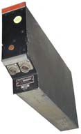
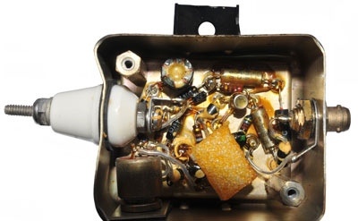
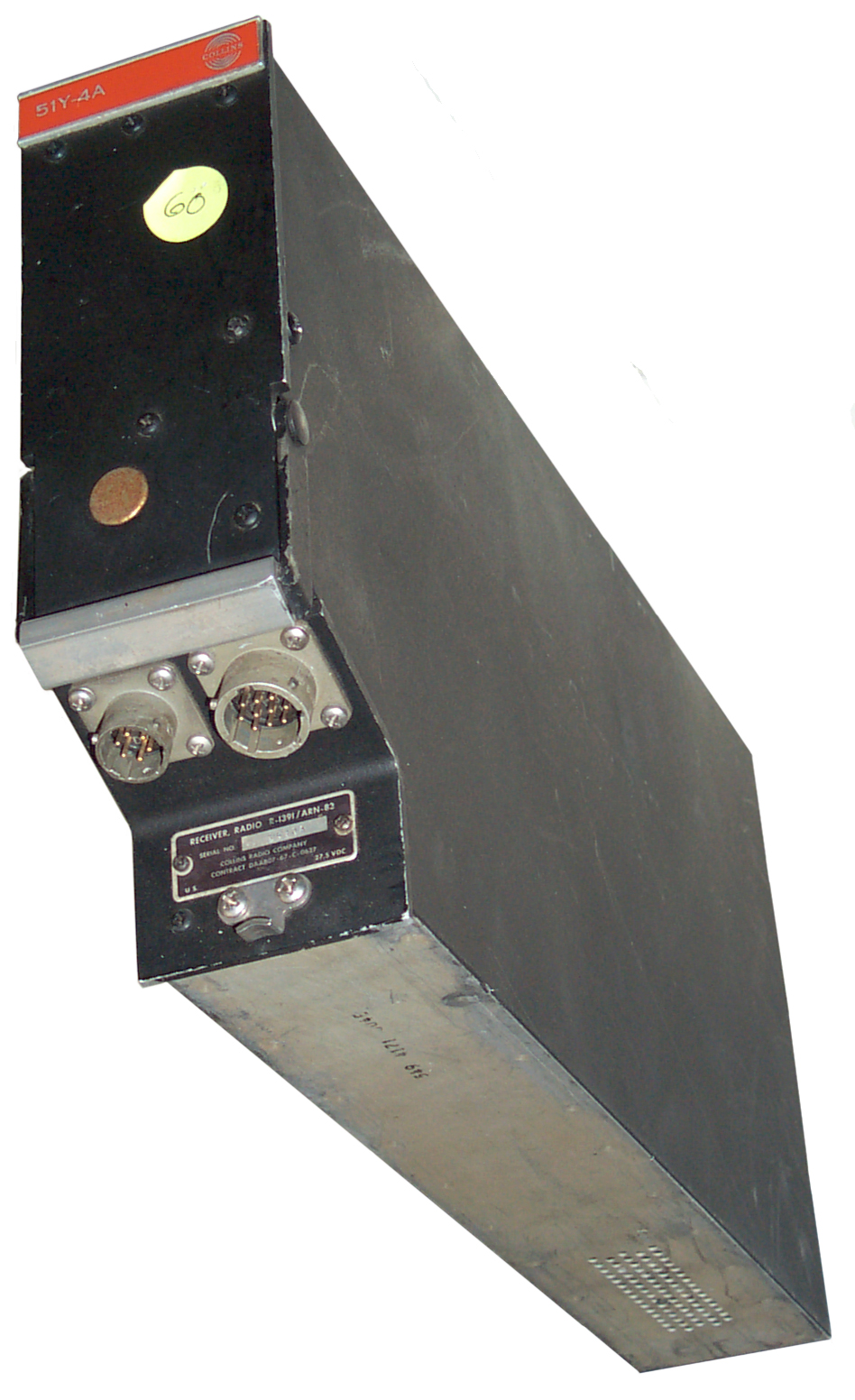
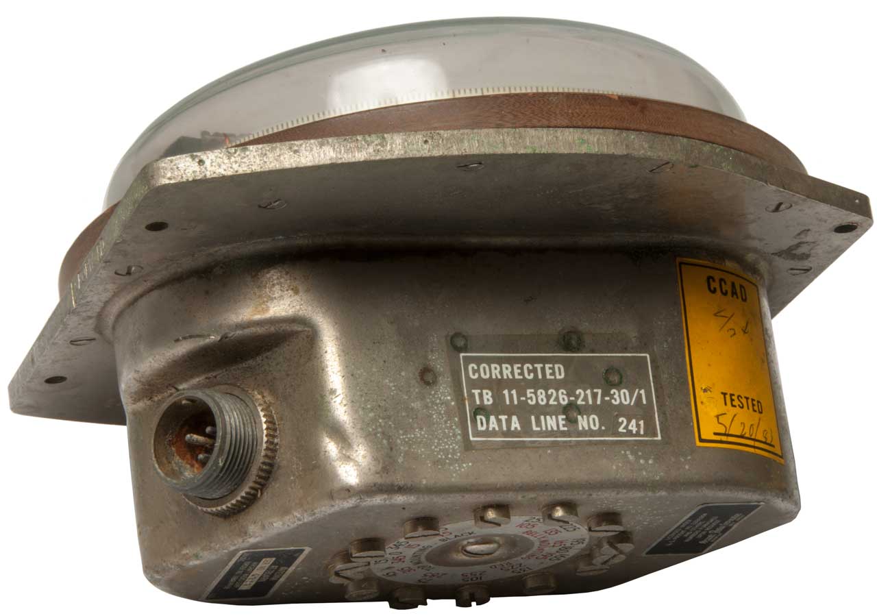
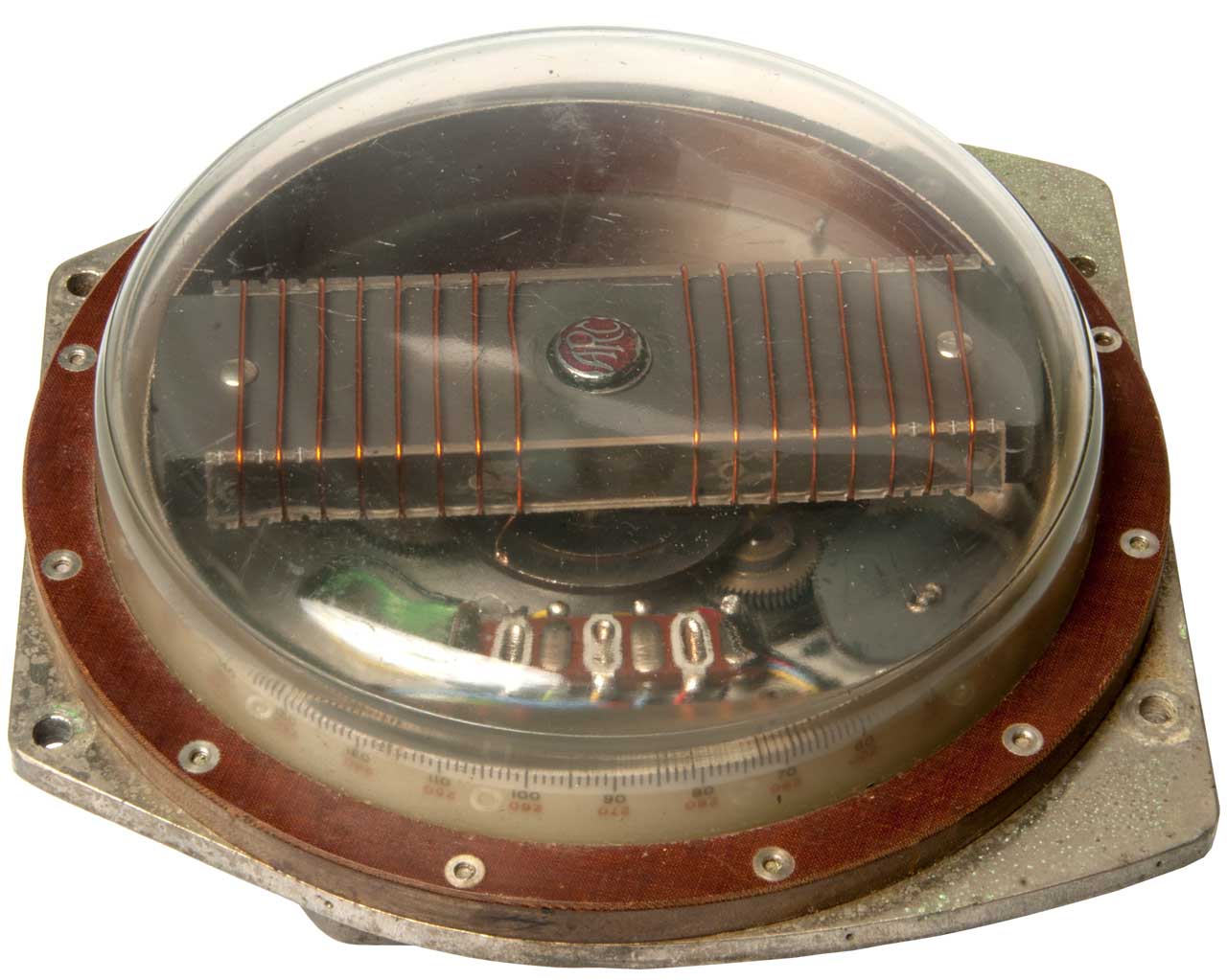
 R-1391
receiver
(Collins
51Y-4A)
Capacitor C1 is a 5 section air variable that's driven with
a motor and gear train. The band switch is also motor
driven. Construction is "golden age" with a number of
transistors in sockets.
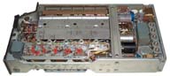
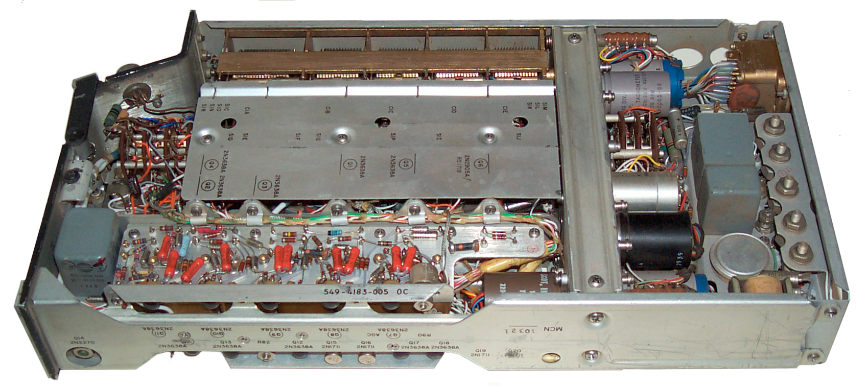
R-1391
receiver
(Collins
51Y-4A)
Capacitor C1 is a 5 section air variable that's driven with
a motor and gear train. The band switch is also motor
driven. Construction is "golden age" with a number of
transistors in sockets.
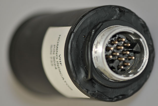
Three connectors:
J1 = Loop Antenna Input BT02A-12-10P pins A, C, E, G are
ground. pins F&H are Loop 1, pins B&D are loop 2
(Inductance compensator is between antenna and receiver).
J2 = Sense Antenna Input BT02A-10-6P Pin A is 220 uuF antenna
input, C&E are ground pin F is for a 150 uuF sense antenna.
J3 Cannon 38 pin "D" shell connector that mates to the MT-3605
mount. The mount has the DC to AC inverter. The
control and power wiring goes through J3. The manual loop
control (CW or CCW) wiring changes depending on if the antenna
is mounted to top of or below the aircraft.
- MT-3605 Mounting (w/27.5 VDC to 26 VAC 400 Hz inverter)
- C-6899 Control @ BPB
Surplus
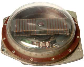
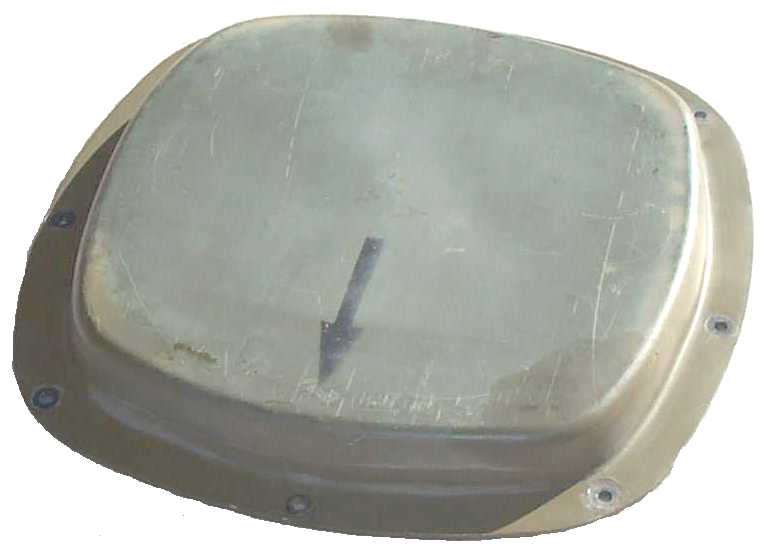
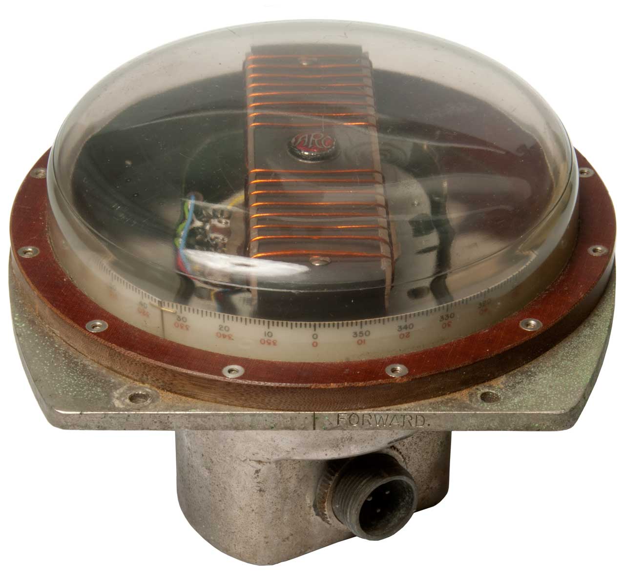
- AS-1863 Loop Antenna
passive Loop Antenna (4 ferrite
loopsticks, no amp) NSN 5826-00-985-917 The connector is
probably the same as the one on the receiver, a BT02A-12-10P.
16" long, 12" at widest section, < 1" high.
<>
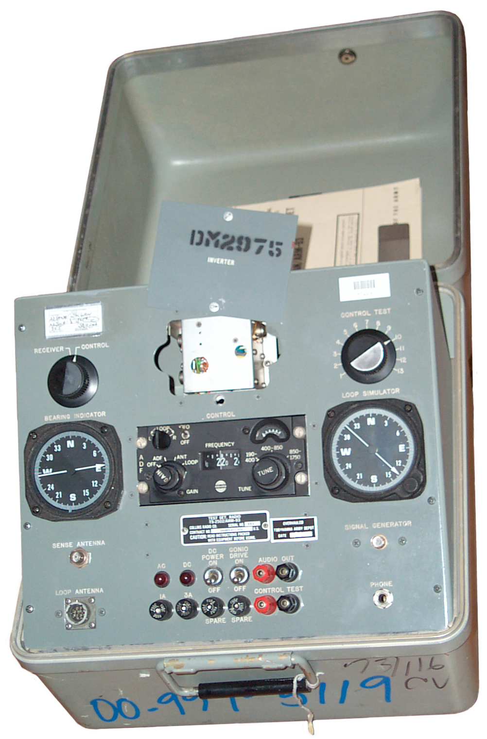
- ARM-93 Test Set.
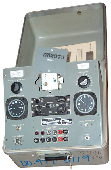
Info on using the ARM-93 test set.
TM 11-6225-821-12
TM 11-6225-821-40P
To use this test set you also need:
27.5 VDC @ 1.5 amp power supply, HS-33 headset or other 1/4"
phone plug type headset, signal generator in the 90 kHz to 1.8
MHz range,
TS-585 or equivalent audio
output meter, a meter with Ohms capability. This example
has a C-6899 control and the DC to 400 cycle AC inverter
installed and so can be powered by just the DC supply.
When the C-6899 is installed the front panel is called the
TS-2052/ARM-93.
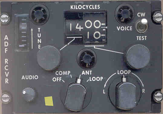
Control Panel
The control panel is held in place with 4 each Dzus 1/4 turn
fastners and the test set cable is terminated with a
KPT06B20-41S mil circular connector. The control panel is
marked ADT Control, Type 614L-8, CAT.A TSO-C41a TSO-C41b,
Collins p/n 522-2357-021. There is no C-xxx number on the
control.
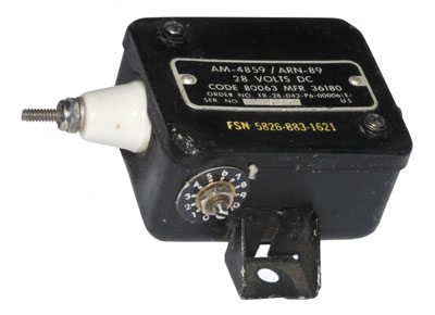
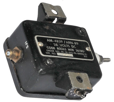
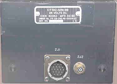
CV-2128 Inverter
Part of the MT-3605 mount that holds the R-1391 receiver.
Converts 27 Volts DC into 26 volts AC at 400 Hz
MT-3667 Antenna Q-meter adapter
An antenna adapter stored in the lid that allows attaching the
loop antenna to a
Q-meter, like the
Boonton 160, or other Q-meter that has the standard Q-meter
arrangement of banana jacks to the top. A switch on the
adapter allow checking the N-S or E-W antenna coils.
The condition of a loop antenna could probably also be checked
using a flyback tester.
Cannon Connector
The manual mentions CX-11570 as being a 10 pin to 10 pin cable
to allow connecting the receiver to be tested. But there
is also another larger cable called a "pendant cable" with this
connector that mates directly to the receiver. The
connection on the pendant cable is a functional equivalent of
the connector in the mount.
Operation
It may be that after powering up the test set from
27.5 VDC and switching to "Control" that by changing the
control frequency the Bearing Indicator will point to
different bearings at different frequencies. This is
part of the Quarterly PMCS. But before powering up the
test set I need to confirm the unmarked 2 wire cable is indeed
the DC power input.
The 821-12 TM has not information about what the 13 positions
of the Control Test switch are for.
Manuals
TM 11-1520-217-20-2 ?
TM 11-5826-225-12 ch 2 Direction Finder AN/ARN-83 (NSN
5826-00-912-4415) (ch 2 Jan 1966)
TM 11-5826-225-35 ch 5 Direction Finder Set, AN/ARN-83 (NSN
5826-00-912-4415) (ch 5 3 July 1980)
contains the receiver, control & inverter
test procedures to use with the ARM-93 test set.
TM 11-5826-225-20P nc Direction Finder Set AN/ARN-83
(NSN 5826-00-912-4415)
TM 11-5826-225-34P nc Direction Finder Set AN/ARN-83 (NSN
5826-00-912-4415
Info from an eBay ad in Jan 2015:
That set has been used in the following aircraft and more:
- Cessna A-37 Dragonfly
- Grumman C-2 Greyhound
- Bell UH-1 Huey
- Bell AH-1T Improved SeaCobra / SuperCobra
- Sikorsky VH-3A Sea King
- Hughes OH-6 Cayuse
- Lockheed P-3 Orion
- Lockheed S-3 Viking
- Rockwell OV-10 Bronco
- Beechcraft U-8F Seminole / L-23F Queen Air
- Beechcraft U-21 Ute / King Air
- Boing 727
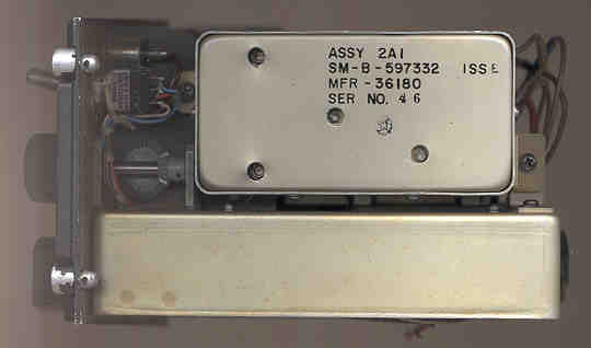
Comment on the test set in the eBay ad:
- Test Set, Radio, TS-250 / ARM 93 (the inverter is present,
as the last picture shows)
- Test Fixture, Loop Antenna, MT-3667 / ARM-93
- Simulator, Antenna, SM-446 / ARM-93
- All in the Test Set, Direction Finder Set, AN/ARM-93
Pressure Controlled Flight Case.
ARN-59
May be a much older tube type aircraft LF DF set.
YouTube:
T.F.
46 3200: Automatic Direction Finder
- U.S. Army Aviation Training Film (1961) -
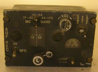
ADF REC
MC Band .19-.40, .40-.84, .84-1.75
COMP - ANT - LOOP
VOL
BFO-ON
LOOP<-->
Tuning Knob and lock
Signal Strength meter
DV-14 13/26 ARN-59 (125vdc 100ma, 13vac 800ma 100hz) (replacement
for P-14A)
Plug #16115 = 19 pins female, key left, screw ferrule. USA. Used
on ARC-60, K-13 Oscillator Relay, ARN-59 control.
ARN-59 D-F
Receiver 190-1750 KC TM 11-5826-217/204-*
R-836/ ARN-59 Receiver
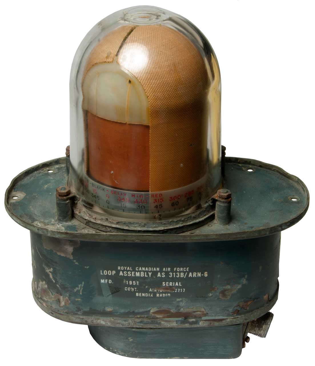
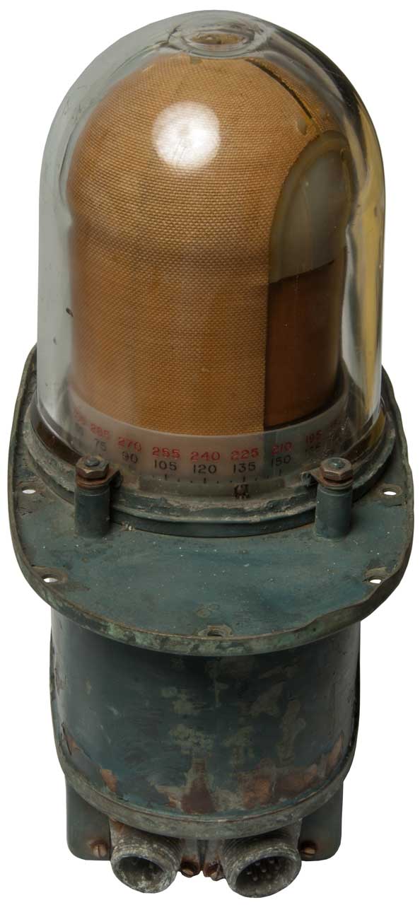
AT-382/ ARN-59 Loop, servo rotated, also has T-type wire Sense
Antenna.
AT-780/ ARN-59 Loop Ant
aka: L-11, p/n: 18000
Fig 0
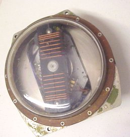 |
Fig 1
 |
Fig 2
 |
Fig 3
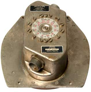 |
Fig 4
 |
|
Patents, RDF
related
|
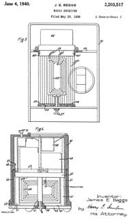 |
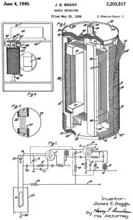
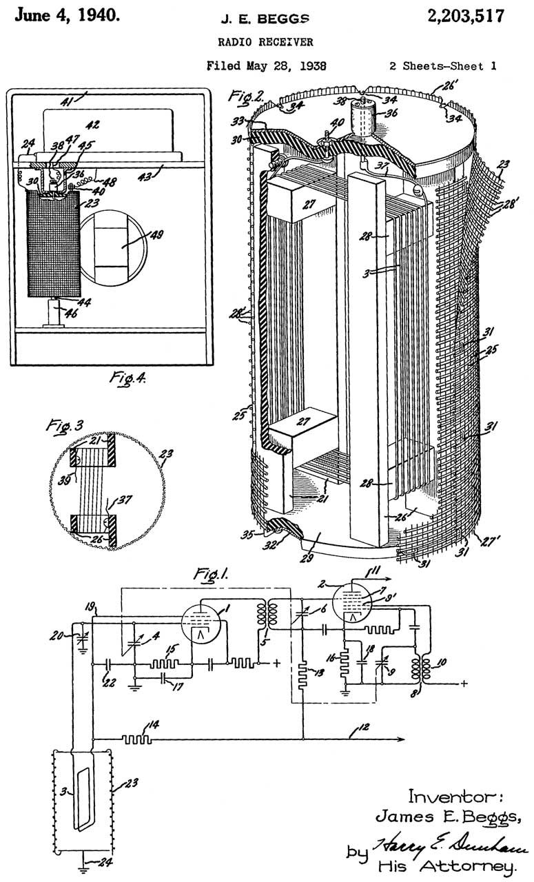
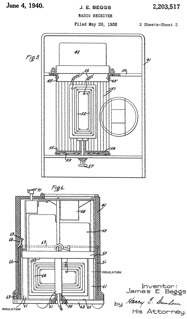
2203517
Radio receiver, James
E Beggs, GE,
1940-06-04, 455/193.2; 343/728; 343/842; 455/300;
343/748; 343/897; 455/289; 455/347 -
|
|
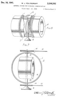 |
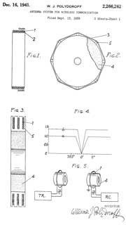
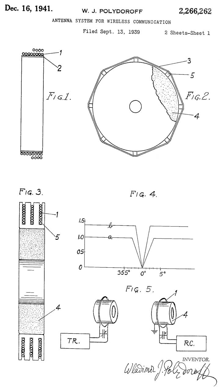
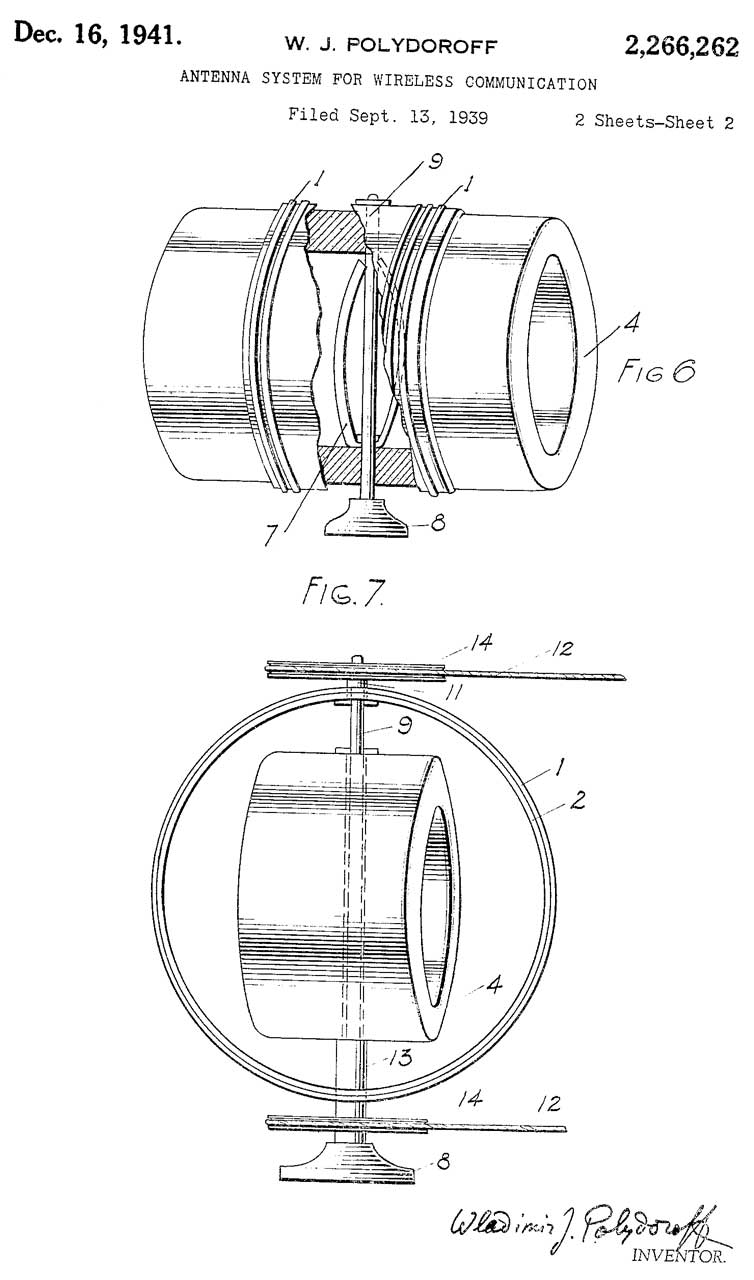
2266262
Antenna system for wireless communication, Wladimir
J Polydoroff, 1941-12-16, 343/764;
336/208; 343/748; 343/842; 336/183; 336/233; 343/788;
343/846 -
|
|
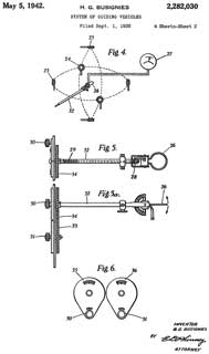 |
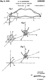
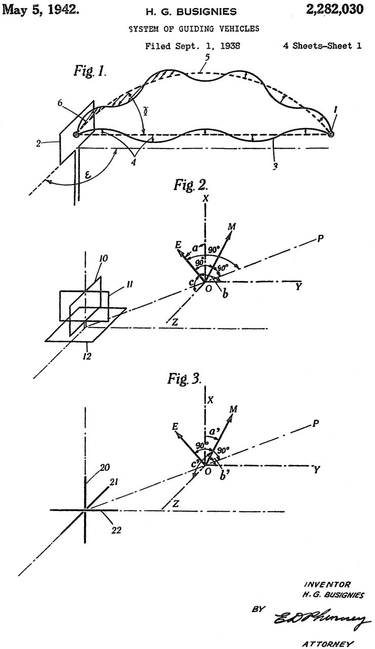
2282030
Busignies Henri Gaston, International
Standard Electric Corp, 1942-05-05, 342/432 -
This is RDF based on a loop (26) sensing the direction of
a transmitter.
|

|
|
2308521
Automatic radio direction indicator, William
P Lear, Lear
Aviation, App: 1939-07-27, Pub: 1943-01-19, -
|
|
 |
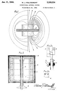
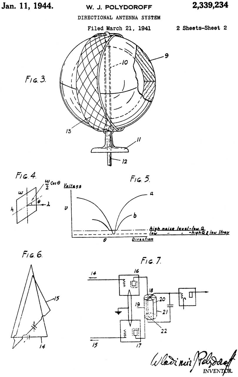
2339234
Directional antenna system, Wladimir
J Polydoroff, 1944-01-11, 343/788;
336/130; 343/869; 343/867 -
Delta to 2394787: Fig 2 with loopstick
|
|
|
2390543
Directional antenna system, Paul
H Kreager, Bendix
Aviation Corp, App: 1941-12-12, (W.W.II) Pub:
1945-12-11, -
|
|
|
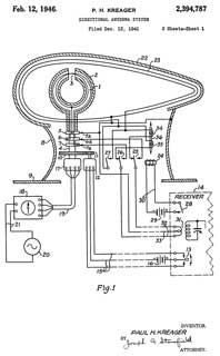
2394787
Directional antenna system, Paul
H Kreager, Bendix
Aviation Corp, App: 1941-12-12, (W.W.II) Pub:
1946-02-12, - LP-21
Delta to 2390543: Fig 2 no loopstick
|
|
|
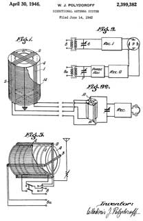
2399382
Directional antenna system, Wladimir
J Polydoroff, 1946-04-30, 343/788;
336/188; 343/867 -
|
|
|
2419480
Loop antenna shield, Robert
H Bryan, Truman
L Johnston, Stewart
Warner, App: 1944-05-18, W.W.II, Pub: 1947-04-22, -
"Another object is to provide an electrostatic shield that
will shield the loop antenna electrostatically in any
position without producing undesirable nulls in the
received directional signal." |
|
|
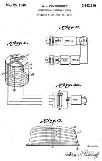
2442310
Directional antenna system, Wladimir
J Polydoroff, 1948-05-25, 343/788;
336/188; 343/867; 343/842 -
|
|
|
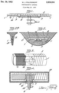
2624004
Ferromagnetic antenna, Wladimir
J Polydoroff, 1952-12-30, 343/788;
343/842; 343/873; 336/84R; 343/867 - |
|
|
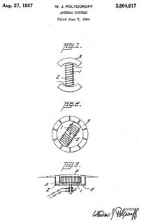
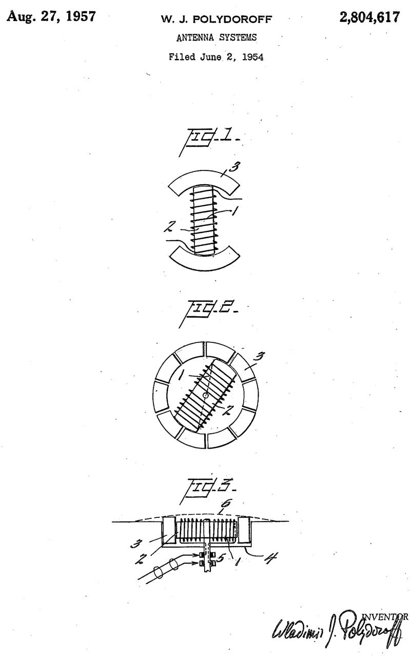
2804617
Antenna systems, Wladimir
J Polydoroff, 1957-08-27, 343/788 -
|
|
|
2939138
Bearing correction means for a direction finding antenna,
John
R Rennels, Collins
Radio Co, 1960-05-31, 342/420;
343/788 -
|

|
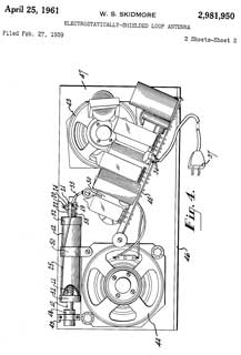 |
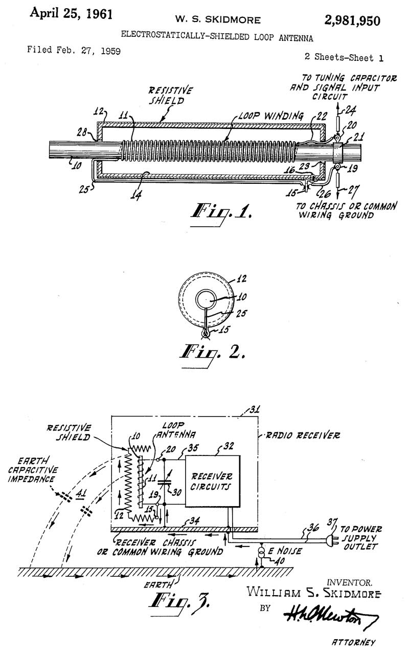
2981950
Electrostatically-shielded loop antenna, William
S Skidmore, RCA,
1961-04-25, -
|
|
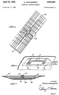 |
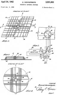
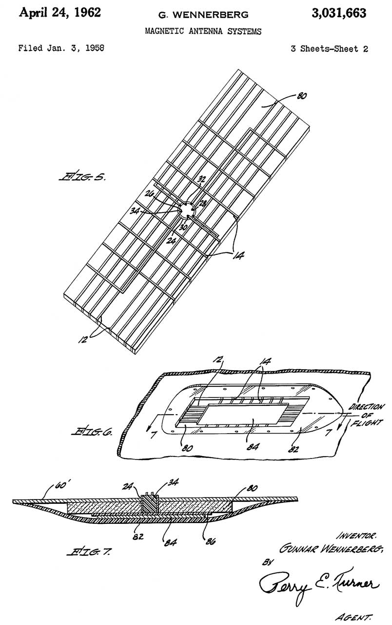
3031663
Magnetic antenna systems, Wennerberg
Gunnar, Motorola
Solutions Inc, 1962-04-24, 342/422;
343/705; 343/867; 343/788 -
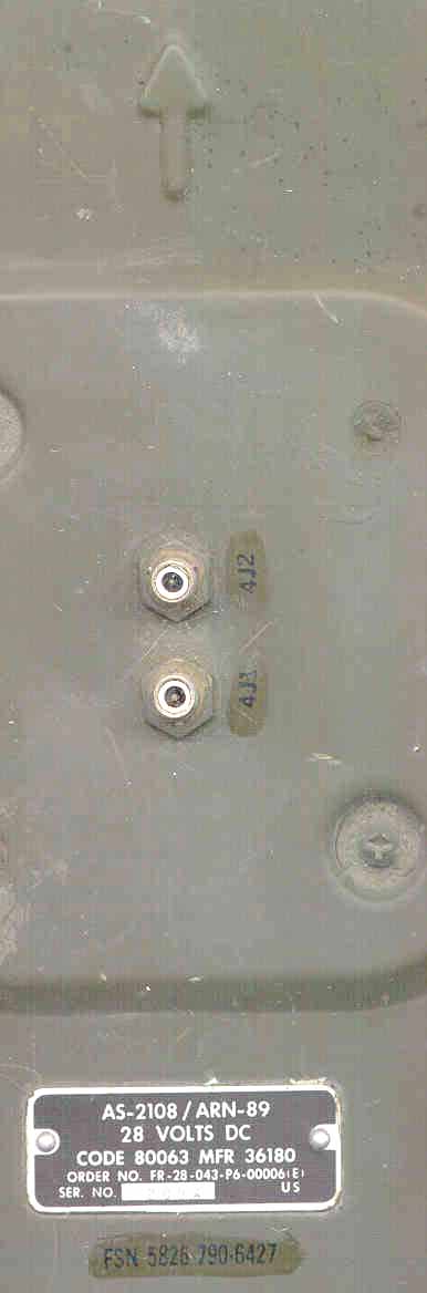
AS-1863/ARN-83 Loop
Antenna and/or AS-2108/ARN-89?
|
|
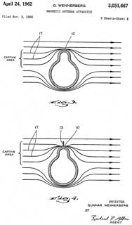 |
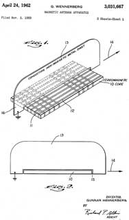
3031667
Magnetic antenna apparatus, Wennerberg
Gunnar, Motorola
Solutions Inc, 1962-04-24, 343/788;
342/420 -
|
C-2275/ ARN-59 Control Box. Tuning, Loop Controls, S-Meter,
Volume.
CX-4232/ ARN-59 Cable for C-2275
DY-107/ ARN-59 Dynamotor 24 VDC to 110 & 125 VDC, 13 V 100 Hz
for loop
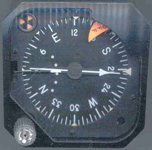
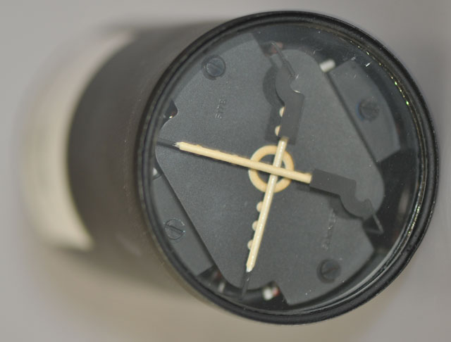
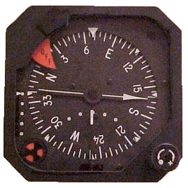
ID-637/ ARN-59 3" Compass Heading Indicator.
MT-1912/ARN Receiver Mount
MT-1913/ARN Dynamotor Mount
PP-4328/ ARN-59 PS, 28 VDC
S72-1759
Low Profile Ferrite Loop Antenna
designation-systems.net
- LF Direction Finder; used in C-2, C-130, RF-101, F-105, UH-1,
HH-3, SH/UH-3H, OH-6A, H-34, H-43, H-46, CH-47, CH-53D, O-1, OV-1,
S-2, T-37, T-38, U-1, HU-16, X-19; replaced by AN/ARN-89
[an error occurred while processing this directive] page created 16 Jan.
2001
 R-1496/ARN-89 Radio receiver, Direction
finding, 100-3000 KHz, AM CW
R-1496/ARN-89 Radio receiver, Direction
finding, 100-3000 KHz, AM CW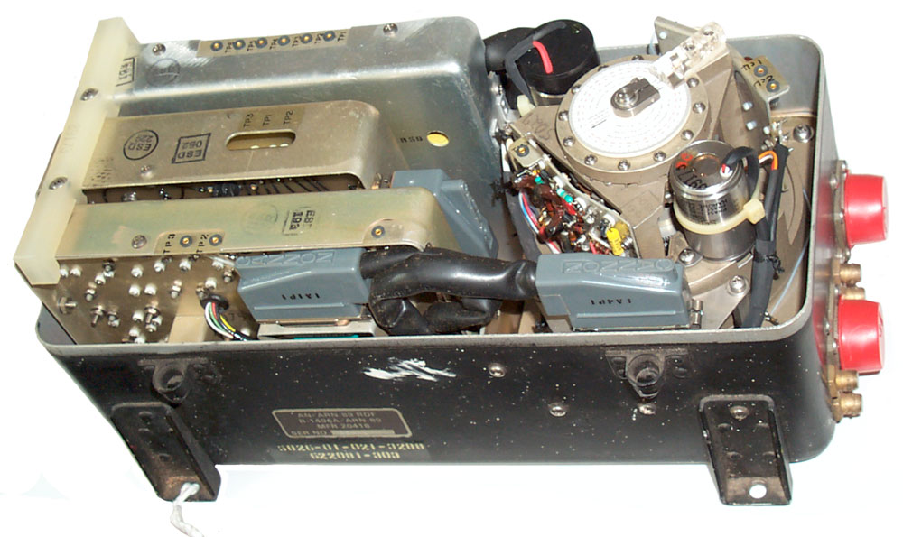


