Background
This Toy Engine
Commutator
Video
Electromagnet Analysis
Patents
Related
H-K Style L
Links
Background
Steam was the source of power that
drove the industrial revolution. Steam gave way to
combustion engines and electric motors as the source of
power. So you would expect that the men who knew steam and
how to use it would look to the newer technologies to see what
could be done.
The inventors of the Electromagnetic Toy Engine (see patent 882681
below) were Harry G. Hawekotte & Henry W. Klausmann both from
Indianapolis, Indiana. The five patents below have the name
of one or the other of the inventors of the Electromagnetic Toy
Engine. It's clear that these men know about steam machinery
and how it worked. The reversing feature on the Toy Engine
is a direct descendant of what's was commonly done with steam
engines. The Excavating Machine patent is based on a steam
powered "donkey".
If you know anything about Harry G. Hawekotte or HenryW.
Klausmann from Indianapolis, Indiana or who made this Toy Engine,
please
let me know.
Some of the other patents listed also use an electromagnet in an
engine that's made to appear similar to a steam engine.
This works since an
electromagnet pulling in an armature (i.e. a solenoid) operates in
a manner very similar to a steam powered piston.
A
Solenoid is a
cylindrical coil with an air core. Typically a magnetic
plunger is pulled into the core when the coil is activated.
An
Electromagnet is a
cylindrical coil with a magnetic core (typically soft iron or
electrical Silicon steel).
The company name was H-K based on the last names of the inventors
(patent
882681
Electromagnetic Toy Engine, H.G.
Hawekotte
& H.W.
Klausmann, Mar 24, 1908,
310/46
; 310/1; 310/83). This company made a large number of toy
variations that all used the flywheel and a pair of
electromagnets, i.e. the key patent.
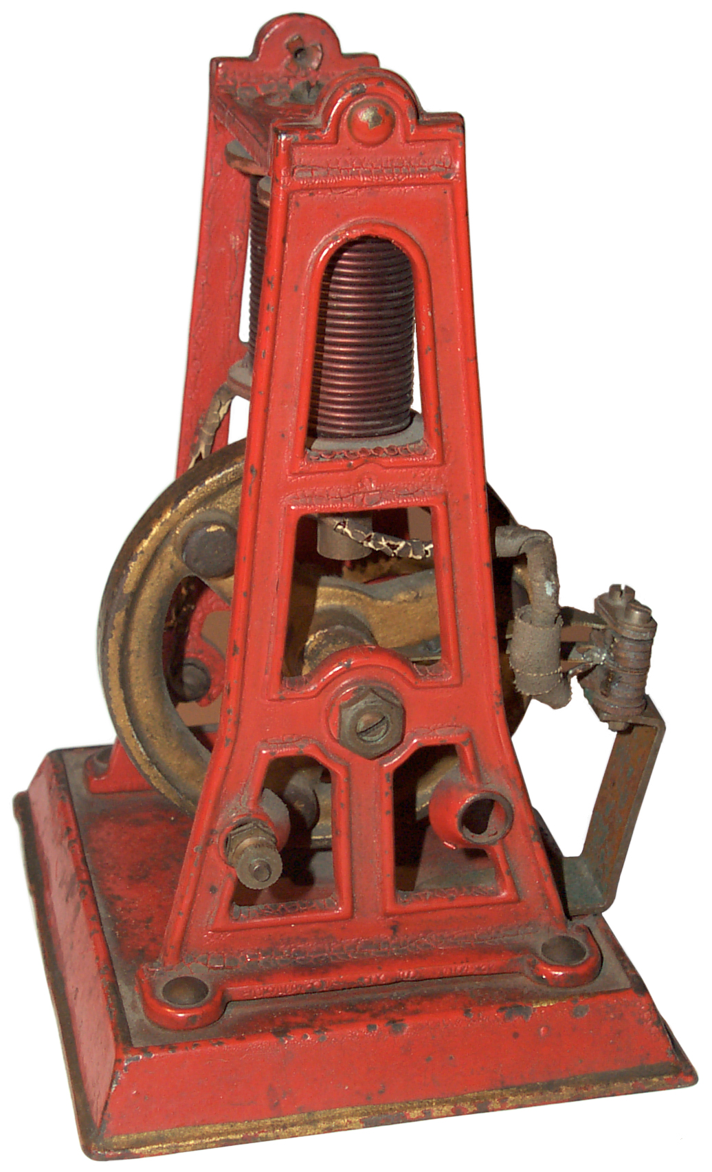
This Toy Engine
My interest is because this motor
uses Electro-magnets instead of the more modern rotating type
motor. Electro-magnets were the first electrical component
and were the foundation of the
Telegraph,
Stock Tickers, Teleprinters, district
alarms,
self winding clocks, Bells,
Buzzers, annunciators and many other things.
The thing that separates electro-magnetic toy engines from model
steam engines is the sound they make. Model steam engines
make some interesting sounds, especially those with more
complicated valving or auxiliary attachments. The
electromagnetic toy engines make a sound that's similar to a gas
engine and for me has more character.
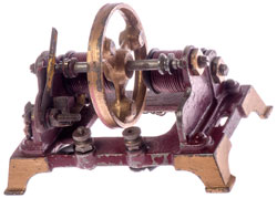
Arrived needing a cleaning and a little electrical repair.
The reversing lever was not fitted and the flywheel does not have
the 4 pins (left & right bumps) shown in Fig. 6 as "r".
There are a number of improvements from the details shown in the
patent. For example this Toy Engine has 3 armature bumps on
the flywheel and the patent shows 4. Tubular rivets are used
instead of screws and bolts. Sending current through a
moving joint is not a good thing. This was found to be
unreliable in clocks and I'm sure that's the case here. The
commutator leaf contact is similar to the
Hourly Winding Switch in a Self
Winding Clock Co. "Western Union" clock.
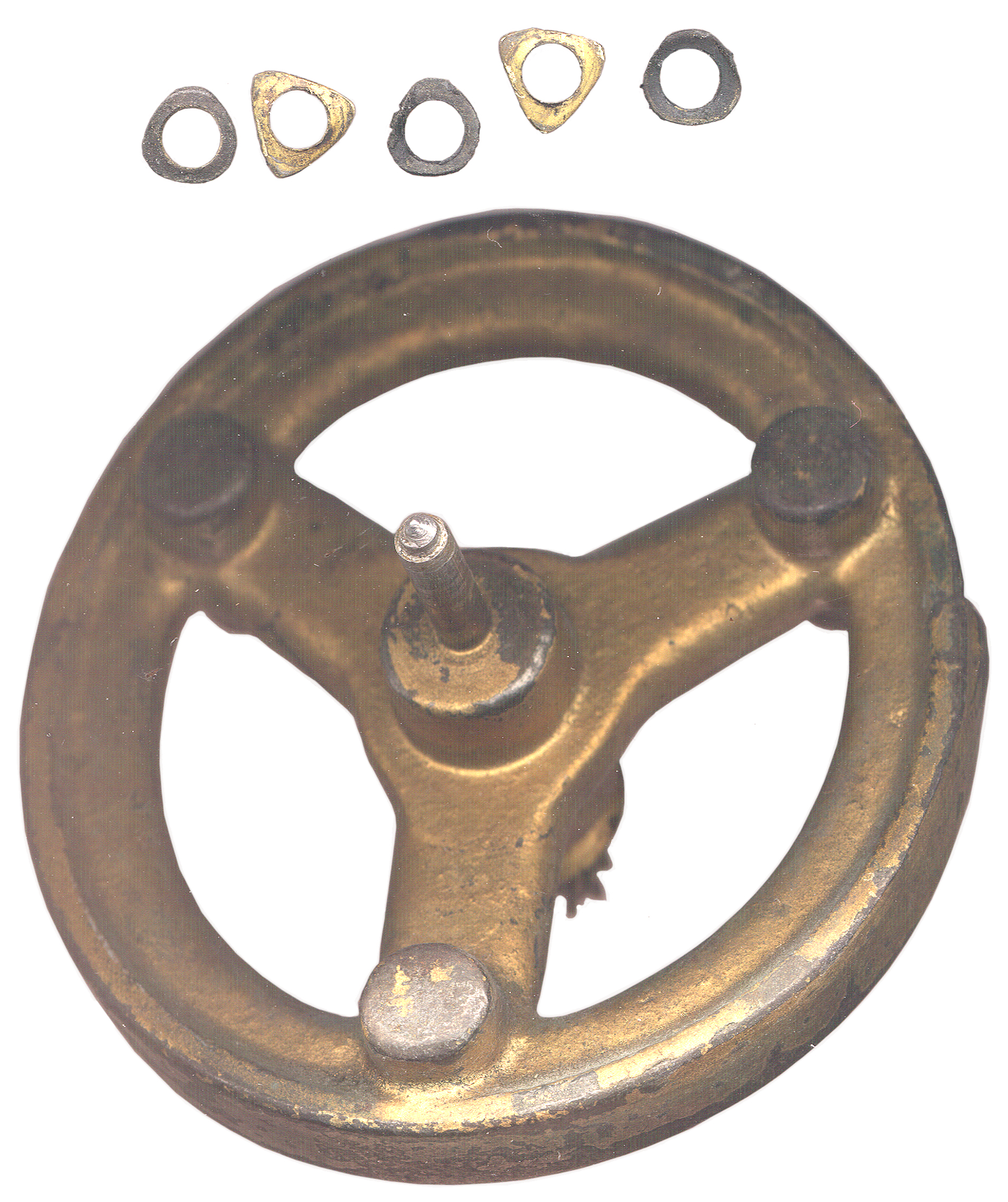
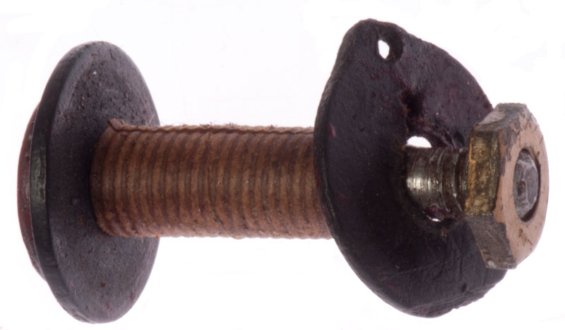
Commutator
This motor does send current through the spinning
flywheel. The lower leaf is an electrical conductor and
the upper leaf is a spring to press it down. On the
flywheel shaft (0.187" OD) there are 2 metal parts with three
lobes. These are surrounded by 3 black insulating
parts. The insulating parts are supposed to keep the lower
leaf from making contact except when the pointed lobe sticks
up. But the 3 black parts have worn down to the same shape
as the metal parts so this function is no longer working.
The triangular metal parts have a radius 40 mils larger than the
shaft at the low points and 100 mills larger at the high
points. If the insulating washer was half way between it
would have a radius 70 mills greater than the shaft, or 0.327"
dia with a center hole slightly smaller than 0.187". The
insulating washers are about 0.040" thick, but I don't think
that's a critical dimension.
How to fix?
Let me know
your idea(s).
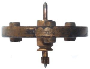
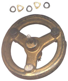
Here is an edge view of the flywheel with the communator parts
removed from the top shaft. There's a bump on the OD of
the flywheel a little to the left of center, not sure why it's
there.
Measuring the flywheel is sure easier when you have a couple of
123 blocks.
Getting It Working Step 1
I figured out that the insulating washers really are not needed
if the contact arm is positioned exactly in the right spot and
the cam is rotated to somewhere near the correct timing.
So after a little experimenting the engine is running, see video
below. At one cam timing the electromagnet turned on when
one of the bumps on the flywheel was between the
electromagnets. The power was so great I could not move
the flywheel (the frame was warping allowing one of the bumps to
tough an electromagnet). This says the motor can do much
better than what you see in the video if the cam timing is
adjusted properly and the electrical circuit does not have much
resistance.
I tried to use a bench supply good for 1 amp and the motor
barely could over come the frictional losses. I expect
that considerably more than an amp is flowing from the Energizer
529 volt lantern battery. The
529 data sheet
does not have any information about how much current it can
source. See Electromagnet Analysis
below.
It's interesting that the sound is very much like an engine
rather than like an electric motor. Every time the
electrical circuit is made there's a thump and a different kind
of sound when the circuit opens.
There is a lot of sparking at the contact points so a snubber
circuit is needed. There are a number of possible
circuits, but it will be interesting to see if one lets the
motor run stronger than another.
Video
2 minute video of Toy Engine
running.
YouTube
Electromagnet Analysis
Wire: 0.052" dia ->
AWG # 16 -> 248.9 feet/Ohm.
Winding dimensions: 1.575" long x 0.880 O.D. x 0.375
I.D.
30 turns on each layer and 5 layers:
Layer
|
Radius
|
Cirm
|
Layer
Len
|
1
|
.2135
|
1.34
|
40.24
|
2
|
.2655
|
1.67
|
50.0
|
3
|
.3175
|
2.0
|
59.8
|
4
|
.3695
|
2.32
|
69.7
|
5
|
.4215
|
2.65
|
79.5
|
|
|
|
300"
|
300" = 25 feet for a resistance of 0.100 per coil or 0.2 Ohms
total for the two coils.
Measured with HP 34401 in 4-Wire mode 0.093 and 0.129 for a total
of 0.222.
Measuring the voltage across both electromagnets (from the hot
coil thumb screw to the commutator leaf) and connecting the Fresh
6 Volt battery to the same two points using different wires (to
get a Kelvin connection) shows 1.7 Volts across the pair of
coils. This translates into a current of 8.5 Amps. The
current is being limited by the resistance of the clip leads and
the battery internal resistance.
The Red and Black leads connected in series measure 0.10 Ohms.
Reality check 6 Volts - 0.85 V (clip leads) - 1.7 V (coils) = 3.45
Volts. 3.45 V / 8.5 Amps = 0.4 Ohms for the battery internal
resistance.
Not accounted for are the resistance of the flywheel to frame
joint, the cam to leaf joint (where the sparks are) and the cam to
flywheel press fit joint.
While doing the above tests where the electromagnets were
energized bypassing the contact points it could be seen that the
electromagnets were strong enough to warp the frame and one of the
bumps on the flywheel would contact an electromagnet pole.
By placing a round tooth pick between the lower electromagnet
washer and the frame on each side the frame is greatly stiffened
and this problem goes away. You can see the tooth picks in
the Chapter 2 video above.
No. 6 Dry Cell Works
After measuring the wire supplied in the Built it Yourself! a Real
Electric
Motor Kit, the wire was
0.085 Ohms and the suggested power source was a single No. 6 Dry
Cell. Connecting an old No. 6 cell to this motor causes it
to spin up, not as fast as with the 6 Volt battery, but it's
running. A fresh No. 6 might be just what it needs
Snubber
Diode Across coil
This has the sound of putting a
brake on the motor and the flywheel seems to slow down.
The sparks at the cam to leaf contact go away, but at a high
price in terms of performance. See the Chapter 2 Video
above.
Resistor Across Coil
Most clocks that contain
electromagnets use a resistor with a value about 10 times the
coil resistance in parallel with the coil. When the
current source is turned off the coil generates the same current
in the opposite polarity. If there's an open circuit the
coil will develop a very high voltage to try and get to that
current. If a resistor is in the circuit the back EMF
voltage will be the source current times the resistor value or
about 10 times the coil voltage when being driven.
A problem with this method is the wasted energy during normal
operation of the electromagnet.
Capacitor Across Coil
Spark ignition engines have used a
capacitor across the primary of the spark coil since the early
1900s. The instant the points open the coil tries to
generate a current and it can do that through the
capacitor. As the capacitor charges up the coil is
decreasing the current. The voltage rating of the cap
needs to be able to handle whatever voltage the coil makes which
may be 10 or more times the source voltage.
Modern Control Circuit
It would be interesting to use a
modern control circuit that allowed dynamic adjustment of the cam
timing. I think this would result in much more power output and
maybe other features. I'm thinking of ways to do it that
would involve
opto electronics, power
MOSFETs, a
PIC micro controller and
an LCD display.
A simpler way might be a lever that pivots about the flywheel
shaft and carries a couple of photo sensors that detect the bumps
on the side of the flywheel. One photo detector turns on the
power and the other turns it off. By rotating the lever the
timing of the turn on can be changed and by moving the second
detector relative to the first one the duration of the on time can
be controlled.
Patents
The first electric motors are in class 310/46
132 Electric Motor, T. Davenport, Feb 25, 1837, 310/46 -
809 Improved Method of Changing Poles, Nelson Walkay, Jun 27 1838, -
uses Varnished copper wire (First magnet wire?)
1735
Electro-magnetic Machines, Truman Cook, Aug 25, 1840, 310/46
; 429/10 - commutation by Mercury cups
7287 Electromagnetic Engine, J.H. Lillie, Apr 16 1850, 310/46 -
7879 Electrical Motor, J. Neff, Jan 7 1854, 310/46 - 8 electromagnet
radial engine
7950 Electromagnetic Engine, T.C. Avery, Feb 25 1851, 310/46 - 4
electromagnets cause 'X" to rotate
14682 Electrogalvanic Machine for Producing Motion by Galvanic
Electricity, M. Vergnes, Apr 15 1856, 310/46 315/313
315/316 - hard to interpert drawings
58960 Electromagnetic Engines, A.P. Berlioz, Oct 16, 1866, 310/46
310/70R - 8 horseshoe PMs working aginst 16 EMs
63380 Electromagnetic Engines, C.J.B. Gaume, Apr 2, 1867, 310/34
- 12 pairs of EMs like a ferris wheel
671891
Electric Toy,Arthur A Kent,
marked "K & D" eBay 123379839991 Ba
69880 Electro-magnetic Engine, W. WIckersham, Oct
15, 1867, 310/46 -
78619 Magnetic Engine, L.C. Stuart, Jun 2, 1868, 310/46 - commutator
at center and at outside (each end of the EM)
80463 Electromagnetic Engine, A.J. B. DeMort, Jul 28, 1868,
310/46 -
87835 Electromagnetic Engine, C.J.B. Gaume, Mar 16 1869, 310/46 -
93689 Electromagnetic Engines, Aug 17, 1869, A.E. Dupas, 310/34
958354 Electric Motor, Charles E. Avery (Manhattan Electrical
Supply Co (see below)), May 17, 1910, 310/21
; 310/33 - has the look and feel of a horizontal single cylinder
steam engine
96332 Electromagnetic Motors, Nov 2, 1869, 172/36 310/46
318/372 - spinning and fixed EMs + fly ball governer
George holds many
printing telegraph
patents. This has a look and feel like an Edison motor used
in a printing telegraph
105663 Electromagnetic Motors, L. Finger, Jul 26 1870, 310/46 -
fixed and rotating EMs in drum arrangement
1084364 Windings for Electrical Machines, Emanuel Rosenberg, Jan 13,
1914, 307/16 ; 322/63; 322/92 - series, parallel tc wiring
112841 Electromagnetic Motor, H.M. Paine, Mar 21, 1871, 310/46 -
uses "circular box" to get stiff structure to allow for narrow air
gap
118561 Electromagnetic Engines, J.P. Tirrell, Aug 29, 1871, 310/46
- radial EMs, variable gap for speed control
RE4632 Electromagnetic Engines, J.P.
Tirrell, Nov 7 1871 - reissued
119899 Electromagnetic Motors, Oct 10, 1871, 310/46 - M.H. Utley
& A. Ross, 310/46 - Radial 6 U EMs rotate within 6 U fixed EMs,
2 metal leaf commutators
122944 Electromagnetic Engines, C.J.B. Gaume, Jan 23, 1872,
310/46 - 3 fixed U EMs work against a wheel where the EMs have a "T"
core to bridge the gap in the U
124868 Electro-magnetic Engine, W. WIckersham, Mar 9, 1872, 310/46 -
126628 Electromagnetic Engines, Moses G. Farmer, May 14, 1872,
310/46 - wide flat EMs interdigitated commutator
127369 Electromagnetic Motors, W.H. Richardson, May 28 1872, 310/46
- angled EMs each with it's own contact
129000 Electromagnetic Motors, J.S. Camacho, Jly 16 1872, 310/46
310/219 - ferris wheel with moving EMs parallel to axis
131377 Electromagnetic Motors, A. Schreiber, Sep 17, 1872, 310/46 -
two identical assemblies of 8 EMs, one fixed and the other rotating
1490125 Toy Electric Motor, O'Leary, Apr 15 1924, 310/21 ;
104/296; 105/150; 310/29; 446/462 - model railroad
152772 Electromagnetic Motors, W.S. Sims, Jul 7, 1874, 310/46
340/319 - the air gap is lengthened by making a sawtooth
153456 Electromagnetic Engines, H.M. Paine, Jul 28, 1874, 310/46 -
EM cores thin in radial dimension and long tangentially
153700 Electromagnetic Engines, L. Bastet, Aug 4, 1874, 310/46 - 8
spoked wheel with bars on end of spokes bridging gaps on 4 fixed Ems
155062 Electromagnetic Engines, L. Bastet & C.J.B. Gaume,
Sep 15, 1874, 310/46 - rotating "T" ends fixed EMs
155396 Electro-Magnetic Engines, Henry Van Hoevenbergh, Sep 29 1874,
310/46 - 2 side by side electromagnets attract
a "X" shape and cause it to rotate
156920 Electromagnetic Motors, C.J.B. Gaume, Nov 17, 1874, 310/46
-
156942 Electromagnetic Motors, G.M. Phelps, Nov 17, 1874, 310/46
- George holds many stock ticker patents
Used in a
stock ticker transmitter. When
the operator presses a key the motor revolves the shaft thus
pulsing the wire a number of time that depends on what character
is being sent.
163924 Electric Motor, C.J.B. Gaume, Jun 1 1875, 310/46 - 3
rotating radial EMs that are attracted to parts of the iron frame -
very simple
166431 Electromagnetic Engines, A. Tittman, Aug 3, 1875, 310/46 -
high wear commutation switches
166527 Electromagnetic Engines, C.A. Hussey, Aug 10, 1875, 310/46 -
PMs with "T" ends, sewing maching motor, non-sparking
1678397 Toy Electric Engine, Joseph
Koenig (Metal
Ware Corp, Wisconsin), Jul 24 1928, 446/397 ; 310/21;
446/484 - same company made No.
6 Dry Cell Lantern
YouTube:
Empire
Battery Powered B-32 Engine, 2:09 - run from 6V battery
A No. 6 Dry Cell is in a horizontal cylinder that looks like the
boiler,
There are two pair of electro-magnetic coils, one pair on each
side of the sheet metal armature,
The direction switch activates the left pair or the right pair.
446/397 is Amusement Devices: Toys/Sounding
310/21 is Electric Generator or Motor
Structure/Dynamo-electric.Reciprocating ..With other elements
...Pivoted or flat-spring armature
446/484 is Amusement Devices: Toys/Electric
Joseph also has a number of patents on Sterling Engines (
Wiki)
(aka: Hot-air motor, Hot-air engine) Published in 1925 -1926
XXXXXXXXXX Search for these XXXXXXXXXX
1632445 Toy Electric Range, Joseph Koenig (Metal Ware Corp,
Wisconsin), Jun 14, 1927,
219/394 - working heating
elements, switched by plug
1737050 Toy Electric Range,
1737051 Toy Electric Engine, Remus
Koenig (Metal
Ware Corp, Wisconsin),Nov 26, 1929, 310/21 ; 310/32;
446/484
YouTube:
Empire
B-33 Magnetic Engine, 4:14 - runs on AC line
Vertical faux boiler houses an AC line powered transformer
uses the same dual pair of coils hidden inside the sheet metal
"engine block"
172309 Electromagnetic Motors, J.H. Guest, Jan 18, 1876, 310/115
310/195 310/46 310/67R 451/294 - drum with coils, roller
commutator
173561 Electromagnetic Engine, W.E. Sawyer, Feb 15 1876, 310/46 -
long poles & Mercury cups
186642 Electromagnetic Motors, D. Ward, Jan 23, 1877, 310/46 -
horseshoe PMs and EM attracting iron bars
191781 Electromagnetic Engines, W.E. Sawyer, Jun 12, 1877, 310/46 -
toothed circular frame with 4 radial rotating EMs
192626 Stencil-Pen, H.M. Paine, Jul 3 1877, 74/56 310/46 -
a 4 radial pole Em rotates and a spiral ramp causes the pen tip to
move up and down
193385 Electro-magnetic Motors, A. Shedlock, July 24 1877,
195174 Electromagnetic Engine Commutators, W.E. Sawyer, Sep 11 1877,
310/46-planning for contact wear
211404 Electromagnetic Motors, C.A. Hussey Jan 14, 1879, 310/46
310/89 - rotation axis at right angles to axis of 2 fixed and
one central rotating EM
211985 Electromagnetic Engines, C.J.B. Gaume, Feb 4 1879, 310/46
310/269 - 3 radial rotating EMs work aginst 4 iron poles -
avoids back pull
217617 Electric-Motor, J. Hoover, Jul 15 1879, 310/46 - long
commutator with multiple contacts along axis
217807 Electro-magnetic Motor, J.C. Ludwig, Jul 22 1879, 310/46 -
reversing mechanism
219422 Electro-magnetic Motor, L.G. Wolley, Sep 9 1879, 310/46
- armature is EM which has almost 360 degrees of pole face two fixed
EMs or a PM
225395 Electro-magnetic Motor, J.S. Lamar, Mar 9 1880, 310/46 -
commutator on seperate shaft from motor
227622 Electro-magnetic Motor, W.W. Griscom, May 18, 1880, 310/46
-huge field winding or dual field winding, "I" shaped armature core
(Siemens)
231697 Electro-magnetic Motor, L.G. Wolley, Aug 31 1880, 310/46 -
258818 Electric Motor for Clocks, L.H. Spellier, May 30 1882, 310/46
310/49R - seconds hand ticks each second
259404 Electro-magnetic Motor, G. Little, Jun 13 1882, 310/46 -
might be related to stock ticker
263353 Electric Motor, D.T. Piot, Aug 29, 1882, 310/46 - ferris
wheel long skinny EMs
269888 Electric Motor, W.L. Silvey, Jan 2, 1883, 310/46 - makes use
of attraction and replusion
271502 Electric Motor, A. Millar, Jan 30 1883, 310/46 310/118
310/82 310/83 - radial horseshoe EMs operate on eccentric - complex
275392 Dynamo-Electric Machine, V.E. Keegan, Apr 10 1883,
278760 Rotary Electro Magnetic Motor, J.B. Atwater, Jun 5 1883,
310/46 - complex
279007 279008 Electric Motor, C.C. Peck & W.H. Chapman, Jun 5
1883, 310/46 - armature rolls on and in direct contact with pole
pieces
279045 Electro-magnetic Motor, W.H. Thomas, Jun 5 1883, 310/46 -
long skinny coils
284255 Electric Motor, L.W. Stockwell, 310/46 310/238
310/239 - similar to the toy motor kit,
but uses loops of wire for commutation
286873 Electro-magnetic Motor, S.F. Van Choate, Oct 16 1883, 310/46
310/67R -commutate by switching between two rings of EMs
291636 Electric Motor, L.W. Stockwell, Jan 8 1884, 310/46
244/135R -2 field poles 4 armature poles - continuous
attraction, not interrupted - modern looking
293556 Electric Motor, W. Bradbury, Feb 12 1884, 310/46 - no dead
spots so self starting
293929 Electric Motor, W.T. Waters, Feb 19 1884, 310/46 - 4 pole
armature 2 pole field wired to allow start/stop/forward/reverse
switching
294066 Electro-magnetic Machine, - generating electric power
294717
Electric Motor, M. Bacon assignor to the Novelty Electric Co, Mar 3,
1884, 310/46 - intended to be a toy, not a working motor
an armature with a number of legs
that are attracted to one of two electromagnets to rotate a shaft.
294817 Retouching Machine, C.H. Shaffer, Mar 1 1884, 396/655 310/46
- similar to the Stencil Pen above
298130 Electric Motor, L.W. Stockwell (Cleveland Electric Motor Co),
May 6 1884, 310/46 - calls 291636, improved armature winding and
brush arrangement
298922 Armature for Electric Motors and Dynamo-Electric Machines,
J.C. Vetter, May 20 1884, 310/46 310/268 - series magnetic
path
300648 Electric Motor, H.B. Sheridan, Jun 17 1884, 310/46 - dental
tools and sewing machines more torque at low speeds
302793 Electric Motor, E.T. Starr (S.S. White Dental Mfg Co), Jul 29
1884, 310/46 - control both speed and direction
306805 Electric Motor, J.B. Atwater, Oct 21 1884, 310/46 310/218
- old fashion looking ferris wheel type
307387 Electric Motor, W.W. Griscom, Oct 28 1884, 310/46 - calls
227622, changing polarity of filed as armature revolves
308534 Electric Motor, G. Trouve, Nov 25 1884, 310/46 - eccentric
(elypitical) faces on either a Seimans 2-pole armature or on the
field poles to make self starting
309522 Electric Motor, W.H. Chapman (Chapman Electric Motor Co), Dec
23 1884, 310/34 - cursrent flows in two paths
309562 Electric Motor, C.C. Peck (Chapman Electric Motor Co), Dec 23
1884, 310/34 -wedge shaped EMs
315161 Electro-magnetic Motor, C.G. Perkins (Imperial Electric Light
Co), Apr 17 1885, 5 parallel connected field EMs = 5 poles & 4
iron armature poles.
317249
Electromagnetic Reciprocating Engine, C.J. Van DePole, May 5, 1885 ,
310/34 ; 40/469
318589 Electric Motor, L.G. Wolley, May 26 1885, 310/46 -
321049 Electric Motor, J.M. Pendelton (Equitable Electric Co), Jun
30 1885, 310/46 - toy motor, 3-pole armature, similar to the Gilbert
323652 Electromagnetic Motor, M.G. Farmer, Aug 4, 1885 -
supposed to be a real motor
327797 Electric Motor, M. Immisch, Oct 6 1885, 310/46 - 3-pole
arm 4 pole Field with overlaping segments for equal pull
331880 Electric Motor, W.S. Hill, Dec 8 1885, 310/46 - uniform pull
332668 Electric Motor or Dynamo-Electric Machine, W. Main, Dec 15
1885, 310/46 310/164 - improved small DCmotor
describes two classes of motors and
their advantages and disadvantages
335998 Electric Motor, F.E. Fisher, Feb 9 1886, 310/46 -
338622 Electric Motor, G.H. Stout, Mar 23 1886, 310/46 - 2 field
poles with large EMs & 4 armature poles
338976 338977 Electro-magnetic Motor, V.E. Keegan, Mar 30 1886,
310/46 - calls 275392 but more poles and better symmetry
343176 Electric Motor, E.T. & D. Higham, Jun 8 1886, 310/46
310/180 - using two sizes of wire to get in more turns slot iron
armature
343441
343444 Electric Motor, J. Doyle, Jun 8 1886, 310/40R 310/46
- large horseshoe magnets
343487 Electric Motor, H.M. Paine, Jun 8 1886, 310/46 -
344262 Electric Motor, J.E. Emley, Jun 22 1886, 310/46 - bar rotates
inside coil
349563 Electric Motor, A. Bossard, Sep 21 1886, 310/46 -
349654 Electric Motor, V.E. Keegan, Sep 21 1886, 310/46 - cylindeer
with notches on end and coil is field, EMs armature
351229 Electric Motor, H. Walter, Oct 19 1886, 310/112 310/46
- side by side armatures with relative rotation of half of pitch
354111 Electric Motor, N.H. Edgerton (Edgerton Electric Motor Co),
Dec 14 1886, 310/240 310/46 310/49R - 3 pole armature, fork
commutator brush, enclosed design,
355024 Electric Motor, H.M. Paine, Dec 28 1886, 310/46 - modern
filed coil winding, two connected brushes on commutator
356878 Electric Motor, E.J. Huston (Thompson Huston Electric Co), 310/46
310/64 - laminated core made from this sheets insulated form
each other
362322 Electric Motor, R.J. Sheehy, May 3 1887, 310/46 - "X"
rotates over 3 EMs - might be stock ticker related
364086 Electric Motor, G.F. Card, May 31 1887, 310/46 -
improvement in Pacinotti type electric motors
366021 Electromagnetic Motor, H.M. Paine, Jul 5 1887, 310/46 340/319
- large Ems and leave gap
374580 Revolving Electric Hammer Tool, W.G.A. Bonwill (S.S. White
Dental Mfg Co), Dec 13 1887, 433/99 173/100 173/117 310/46
375560 Electric Motor, J.F. McLaughlin, Dec 27 1887, 310/46 - has
the feel of a stock ticker motor
382589 Electric Motor, G.F. Card, May 8 1888, 310/46 310/237
- looks like dental motor
------- Patents to Nicola
Tesla May 1, 1888 -------
385675 Electric Motor and Dynamo Machine, O. Lugo, Jul 3 1889,
310/46 - each EM is connected to others both in armature and field,
complex wiring
389207 Electric Motor, A.E. Eastwick, Sep 11 1888, 310/46 - 6 radial
EMs for armature 2 parallel EMs for field, C clamp for bench
mounting, laminated core,
391590 Electric Motor, J. Doyle, Oct 23 1888, 310/46 - improvements
to 343444
393373 Electric Motor, F.J. Keeler & J.W. Carnes, Nov 27 1888, 310/46
15/246 310/228 74/569 -
394075 Electric Motor and Dynamo Machine, O. Lugo, Dec 4 1888,
310/46 - 7 Field & 4 Arm or 4 field & 3 arm or 5 field &
4 arm EMs and their cross wiring
maximizing the number of magnetic
filed lines being cut done in pairs
395299 Electric Motor, D.F. Sweet, Dec 25 1888, 310/46 - maximizing
magnetic field
399059 Electric Motor, O. Lugo, 310/46 - more on the wiring, but
he's using long solenoid EMs
402290 Electric Motor, F. Yeiser, Apr 30 1889, 310/46 -
commutator looks like an automobile cam shaft
404465 Electric Motor, C.S. Bradley, Jun 4 1889, 310/166 12/142C
310/211 310/46 388/836 - instead of a PM or Em field magnet he uses
Focault currents derived from the armature
404533 Electric Motor and Regulator, A. Gartner (Continental Motor
and Electrical Co), Jun 4 1889, 310/46 - with fly-ball governor
406874 Electric Motor, J. Buckley, Jul 16 1889, 310/46 -
407272 Electric Motor, Leonidas G. Woolley, Jul 16 1889, 310/46
- may be rail road related since he was first to patent a RR
electric headlight-looks strong
411030 Combined Electric Motor and Blower, C.J. Hirliman, Sep 17
1889, 417/353 310/40R 310/46 310/66 310/67R 417/410.1
417/420 417/423.1
411833 Electric Motor, C.C. Peck (Giant Electric Motor Co), Oct 1
1889, 310/46 310/237 310/247 - for heavy work on railway
cars
419245 Electric Motor, S.C.C. Currie (United Electric Improvement
Co), Jan 14 1890, 310/46 310/220 - armature driven +, 0, -,
0, +
419808 Electric Motor, LeRoy S. White, 21 Jan 1890, 310/46 -
------- Patents to Nicola
Tesla Dec 3, 1889 -------
416191 Electromagnetic Motor, Dec 3, 1889,
318/734
416192 Method of Operating Electromagnetic Motors, Dec 3,
1889
416193 Electromagnetic Motor, Dec 3, 1889
310/172 ;
318/781
416194 Electric Motor, Dec 3, 1889,
310/166
416195 Electromagnetic Motor, Dec 3, 1889
538351 Electric Engine, L.M. Sabin, Apr 30, 1895,
310/24 ;
310/35 - for rail road use, two cylinders and a crank
555190 Alternating Motor, N. Tesla, Feb 26, 1896,
533108 Electric Motor, C. Writ, Jan 29, 1895, 310/19 ;
310/34 - more of a clock movement
------------------------ Patents Related to the Electromagnetic Toy Engine
-----------------
580505 Excavating Machine, J.L. Potter & H.G. Hawekotte,
Apr 13, 1897, 212/80 ; 212/115; 212/74 - Steam donkey add on
to make excavator
592779
Steam-Boiler, G.P Hawekotte, Nov 2, 1897, 122/172
812949 Electromagnetic Power Generator, Joseph L. Potter, Feb 20,
1906, 310/22 ; 310/33- appears to be of toy scale
858211
Electromagnetic Locomotive, J.L. Potter assignor to Harry G.
Hawekotte, June 25, 1907, 180/65.6
872251 Electromagnetic Power Generator, J.L. Potter assignor
to Harry G. Hawekotte, Nov 6, 1907, 310/21 ; 310/32 -
uses many conventional
electromagnets - going by the thumb nuts this may be a model
872511 Toy Aerial Swing, H.G. Hawekotte & H.W. Klausmann,
Dec 3, 1907, 472/7 - an electromagnet powered swing
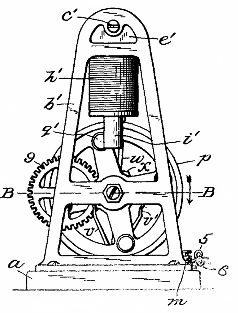
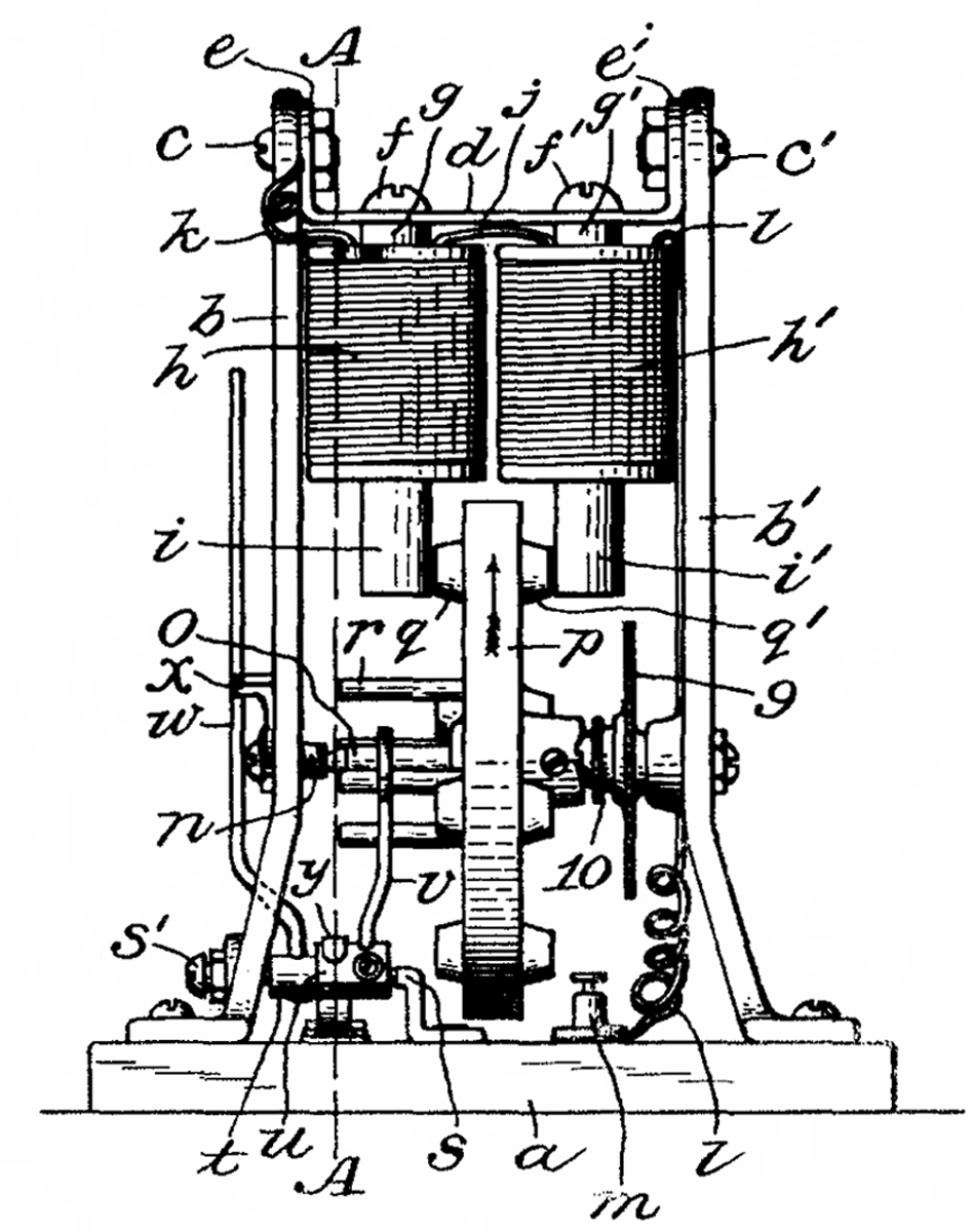
882681
Electromagnetic Toy Engine, H.G. Hawekotte & H.W. Klausmann,
Mar 24, 1908, 310/46 ; 310/1; 310/83 -
a flywheel is powered by two
electromagnets, one on either side. The comunating is done
by one of two contact arms selected by a level, the direction of
motion is reversed by throwing the lever. The output pully
is on a shaft that's geared down from the main shaft.
------------------------ End of Patents Related to the Electromagnetic Toy Engine ----------
1166688 Toy or Working Model, F. Hornby assignor to Meccano,
Jan 4, 1916, 403/218 ; 182/222; 403/169; 403/391 - basic
Meccano elements
D49308 Design for a Girder-Strip, F. Hornby assignor to
Meccano, July 4, 1916, D25/132 - basic girder for building
1196238 Motor for Structural Toys, F. Hornby assignor to
Meccano, Aug 29, 1916, 74/354 - spring wind clockwork motor
1202388 Toy or Working Model, F. Hornby assignor to Meccano,
Oct 24, 1916, 310/1 ; 310/237; 310/75R -
a single coil electromagnet, using a
laminated core, drives a rotating armature.
1223375 Electrical Toy, G. S. ELLIOTT, Apr 24 1917, 310/46 ;
310/236; 74/5.47-
1226835
Electrical Toy, A.B. Wilder, May 22, 1917, 40/421 ; 446/322
- No. 6 Dry Cell powers electromagnet causing parrot to rock back
& forth
1291819 Electric Motor, M. Fogel, A. Ascher, Jan 21 1919, 310/23
; 310/34 - has the appearance of a horizontal steam engine where the
electromagnet is inside the pseudo steam cylinder.
1760498 Toy Electric Motor, C.T. Hoffman, May 27, 1930, 446/397
; 310/21; 446/484
Has the appearance of a horizontal
stationary steam engine and makes a "gas engine sound".
2820160 Solenoid Powered Motor, E.E. Erie, Jan 14, 1958, 310/23
an electromagnet operating as a
solenoid oscillates back and forth as it drives a disk which turns
a shaft. The solenoid is only powered for a fraction of the
time so battery life is long. A No. 6 battery is shown as
the power source.
2894154 Electric Motor V.P. McVoy, July 7 1959, 310/23
; 310/34 - has the appearance of a stationary vertical steam engine,
supposed to be a real motor.
3469163 Moving Coil Direct Current Recriprocating Motor, J.W.
Mathews, Sep 23, 1969, 318/127 ; 310/27; 318/132
Crocker Wheeler Motor Patents
451884 Electric Motor or Dynamo-Electric Machine, S.S. Wheeler, May
5, 1891, 310/267
451885 Method of Constructing Field Magents, S.S. Wheeler, May 5,
1891,29/607 ; 269/269; 310/254
451894 Electric Motor or Dynamo-Electric Machine, William F.
Cpllins, May 5, 1891, 310/267
455267 Automatic Regulator for Electric Motor or Dynamo-Electric
Machine, S.S. Wheeler, Jun 30, 1891, 310/220 ; 310/241
480681 Electrical Spool,
494978 Electric Motor, Francis B. Crocker, Apr 4, 1893, 416/110 ;
310/91 - Illustration shows fan
460076 Controlling Switch for Electric Motors, S.S. Wheeler, Sep 22,
1891, 318/252
503106 Armature for Dynamo-Electric Machines and Motors, S.S.
Wheeler, Aug 8, 1893, 310/267
503690 Apparatus for Controlling Electric Motors,
537855 Electric Applaince for Elvators, - uses the C.W. Reversable
Rehostat
575918 Brush Carrier for Dynamo-Electric Machines, S.S. Wheeler, Jan
26, 1897, 310/240
591343 Indirect Regulation of Dynamo-Electric Machines,
618853 Brush-Holders for Dynamo-Electric Machines,
654142 Brake,
741895 Magnetic Clutch,
752634 Commutator for Dynamo-Electric Machines,
783999 Electric Machines,
792974 Counte-rshaft Attachment for Electric Motors,
827023 Method of Attaching Gears to Shafts,
839060 Machine for Bending Metal Strips Edgewise, G.S. Dunn, Dec 18
1906, 72/142 ; 140/92.2
| 4131988 |
Method
of manufacturing a dynamoelectric field member |
Jan 2, 1979 |
| 4279277 |
Apparatus
for manufacturing a dynamolelectric field member |
Jul 21, 1981 |
| 4312387 |
Apparatus
for making dynamoelectric field member |
Jan 26, 1982 |
| 4665952 |
Apparatus
and method for fabricating a low voltage winding for a
toroidal transformer |
May 19, 1987 |
| 4683919 |
Apparatus
and method for fabricating a high voltage winding for a
toroidal transformer |
Aug 4, 1987 |
| 4699184 |
Apparatus
and method for fabricating a high voltage winding for a
toroidal transformer |
Oct 13, 1987 |
871758 Bridging Blocks for Dynamo-Electric Machines, E. Heitmann
& F.W. Young, Nov 19 1907, 310/214
879927 Pole-shoe for Dynamo-Electric Machines,
891199 Boring Machine,
941182 Bridging Block for Dynamo-Electric Machines,
1159567 Joint Insulator,
1236511 Bearing Surface for Machinery,
1436329 Motro Starting Switch,
1488448 Motor Stop or Relese for Electric Switches,
1761159 Electric Motor,
1773285 Rotor for Induction Motors,
1792449 Fluid Conductor Motor,
1948546 Television Motor, Feb 27 1934, 310/163 ; 310/126;
310/166; 310/209 -
2061600 Internal Combustion Engine,
Manhattan Electric Supply Co
Reverese Time Page - MESCO Toy
Electric Motors - MESCO 1011 Electric engine
These are Electro-Magnetic engines, i.e. they have a strong
resemblense to steam engines.
Patents by Charles E. Avery who invented the 958354 Electric
Motor (Electromagnetic engine):
774463 Window-Spring, Charles E. Avery (Manhattan Electrical Supply
Co), Nov 8, 1904, 200/61.75 -
Burglar Alarm window switch
776638 Portable Electric Device, Charles E. Avery (Manhattan
Electrical Supply Co), Dec 6, 1904, 200/60 ; 200/505;
362/206 -
802702 Polarity Indicator, Charles E. Avery (Manhattan Electrical
Supply Co), Oct 24, 1905, 324/133 -
a glass tube with platinum
electrodes in each end filled with an unspecified liquid that
changes color when current flows
824700 Flush Plug and Receptacle, Charles E. Avery (Manhattan
Electrical Supply Co), Jul 3 1906, 439/142 ; 174/67 -
An early try at a household
receptacle that fits a wall box, circular socket & plug
958354 Electric Motor,
Charles E. Avery (Manhattan Electrical Supply Co), May 17, 1910, 310/21
; 310/33 -
has the look and feel of a
horizontal single cylinder steam engine
1011710 Terminal Cutout for Electrical Batteries, Charles E. Avery
(Manhattan Electrical Supply Co), Dec 12, 1911, 439/828 -
attempt at a spring clip for Dry
Batteries (See
No. 6 Dry Cell)
references 311630 Electric Battery, Young, Feb 3, 1885,
429/164
; 429/230 -
Leclanché Battery
modification
This probably was an attempt to get around the Fahnestock patents:
845268 Spring Terminal-Clip, J.
Schade Jr. Assigned to Fahnestock Electric Co, a corp of W. VA,
26 Feg 1907, 439/828
RE12642 Spring Terminal-Clip, J. Schade Jr. Assigned to
Fahnestock Electric Co, a corp of W. VA, Apr 23, 1907, 439/828
Ah-OO-GAH horn
1155869 Gong, Charles E. Avery (Manhattan Electrical Supply Co), Oct
5, 1915, 340/398.2 -
mechanically driven, electrically
actuated (maybe central fire station)
1194931 Signal Box, Charles E. Avery (Manhattan Electrical Supply
Co), Aug 15, 1916, 340/309 ; 185/40B -
district fire alarm pull box
1338548 Electromagnet, Charles E. Avery (Manhattan Electrical Supply
Co), Apr 27, 1920, 335/247 ; 335/276; 340/388.2 -
laminated "U" silicon steel core,
two parallel coils, runs on AC with minimum chatter
1413374 Electromagnet, Charles E. Avery (Manhattan Electrical Supply
Co), Apr 18, 1922, 310/29 ; 340/401.1 -
laminated silicon steel core, works
on AC where the EM resonant frequency is a sub harmonic of the AC
frequency
1518042 Toggle Switch, Charles E. Avery (Manhattan Electrical Supply
Co), Dec 2, 1924, 200/440 ; 200/454 -
fits household electrical box, no
rivets, parts interchange with push button switch
1602370 Electric Receptacle, Charles E. Avery (Manhattan Electrical
Supply Co), Oct 5 1926, 439/223 -
to work with standard parallel or
tandem plugs, single piece contacts, household use
Patents assigned to Manhattan Electrical Supply Co
650172 TELEGRAPHIC
SOUNDER, ALLEN A. DITTMAR, May 22, 1900, 178/100 -
long after
159894
Telegraph-Sounder 178/100 J. H. Bunnell, Feb. 16, 1875 - lever
Strike screw is directly over center of arch
More patents on my
Telegraph
web page
This is in class 361 ELECTRICITY:
ELECTRICAL SYSTEMS AND DEVICES and
class 336 INDUCTOR DEVICES
so is intended as an Ignition Coil
774463 WINDOW-SPRING - see above, burglar alarm switch
776638 PORTABLE
ELECTRIC DEVICE, Charles E. Avery (Manhattan
Electrical Supply Co), Dec 6, 1904, 200/60 ; 200/505;
362/206 -
802675 ELECTRIC
BELL - could be an add on to a manual
clapper bell
802702 POLARITY-INDICATOR - see above
824700 FLUSH
PLUG AND RECEPTACLE
958394 APPARATUS
FOE FILLING Dry BATTEEIES
1011710 TERMINAL
CUT FOR ELECTRIC BATTERIES
1093468 SEPARABLE
ATTACHMENT-PLUG
1130626 SEPARABLE
ATTACHMENT PLUGS
1148044 CLIP
DEVICE
1148348 Electric
Horn, Charles E. Avery (Manhattan Electrical
Supply Co), Jul 27, 1915, 340/388.6 ; 340/388.8 -
Ah-OO-GAH horn
1155869 Gong, Charles E. Avery (Manhattan Electrical Supply Co),
Oct 5, 1915, 340/398.2 -
mechanically driven, electrically actuated (maybe central fire
station)
1168826 ELECTRIC
LANTERN - No. 6 type
1188384 ELECTRIC
FAN Jun 1916-
add-on oscillating mechanisim for ordinary fans
1195079 ELECTRICAL
CONNECTOR-CLIP
1201939 BATTERY
BOX - springs are applied to the No. 6 Dry
Cell terminals then when the box lid is closed to makes contace
1234799 CAPPED
CARBON PENCIL
1236480 FACE-PLATE
FOR ELECTRICAL WALL-RECEPTACLES
1242470 TELEGRAPH
KEY - replaceable points
1257925 PUSH
SWITCH
1281218 RESISTANCE
ELEMENT - heater for curling iron
1284792 ELECTRIC
HAIR-CURLER, Nov 1918 - classical
curling iron
1297919 ELECTROMAGNET
1338548 ELECTROMAGNET
1357926 BINDING
POST FOR ELECTRIC WIRES
1359280 DETACHABLE
CONNECTOR
1385928 WIRE-TERMINAL
1413374 ELECTROMAGNET
1425344 ELECTRIC
TOASTER
1518041 ELECTRIC
SWITCH
1518042 TOGGLE
SWITCH
1549120 DRY
CELL
1559777 LOUD
SPEAKER - telephone
1563628 DRY
CELL
1567561 DRY
CELL
1570420 ELECTRICAL
CONTACT MAKER AND BREAKER
1578891 DBY
CELL
1582567 ELECTRODE
1582691 Terminal
Connection for Electrodes - like for a No. 6 Dry Cell
1602370 ELECTRICAL
RECEPTACLE
1628045 ELECTRONIC
DISCHARGE DEVICE
1647364 ELECTRONIC
DEVICE
1654255 ADVERTISING
SIGN SYSTEM
1647355 CONNECTING
DEVICE
1664107 ELECTBIC
BELL
1664170 AEROPLANE
GUIDING LIGHT
1671614 DOOR
CLOSING AND CHECKING DEVICE AND THE LIKE
1682335 ATTACHMENT
PLUG
1697339 PBOCESS
OF MANUFACTURING ELECTRONIC DEVICES - degree
of vacuum determined by measuring current between two electrodes
inside glass tube, Neon sign related
1706135 ELECTRONIC
DEVICE L.S. Baker, Mar 19 1929, 313/573
; 252/502; 252/510; 313/240; 313/311; 313/632; 313/634 -
Rectifier made from Aluminum foil
and carbon electrodes in Neon filled tube
1715326 ELECTRODE
FOR DISCHARGE TUBES
1722915 SIGN
RECEPTACLE
1724584 LUMINOUS-TUBE
SIGN - lettering on outside of tube
1733514 DOORCHECK - automatic door closer
1758516 GAS-FILLED
TUBE
1769024 ELECTRICAL-DISCHARGE
DEVICE - full wave rectifier tube operates
at high voltages
1769025 MANUFACTURE
OP LUMINESCENT TUBES - removing impurities
from Neon
1769135 PACKAGE
WRAPPING AND SEALING MACHINE - Malted Milk
tablets are wrapped and wax sealed to keep out moisture
D44935 HANDLE
FOR ELECTRIC SWITCHES
1807607 DOORCHECK
1850585 ELECTRICAL
DISCHARGE DEVICE
1858737 Electric
Discharge Device - Neon sign terminal
D65913 FLASH
LIGHT Nov 4, 1924
Related
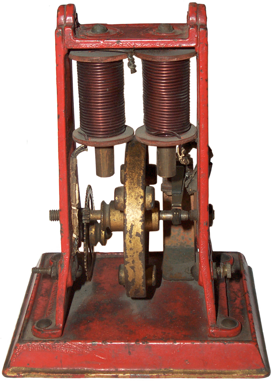
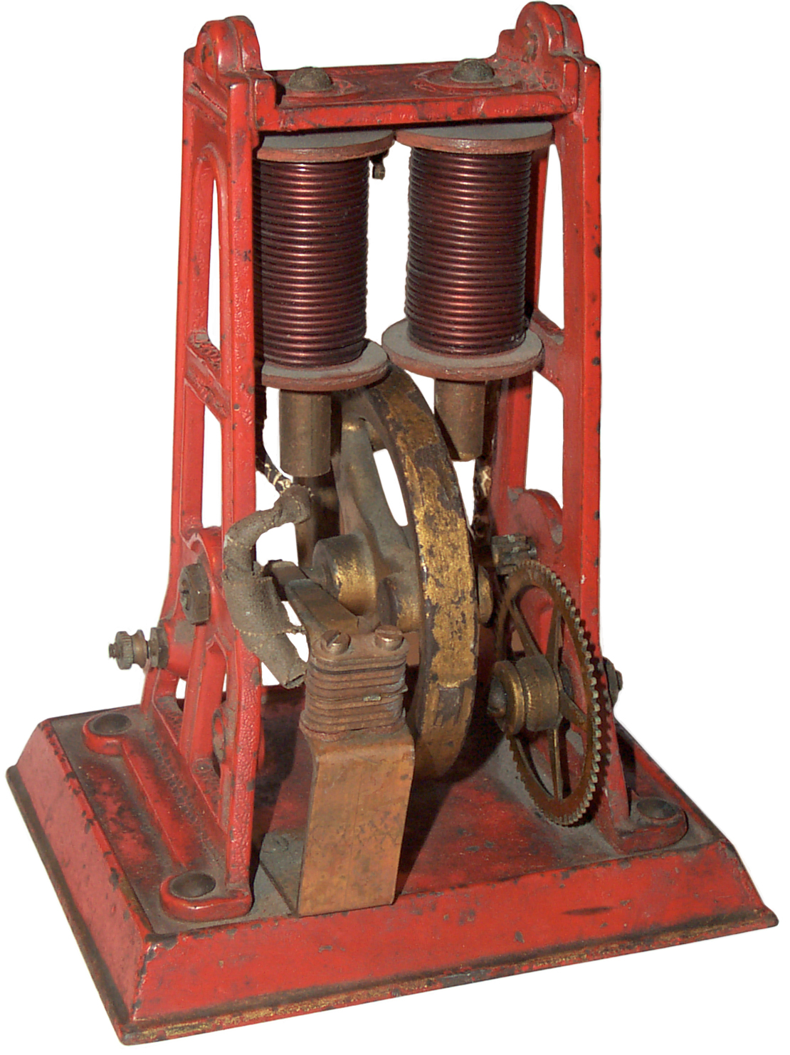
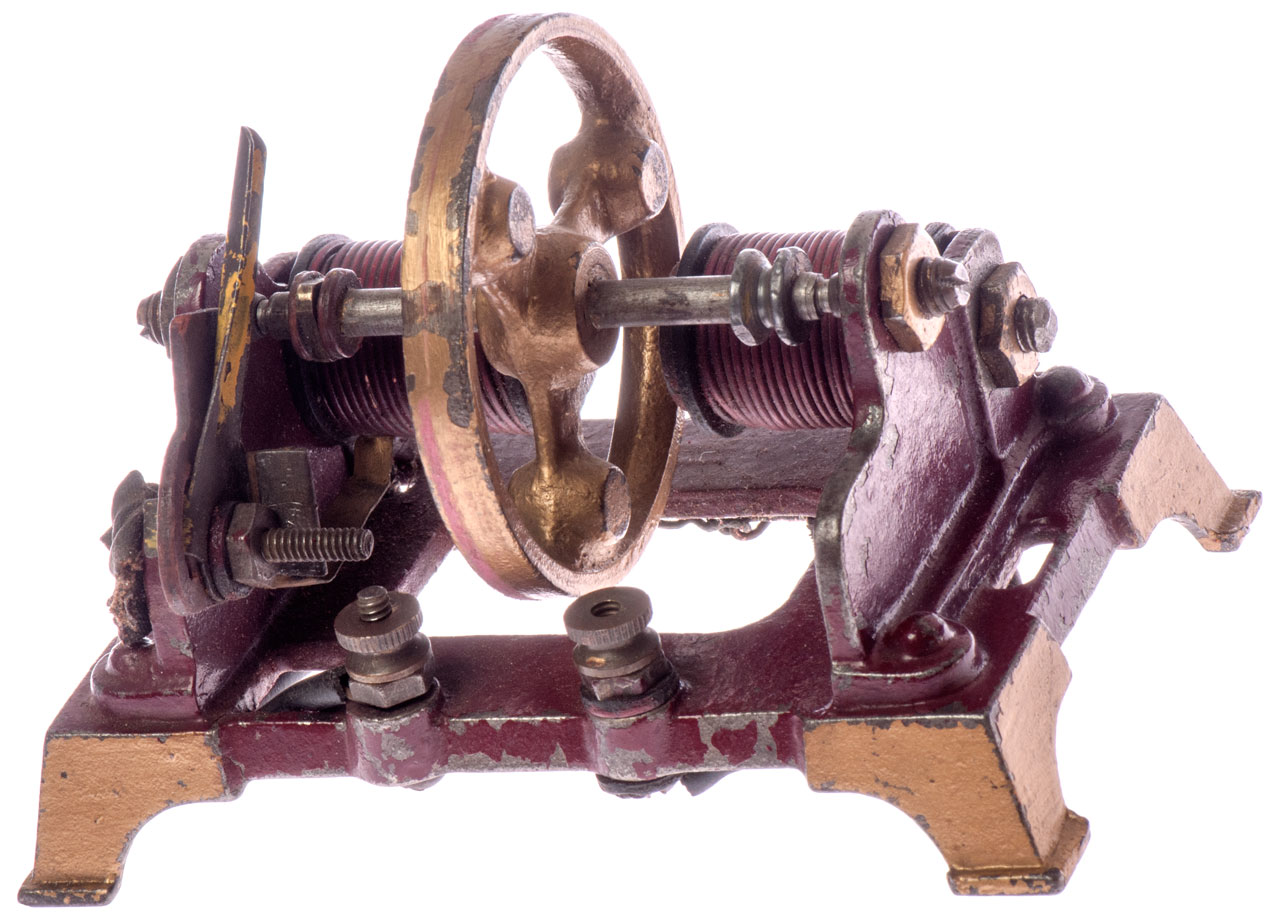
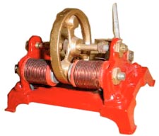
H-K Style L
This is a photo from eBay of what appears to be the
little brother to the above Toy Engine. The coils appear to be
shorter and use smaller wire then the above Toy Engine, but it's
hard to tell. This little brother engine was shown running
from a 6 volt battery.
Got the engine shown in Fig 1 and Fig 2 from M. A. 10 SPril
2017. But it turns out that the left coil in Fig 1 is open,
so need to be unwound to see what's wrong.
The first step is to remove the coil from the chassis and check
both leads hopefully the problem is with then rather than inside
the coil.
|
Fig 1
|
Fig 2
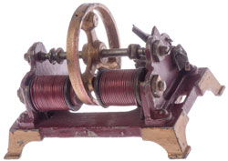 |
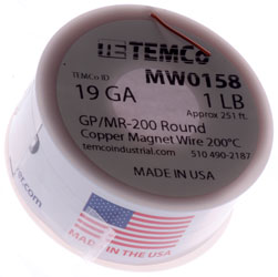
Fig 3 Coil ready for rewind
Less than 20' of 19 AWG

|
Fig 4 the 19 AWG wire has arrived.
|
21 Apr 2017
I've tried 2 times to wind a new coil and both times the
inner most turn shorts to the core.
The problem is that the right end in Fig 3 is not fixed but
instead depends on the nut to hold it in place. So
when the winding is finished and the nut and spacers removed
to allow installing on the motor frame a turn moves then
gets pinched.
Need to sleep on how to get around that.
|
|
|
Gilbert DC 3-pole Electro-magnetic
Machine - used with early Erector Sets & a larger small
appliance motor (maybe also Gilbert).
MESCO 1011 Toy Engine - works
like a steam engine
Toy Motor Kit & modern version as well
as Science First demonstartion motor -
Weeden DC 2-pole Electro-magnetic
Machine -
No. 6 Dry Cell -
and Flash Amps as measured with Pocket Ammeters
Links
Walter Anderson DIY
Old Model Company -
UK kits for early UK electric engines, one based on patent
10480 Improvement in Electro-magnetic Engines,
Charles G. Page, Jan 31, 1854, 310/21 - Beam Engine
Institute of
Chemistry - The heavy spoke
flywheel is 3 3/4” in diameter. The horizontal beam is 6 1/2” long.
- page also has photo of patent model
Back to Brooke's PRC68, Products for Sale, Telegraph, Leclanché
Battery, Electronics, Military Radio, Personal
Home page
< page created on 11 Aug 2007