|
|
GSQ-160 Overview
Key Components
BA-1549U BatteryADSID
MX-8846/GSQ-160 Detecting Transmitting Set Sub AssemblyA1 Sensor OscillatorAS-2542/GSQ-160 Antenna
A2 Supplemental Circuits
A3 2.5 MHz Signal Processor
A4 Secondary Processor
A5 Antenna Coupler
A6 Electrical Chassis
A7 Data TransmitterTC432 Code Plug
TC431 Encoder
TC-560 Transmitter
Atlas MMS Explosive Charge
Manuals
USQ-46 (USQ-46A) Radio Frequency Monitor Set WANTED TO BUYSimilar Equipment
TS-2963/USQ-46 Test Set
PP6446A/USQ-46 Power Supply
Battries for USQ-46 & TS-2963
ID-1721 Indicator WANTED TO BUY
PT1561 Code Plug Programmer
PT1586 Stack Tester
GATE General-Purpose Automatic Test Equipment
GSQ-154 Alarm Set, Anti Intrusion, Restricted Area - seperate web pageOther Manuals
Plant Antenna -
Contelco-Guard ME-400
TRC3- Photo -
PEWS - Photo of PEWS trasmitter Does this transmit a code that the USQ-46 receiver can understand?
GSS-26 -
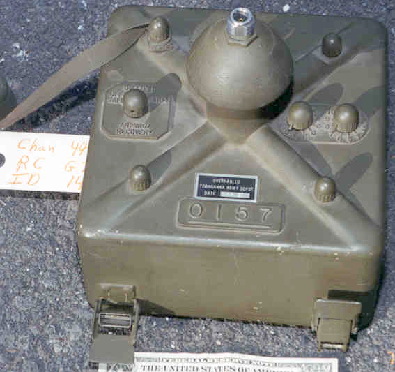
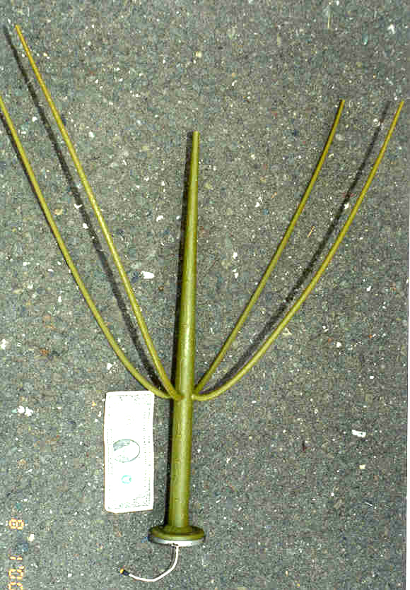
| Fig 1 top view |
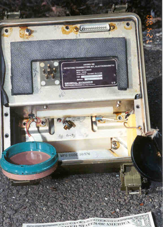
Fig 2 Illustration from manual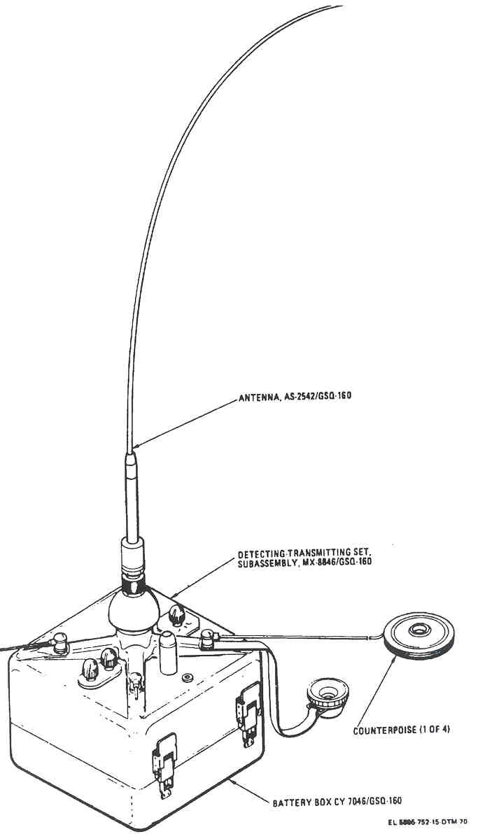 |
This is a battery powered set designed to be buried with the antenna and daylight sensor above ground. It detects changes in it's RF field at 60 & 57.5 MHz and will transmit an alarm around 168 MHz when it detects a change above some threshold. I think that not only will it detect people (or large animals) at about 120 feet and also vehicles at longer ranges but also any radio transmissions that might impair it's operation.
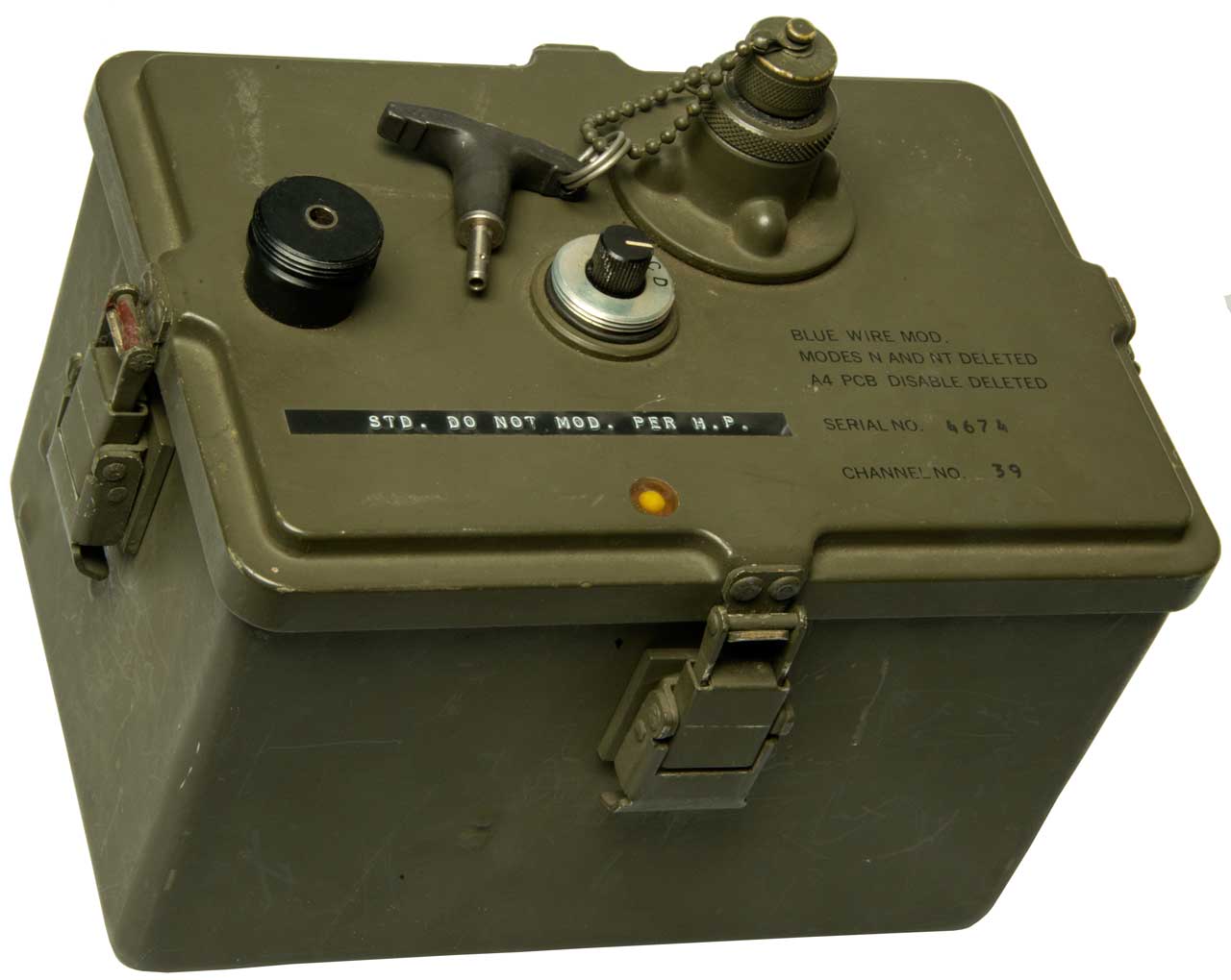
The date codes are for the early 1970's.There is a label on the top that says:
OVERHAULED The Surveillance Systems Directorate has jurisdiction for sensors. They are in Pennsylvania.
TOBYHANNA ARMY DEPOT
DATE MAR 81
Main Electronics sub-assembliesThe main electronics are contained in the top half of the case. The lower half holds the battery.BA-1549U Battery - Battery Box CY 7046/GSQ-160
The battery box is just the lower half of the GSQ-160 case.
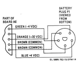
Has the following outputs:Since the batteries are hard to come by and the connector is not one I know, I plan to use some of the unused pins on the GATE DB25m connector for power. Both the GATE connector and Plug 1 are on the A6 motherboard.
- + 4 Volts
- - 4 Volts
- + 30 Volts
Pin 12 will be -4 VDC - to A6 Green wire
Pin 13 will be +4 VDC - to A6 Blue wire
Pin 25 will be +30 VDC - to A6 Orange wire
Fig 3 Battery Plug P1 schematic
MX-8846/GSQ-160 Detecting Transmitting Set Sub Assembly
The top half case has a 6 pin male plug that goes into the battery. There is a center pin with a flat and 6 smaller pins. Two of the smaller pins are ground contacts, but I have yet to determine which pin is what voltage. Drawing showing battery connector, tamper switch, GATE DB-25m. (You need the Free Volo or WHIP! Viewer from Autodesk).
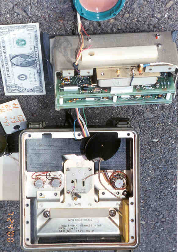
Fig 4 Bottom View
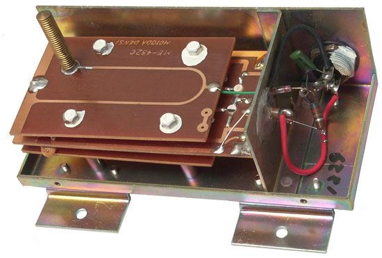
Fig 5 Chassis Removed
Fig 6
A1 Sensor Oscillator
This board contains two oscillators, one at 60 MHz and another at 57.5 MHz. They drive the antenna with about 1 milliwatt of power. These signals provide the EM field that detects changes in impedance.
This is NOT a seismic or magnetic detector, but rather an Electromagnetic filed based detector (Wiki).There is also a mixer that combines the transmitted and received signals to produce a 2.5 MHz output.
A2 Supplemental Circuits
There are functions for:
- daylight detection - either 24 hrs per day or night only operation
- tilt detection - destroy some electronics if unit is tilted or mechanically shocked while armed
- low battery detection - destroy some electronics if battery goes low
- battery case tamper switch - destroy some electronics if if battery case is opened
- Recovery Code switches - destroy some electronics if if wrong recovery code is set and unit is turned off
- + and - 2.8 VDC voltage regulator from + and - 4 V switched batt
- Disable pulse generator (3.5 Volts @ 30,000 Ergs) - to destroy A7 electronics
A3 2.5 MHz Signal Processor
This analog circuit does some primary signal processing on the 2.5 MHz signal.A4 Secondary Processor
Does log, filtering and anti-log operations and generates the alarm pulse.
A mute pulse also generated that is used to shut down the 57.5 & 60 MHz transmitter as well as stop signal processing during an alarm.A5 Antenna Coupler
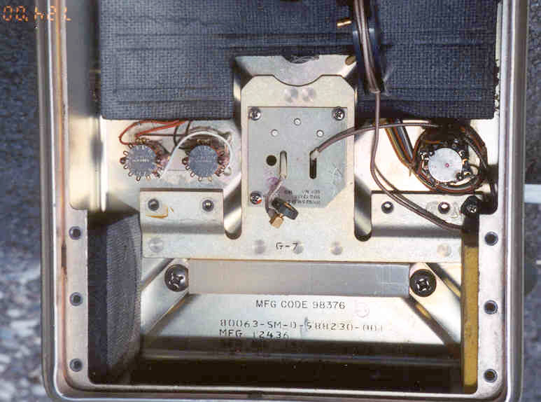
This is really a diplexer that allows the 60 & 57.5 MHz sensing RF go to the antenna and also allows the 162 - 174 MHz alarm transmission to also go to the antenna. A5 is part of the Plate with 3 screws
Note "G-7 Recovery code stenciled on bottom.
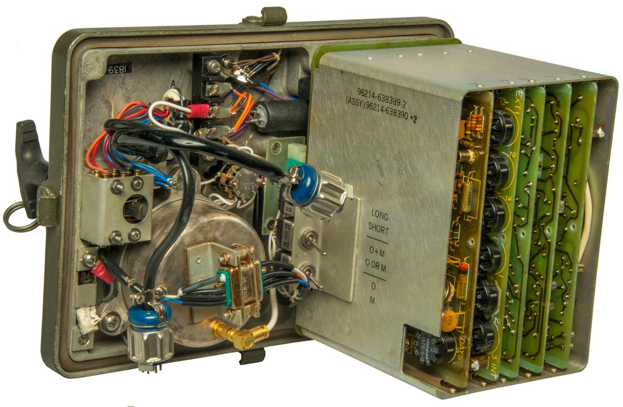
A6 Electrical Chassis
Contains the Off - Test - Arm switch, the daylight sensor, the two recovery code switches and a motherboard for the other modules to connect to each other.To remove chassis from top half:
There is also a DB-25m connector (A6J5) that is for use with the GATE test equipment. In the Photo you can see the tamper switch on the left, the cylindrical tilt switch "A5" and A6J5 connector.
- Remove coax connector "J1" that has a "wheel" attached with your fingers.
- Remove 4 slotted head screws in the bottom of compartment
- Remove 3 each #2Philips screws from top of compartment.
- Separate chassis from lid but be careful since they are still connected by man wires
- Confirm Recovery code by continuity test between Red and Brown wires going to Recovery Switches. Only when the correct code is set (G7 in this case) will there be continuity. In this case the white jumper wire goes from position 8 to position 8. If the switches are labeled as:
- 1 2 3 4 5 6 7 8 9 10 11 12
you can see that 8-8 corresponds to G-7.
- Set A B C D E F G H I J K
- Set 1 2 3 4 5 6 7 8 9 10 11
- CUT THE RED WIRE - in case you have a unit where the destruct pulse has not done it's damage, prevent damage from happening!
The Battery Connector has 6 male pins. The longer bigger center pin has a flat.
- 1 -2.8 VDC supply though 1 K Ohm
- 3 +2.8 VDC supply though 1 K Ohm
- 5 + 4.0 VDC supply though 1 K Ohm
- 7 Average Input Frequency
- 9 Alarm Inhibit
- 11 +30 VDC supply though 1 K Ohm
- 14 -4.0 VDC supply though 1 K Ohm
- 16, 19, 21 & 23 Common
- 18 Primary Output
- 20 Alarm Monitor
- 22 Detection Alarm Threshold
- 24 Log Compresson Output
When looking at this connector with the flat down:
- the pin directly above the center pin (12:00) is ground
- the pin at 2:30 is +4
- the pin at 5:00 is +30
- the pin at 7:00 is ground
- the pin at 9:30 is -4
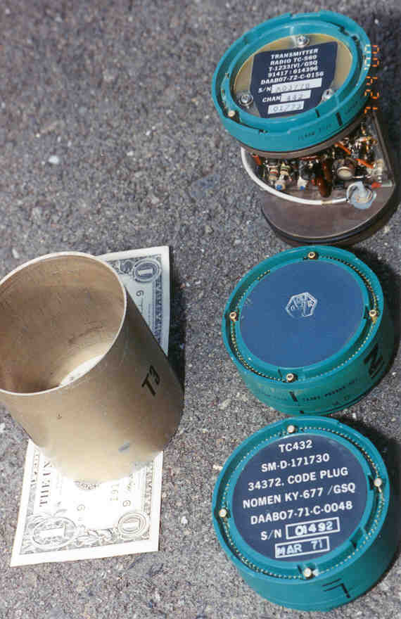
A7 Data Transmitter has 3 modules
Fig
This consists of three parts. These parts are not covered in the manuals for the AN/GSQ-160 and are used in other military equipment. These parts all are cylinders 2.75" in diameter and all have a common connector that is a ring with 92 pins and 4 coaxial connectors that are 90 degrees apart labeled A, B, C and D (not part of the pin numbering system). There are 4 versions of this connector here:
- TA383 both male and female pins and the module is just under an inch long
- TA385 has only male pins like on the transmitter Male End
- TA386 has Female pins and wires going to the GSQ-160 or other equipment
I think that this connector system was developed by Sandia. In the case of the TA385 combined male and female connector that all the pins go straight through (I will check this). If that's true then maybe you can install these 1" high modules in any order. They would take their power form known pins and send their outputs to pins that were only used for that purpose. More on this after some Ohm meter work. Table showing 92-pin wiring for the 3 cylinders.
25 Sep 2002 - I now think this is the same modular system used to build sonobuoys. The frequency range of the transmitter matches the assignments for sonobuoys.
14 April 2023 - After learning about Sonobuoys it think they need to be light weight, like Radiosondes, and the TCnnn series of modules are very heavy so would not be used in Sonobuoys because of their heavy weight. The ADSID is noticeably heavy.
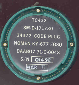
TC432 Code Plug
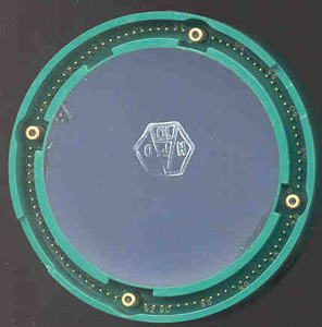
TC432 male end
TC432
SM-D-171730
34372, ODE PLUG
NOMEN KY-677 /GSQ
DAAB07-71-C-0048
S/N 01492
MAR 71
with hand written Label:
231 14 00 34
on the circumference of the cylinder
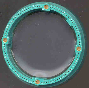
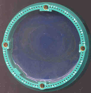
TC432 female end
This module connects to GSQ-160 mother board using the TA386 connector with 5 wires:
- Brown - Common Ground - TA386-47
- Red - Destruct Pulse - TA386-52
- Orange - +30 VDC switched power to cylinders - TS386-3
- Yellow - +6.3 VDC from cylinders - TA386-71
- Green - Alarm Call Up - TA386-36
This 0.95" tall module contains diode-resistor logic that can be programmed by fusing resistors. Each bit of data is determined by at least two resistors. If when reading the code either both resistors are there or both not there you know that the code is invalid.
There are 63 each 200 Ohm resistors in the module and the time to burn a module is 63 seconds. Maybe they allow 1 second for each resistor.
The type of data burned into the code plug is:
Details are available in the PT1561 Tech manual T.O. 31S9-4-18-1.
- RF Channel Number - 3 digits on the label, i.e. 231 in this case (but how does this correlate with the crystal # 442 and the Chan # 442 on the ID tag?)
- ID # - 14 in this case - the number that shows up on the USQ-46 or compatible receiver
- Audio Function - 00 and not applicable to this configuration
- Time & Gain - 34 in this case & also not applicable to this configuration
This is the module that customizes each equipment that uses the TXxxx cylindrical devices. They are custom burned for each serial number equipment and have individual ID labels.
The schematic appearing in Figure 6-7 T.O 31S9-4-18-1 does not show any connection with the Disable Pin #52.
TC431 Encoder
TC431 male end
TC431 female end
It does not have a printed label like the others. It is potted.
The Encoder reads the "Code Plug" data, checks it for validity and outputs a serial data stream that's either 18 or 24 bits long and at either 75 or 300 bits per second. The later two choices are determined by some of the bits in the "Code Plug". Zero volts is a space and 5.5 to 6.3 VDC is a mark.
Functions include:
- generating +6.3 VDC @ 16 ma max. for the other circuits from the +30 supply when there is an alarm condition.
- generating the serial data stream by reading the TC432 code plug. The levels are 0 to 1 Volt for space and 5 to 6 V for mark, but it's called "split phase" which means it's A.C. coupled to remove the DC component. This makes sense if it is used to drive a varactor diode that's across the crystal terminals in the transmitter.
- 5.5 VDC voltage regulator for it's own IC power
- It must also switch the +30 VDC on pin 3 of the 92 pin connector and connect it to pin 26 of the 92 pin connector to power the transmitter. This might be a relay or solid state switch. This is the only way that the transmitter module could get enough DC power to output 4 Watts of RF. The transmitter draws 430 ma max (13 Watts DC input max). The other + and - 4 V supplies are not connected to the cylinders and the 6.3 VDC supply has a very low current capability.
TC-560 Transmitter
TC-560 male end
TRANSMITTER
RADIO TC-560
T-1233(V)/GSQ
91417:614396
DAAB07-72-C-0156
S/N A03778
CHAN 442
01/73TC-560 female end
The contract number is different and the data codes are a couple of years different from the TC432 above. This is another indication that these cylindrical parts were (are?) used on a number of equipments. If the label and rubber gasket are removed the crystal can be seen to have a label of "442" indicating the channel number that matches this label as well as the tag attached to the outside of the GSQ-160.
This is the "T3" transmitter. There also are the "T1" (TC434) and T2 (TC516) available for use with the GSQ-160.
The frequency range is 162 to 174 MHz and the channel spacing is 18.75 KHz. The nominal output power is 4 watts.
To Open T3 DO NOT REMOVE ANY OF THE SCREWS! The Aluminum sleeve is held on by two o-rings. Just hold the green connector and turn the sleeve while pulling slightly away from the connector.
The following connector pins are used:
The Orange and white wires must be serial data in and DC power. The Orange wire is connected to what looks like a 1N400x diode wired as if the orange wire was carrying a positive voltage. So I will say that Pin 26 is + ?? VDC power for the transmitter and Pin 32 is the serial data our of the TC431 Encoder.
- 17 - black wire - Common Ground for input Printed Circuit Board
- B Coax - no connection in T3, just passes to the off center coax Conn. on Female End (test?)
- 26 - Orange to input PCB and series diode = +?? VDC power input
- 32 - White to input PCB right next to one of the crystal pins = serial data modulation. (0=space, +5.5 to 6.3 = mark).
- 47 - Black = Common Ground for output printed circuit
- 52 - Green - Disable wire to output PCB
The Disable pin A6P1 #52 is connected to a 0.15" diameter by 0.55" long white cylinder that has two wires coming out of each end. The green wire from Disable pin 52 goes to this component. It is marked:
ATLAS MMS
1.0-0-A
6.0 +/- ????
Explosive charge
and a small schematic diagram that indicates that the two leads on the green wire end go to a "resistor" with a dotted arrow to the other end where there is a normally closed (or normally open) switch. On my unit the switch seems to be open. Maybe this unit is OK or maybe it has been destroyed?
The two circuit boards of the T3 transmitter are screwed onto a steel plate with #1 Phillips screws and 1/4" across the flats nuts. The steel plate has two steel cylindrical end caps that hold the o-rings for the sleeve. All this steel is made from what appears to be a casting. It would be possible to place some explosive between the two printed circuit boards and destroy the boards, but I don't think that was done in this case. There are a number of wires soldered between the two boards so it would be difficult to remove them to inspect the back sides.
The Female end has two Mini 75 Ohm SMB Plugs. The center one is the transmitter output.
The off center one is not connected to anything inside the transmitter. It just connects to the "B" coax in the 92 pin connector. The purpose of this second coax line is for those systems that also have a receiver. A T/R Diode Switch TC530 (or TC620 for missiles) is connected between the stack end and the antenna.A Pasternack Ent. PE9619 Mini 75 Ohm SMB Jack to 75 Ohm BNC Female Adapter could be used for testing. The BNC side will mate to standard 50 Ohm BNC cables. Unfortunately they have a $100 per order min and $10 per line min.
AS-2542/GSQ-160 Antenna WANTED TO BUY
I would like to get one of these. It's a dual mode antenna with a type-N(m) connector at the base. The A5 Antenna Coupler drives either the outer conductor or the center conductor of the type-N(f) connector depending on the frequency and the antenna works in different modes for 57.5/60 MHz and for 168 MHz. It is designed with a slight bend so as to look like a plant.The top section is 32" and the bottom 14" for a total length of 46".
Manuals
Army TM 11-5840-352-14
Air Force TO 31S9-2GSQ-160-1
Electromagnetic Detecting-Transmitting Set AN/GSQ-160
and
Simulator Group OA-29/GSQ-160
(FSN 5840-168-7719)
March 1972
017470.pdf
Operating Instructions and direct support. Includes detailed functional description.TM 11-5840-352-24P
Detecting-Transmitting Set, Electromagnetic AN/GSQ-160
(NSN 5840-00-168-7719)
and
Simulator Group OH-29/GSQ-160
(NSN 6625-00-482-6150)
Current as of 1 February 1978
034516.pdf
Repair Parts designations and lists.
This is an acronym for Air-Delivered Seismic Intrusion Detector (Wiki). This unit can not be air delivered, but may be a support device, like a repeater?
See Sonobuoy Ref 11 Wiring Vietnam -
Display of A.D.S.I.D. (Air Delivered Seismic Intrusion Detector) Devices at U.S. Air Force Museum, 1:55 -
Overview
Locating this ADSID on this web page because it also contains the TXnnn llike modules.
In Fig 2 below the top cylinder is the battery also shown in Fig 4 as the left cylinder.
In Fig 4 is shown the top of the TC470A with knobs marked:
S3: OFF, 7, 14, 28, 45, OFF (maybe 7 days (1 week), 14 days (2 weeks), 28 days (4 weeks), 45 ( 1-1/2 months)?
S4: 1, 2, 3, 4, 5, 6 ?
There are three cylinders: Battery, TC470A Signal Processor & "4" Transmitter/Receiver "Destruct Removed". The transmitter programming plug is between the TC470A and destruct.
Under the end plate of the Signal Processor/Controller (Fig 6 below) there are two matching circuits going to the antenna connector, so maybe a diplexer allowing for both transmission and reception.
Fig 1
Fig 2 BNCm-Antenna
& Instructions
Fig 3
Fig 4
Fig 5
Fig 6 Signal Processor "4" shown
with cable to BNC antenna jack.
I'm placing this here because the batteries for this unit and the ADSID HIT Assembly above both use a battery in a custom aluminum housing that has a minature "D" connector.
I think DSID stands for Disposable Seismic Intrusion Detector. This is consistent with a custom battery that no one could replace.
Photos
Fig 1
Fig 2
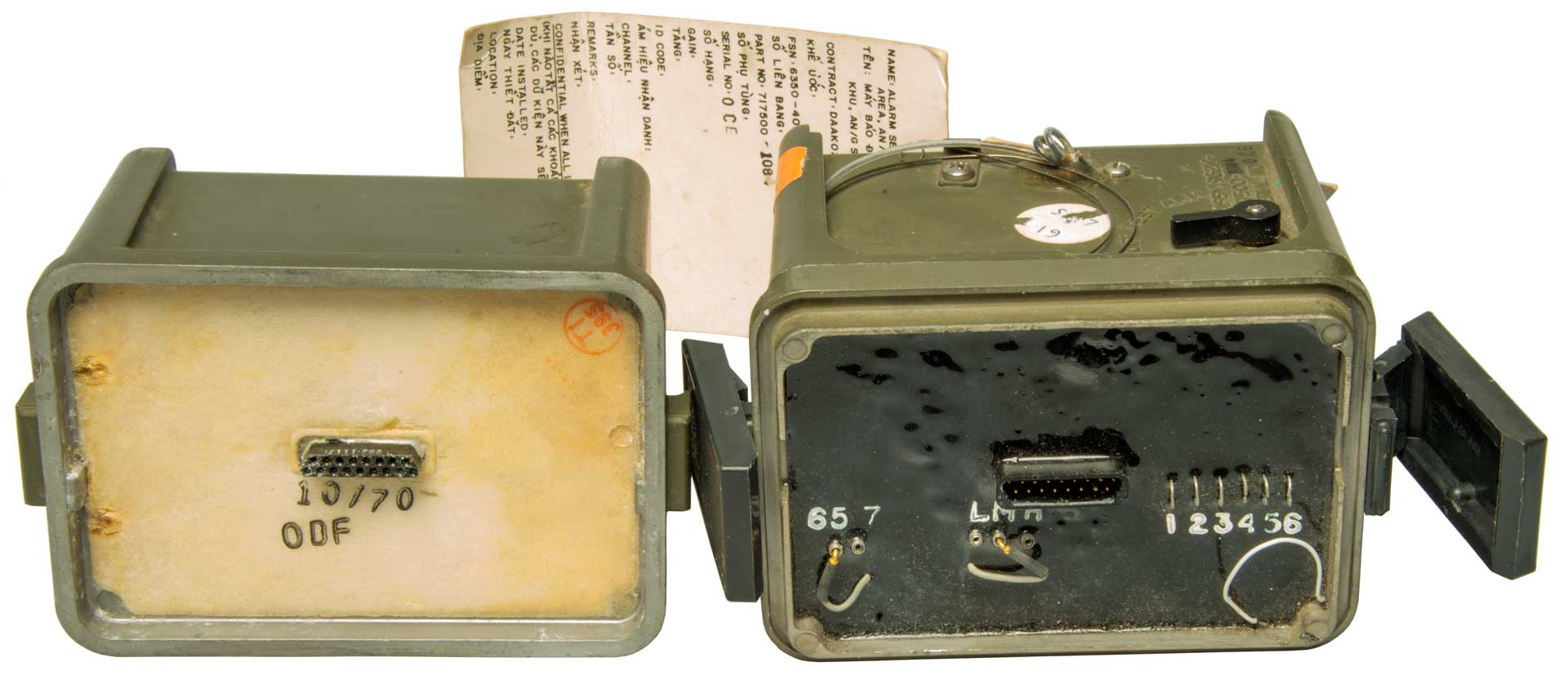
Labels
Name: Alarm Set, Anti-Intrusion, Restricted Area, AN/GSQ-159 (V) (DSID)
Contract: DAAk02-70-C-0566
FSN: 6330-402-2026
Part No. 717500-106
Serial No. OCE
Gain:
ID Code:
Channel:
Remarks:
Confidential When All Items are Filled in Below:
Date Installed:
Location:
Wehn filled in with date installed and location data, this tag contains information affecting the national defense of the United States within the meaning of the Espionage laws, Title 18, U.S.C., Section 783 and 784. The Transmission of the Revelation of it's contents in any manner to an unauthorized person is prohibited by law.
Excluded from automatic regrading DOD Dir. 5200.10 does not apply.
AN/GSQ-159(V) (DSID) Installation Instructions
1. Remove Identification Tag & Record Sensor Location
2.Implant Sensor and Erect Antenna
3. Turn Power Switch to Test
4. Check Operation with AN/USQ-46 or RF Indicator
5. Turn Power Switch To Arm
6. Complete Camouflage of the Sensor and General Area
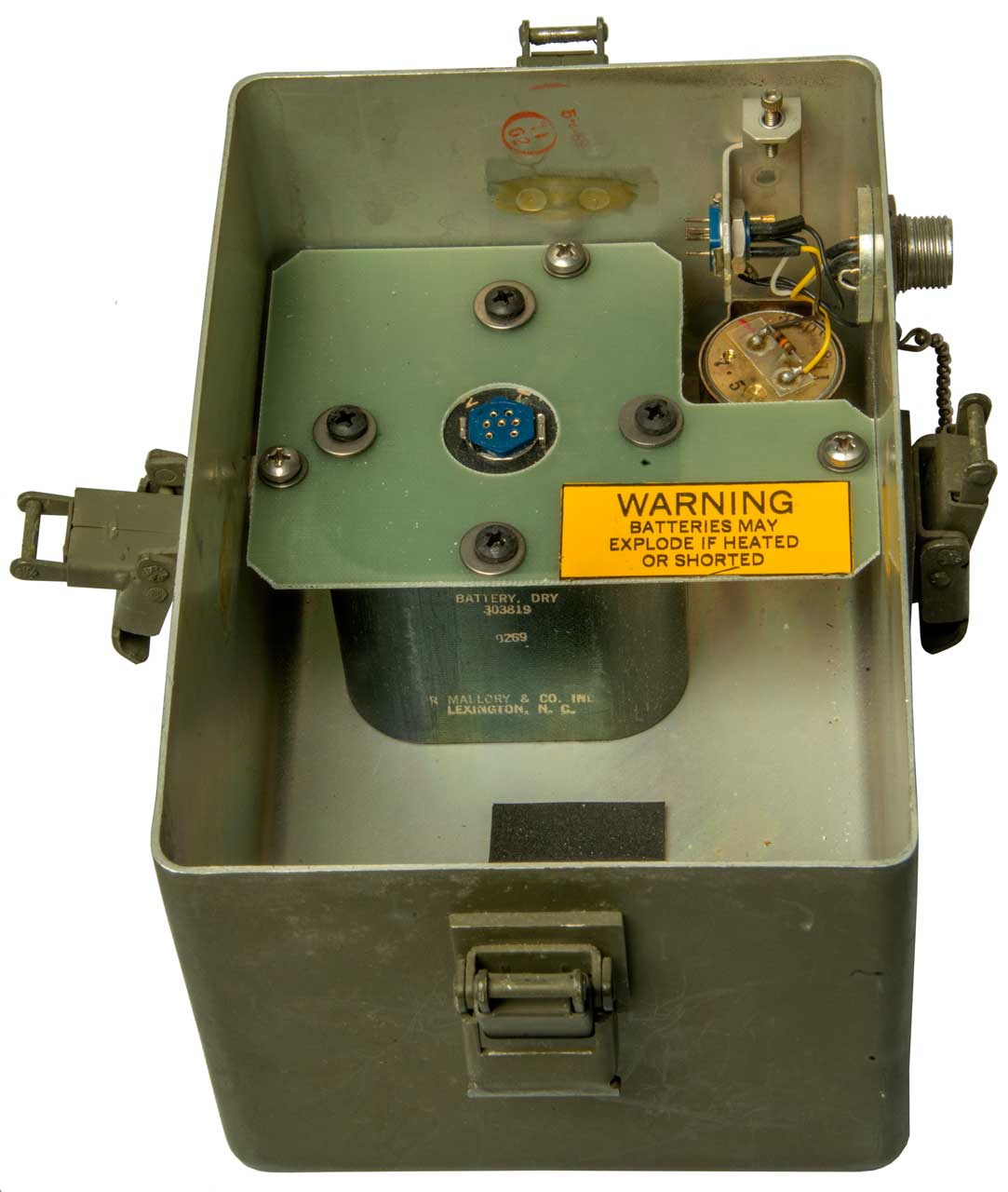
This was part of the package deal along with the GSQ-171, so I'm putting it here even though it does not use the TCnnn modules.
No identifying markings. The battery compartment seems to have a built-in "7.5" seismic sensor.
Fig 1
Fig 2 PL-259 Antenna connector.
Fig 3
Fig 4 Battery: Mallory 303819 (DC: 0269)
"7.5" Seismic Sensor
R1617/USQ-46 (USQ-46A) Radio Frequency Monitor Set
TS-2963/USQ-46 Test Set
PP6446A/USQ-46 Power Supply
ID-1721 Indicator WANTED TO BUY
PT1561 Code Plug Programmer
T.O. 31S9-4-18-1
TM 11-6625-2514-14-2
Code Plug Programmer Test Set
Model PT1561
Part No. 336467-000
F41608-71-C-0948
This copy is a reprint tht includes current changes 1 through 3.
15 February 1971
Change 1 10 April 1973
Air Force 7-8-73 - 250 Reprint
016407.pdfPT1586 Stack Tester
AF T.O. 31S9-4-20-1
System/Stack Tester
Model PT1586
Part No. 286823-000
F41608-71-C-0948
F41608-71-D-0973
This copy is a reprint that includes current changes 1 through 5.
15 February 1971
TM 11-6625-2514-14-1
The PT1585 is a tester for use with a stack of the 2.75" diameter components.
The MA31, MA33, MA37, MA124, MA133 (AUDET), MA134 (EDET), MA135 (AUDET), MA136(EDET), MA137(Sesmic), MA138(Seismic AUDET) , MA139(Seismic EDIT) sensors and MA56, MA87, MA88 EXRAY's or completely assembled sensors or EXRAY's can be tested. This includes the CADET family of sensors. Some of the sensors are:Hi-rise refers to a rocket powered stack.
- TC431 Encoder
- TC533DW - Timing and Destruct
- TC434 Transmitter
- TC517 Receiver
- TC534 Decoder
- TC447 short life battery
- TC438 battery
- TC516 Transmitter
- TC530 Diode Switch
- TC596 Receiver
- TC614 crimping tool
- TC619 Hi-rise Timing and Destruct
- TC620 Hi-rise Diode Switch
- TC662 - engine detector module
- TC665 assembly trough
- TC659, TC660 or TC668 - enable/disable module
MA31 is a Command Link (CL) sensor containing 9 modules
consists of: TC437, TC431, TC432, TC430, TC436, TC433, TC434, TC460MA125, MA135, MA137 and MA133 are ground CL sensors with 10 modules
MA124 and MA133 are CL hangup sensors with 8 modules
MA33 and MA37 are Non-CL sensors with 5 modules:: TC431, TC432, TC434 (less TC437)
MA134 (5 modules), MA136 (7 modules) and MA139 (7 modules) are NCL sensors
MA56, MA87 and MA88 EXRAY's are expendable relay sensors with 6 modulesThe L module may be the TC432 Code Plug
The T module is the Transmitter
The E module is the TC431 Encoder
order of remaining modules: E L Z J S R T V wires from the V module.GATE General-Purpose Automatic Test Equipment
This was a Generic Automatic Test Equipment system based on the HP 2116 computer (core memory), paper tape reader and a lot of equal vintage HP test equipment. In this way you could automatically measure common parameters like voltage, resistance, frequency, power, etc.using an adapter that connected the device under test with the test equipment. By measuring the voltages on the GATE connector you will be measuring Test Point voltages (or frequency, resistance, etc.).
All of the above Technical Manuals are available on line at LOGSA.
If you have either of the below manuals contact me.
TM 11-5985-385-14&P Title?
065241.pdf -classifiedTM 11-5821-356-23 RADIO SET AN/ARC-164 RADIO RECEIVER-TRANSMITTERS RT-1145F, RT-1167, RT-1167A, RT-1167B, RT-1167C, RT-1167G, RT-1167H, RT-1504, RT-1518, RT-1518A, RT-1518B, RT-1518C, AND RT-1614 RADIO SET CONTROLS C-9682B AND C-11721 ELECTRICAL EQUIPMENT MOUNTING BASES MT...
074680.pdf -classified
Rubber coated with "branches" that are not an active part of antenna.
Need to measure the VSWR to see if it would work on the GSQ-160.
DT-561(A)/GSQ hand-emplaced, magnetic detecting sensor.AN/PSR-1 Model X-150A - on my Sensors web page
DT-562(A)/GSQ. This is a hand-emplaced, SA classifying sensor. It detects targets and classifies them as unknown, wheeled vehicle, tracked vehicle, or personnel.
DT-565(A)/GSQ. This is a hand-emplaced, passive IR detecting sensor
Radio Repeater, RT-1175(A)/GSQ
Monitor/Programmer, AN/PSQ-7
Advanced Monitoring Display System . (AMDS)
Batteries. The sensors, repeaters, and M/P use either BA-5557/U lithium or AA alkaline or nicad
The REMBASS set uses the AN/GSQ-187 to relay data.
TRAINING EQUIPMENT
RO-376A-USQ Signal Data
Recorder
AN/USQ-46A
Portable Monitor
AN/GSQ-159
Disposable Seismic Intrusion Detector
AN/GSQ-154A Miniaturized
Seismic Intrusion Detector
DT-383/GSQ Audio
Add-on Unit
AN/GSQ-171
Directional Infrared Intrusion Detector
AN/GSQ-176(S) Air
Delivered Seismic Intrusion Detector (Short)
AN/GSQ-176(N) Air
Delivered Seismic Intrusion Detector (Normal)
AN/USQ-66(V) Battlefield Area
Surveillance System
TS-2963/USQ-46
Emission Generator
AN/GRQ-21
Expendable Relay
AN/GRQ-26
Receiver-Transmitter
AN/GXQ-257 Unattended
Ground Sensor Set
AN/MSC-77
Sensor Mobile Monitoring System
M1097 High Mobility
Multipurpose Wheeled Vehicle
AN/USQ-126 Sensor
Monitoring System
RO-630/USQ Signal
Data Recorder
SMS Antenna Group
SDR Remote Kit
Communications Group
RE-1162/U
Relay Assembly
Relay Unit
UHF Assembly
Battery Box
Relay
Assembly
Antenna
Support Kit
AN/USQ-121 Portable
Monitor
Test Set, TRSS
GSS-26(A) Alarm Set, Anti-Intrusion Restricted Area - After opening this hermetically sealed can I found no sensors. There are 3 double sided printed circuit boards, 1975 date codes, high Q analog caps and inductors and what may be IC type op-amps. I would say this is some type of analog processing circuit, maybe an "Audio" based alarm. There are 3 connectors, maybe Power, Microphone input and Connection to rest of alarm system?
TM 11-6350-200-10 is on the ETM page,
but is restricted.
Cites 28 patents:6816109 Method for automatic association of moving target indications from entities traveling along known route, Steven A. Schwartz, Northrop Grumman, 2004-11-09, - can be generalized to finding convoys, Hough transform (Wiki, 3069654), How invented,
Cited by 38 patents
3704764 Air deliverable seismic system, Harold B Henderson, TI, 1972-12-05, -
4492111 Rheological penetrometer, James L. Kirkland, 1985-01-08, - ground conditions such as soil or water and other vari ous fluids or liquids which may be examined or tested by the apparatus.
4630246 Seismic-acoustic low-flying aircraft detector, Robert J. Fogler, AF, 1986-12-16, - correlates seismic & acoustic to detect "under the radar" aircraft
4683474 Survivable ground base sensor, George W. Randig, AF, 1987-07-28, - radar system with each sub-array >=10 miles from each other to survive nukes, centered on North Dokota
4722282 Payload-carrying projectile, Reinhard Synofzik, Rolf Hellwig, Rheinmetall AG, 1988-02-02, - air dropped sensor
4818994 Transmitter with internal serial bus, Kelly M. Orth, Steven M. Quist, Roger L. Frick, Randy K. Paschke, Rosemount, 1989-04-04, - n industrial process control
5075857 Unmanned compliance monitoring device, Joseph S. Maresca, 1991-12-24, - "Unmanned compliance monitoring device, data communication network and transaction processing apparatus for monitoring earth tremors, collecting and reporting seismic data profiles and calculating an earthquake epicenter incorporating"
5339281 Compact deployable acoustic sensor, Patrenahalli M. Narendra, Russell D. Braunling, II William J. Wegerer, Jonathan C. Werder, Northrop Grumman Innovation Systems (Alliant Techsystems Inc), 1994-08-16, - acoustic target detection and classification
5432546 Weapon impact assessment system, Lee B. Cargill, Enel Co, 1995-07-11, - camera released from weapon trails it on tow line.
5554994 Self-surveying relative GPS (global positioning system) weapon guidance system, Arthur J. Schneider, Raytheon (Hughes), 1996-09-10, - looks like differential RTK GPS (Wiki)
5575438 Unmanned VTOL ground surveillance vehicle, Kevin P. McGonigle, John Ferraro, James P. Cycon, Raytheon Technologies (United Technologies), 1996-11-19, - flying saucer, counter rotating props inside donut, surveillance pod above.
5621669 Moisture sensor probe and control mechanism, Eyjolf S. Bjornsson, 1997-04-15, - modular moisture probes for large lawn sprinkler system
5662165 Production wells having permanent downhole formation evaluation sensors, Paulo Tubel, II Albert A. Mullins, Kevin Jones, Frank D. Richardson, Baker Hughes Holdings, 1997-09-02 - modular system for multiple oil wells
5730219 (similar to the above)
5812068 (similar to the above)
5841280 Apparatus and method for combined acoustic and seismoelectric logging measurements, Western Atlas Int, 1998-11-24, - modular oil well probe
5867257 Battlefield personnel threat detection system and operating method therefor, Robert R. Rice, Mark S. Zediker, McDonnell Douglas, 1999-02-02, - micro-Doppler LADAR, REmotely Monitored Sensors (REMS), unlike geophones & Goubau Lines (Wiki, 2685068, 2921277) which put soldiers at risk to install, this system looks toward the enemy but does not need to be installed in hostile areas.
5884867 Stabilizing apparatus, Tal Gordon, Dan Omry, Guidex Ltd, 1999-03-23, - a gimbal below a parachute stabilizes a hi res camera
5904210 Apparatus and method for detecting a location and an orientation of an underground boring tool, Gregory S Stump, Christopher T. Allen, Vermeer Mfg, 1999-05-18, - used to control a boring bit to tunnel under roadways &Etc.
6006338 Process transmitter communication circuit, Randy J. Longsdorf, Grant B. Edwards, Richard L. Nelson, David L. Pederson, Rosemount, 1999-12-21, - modular process monitoring
6056237 Sonotube compatible unmanned aerial vehicle and system, Richard L. K. Woodland, 2000-05-02, - UAV is generally comprised of modular Sections
6072524 Electronic observation post with communications relay, John E. Davis, Veron R. Creekmore, Boeing, 2000-06-06, - A SIRPS (Staring Infrared Panoramic Sensor) mounted on a Rogollo wing (Wiki) (B.C. or maybe a Kytoon (Wiki)
6127926 Intrusion sensing systems, David John Dando, 2000-10-03, - special radar to detect climbing on building scaffolds
6130642 Method and system to improve GPS navigation, Robert C. Woodall, Jr.Felipe A. Garcia, Navy, 2000-10-10, - "...provide a clandestine method and System that improves the navigation accuracy of GPS-guided vehicles while remaining dif ficult to detect or undetectable by enemy Surveillance." The pseudo-lite position is accurate to a few centimeters after sitting for an hour. An incoming munition activates the pseudo-lite which transmits a GPS signal which provides a much more accurate position that it can get from a satellite.
6164179 Submarine deployable vertical launch spar buoy, Martin Buffman, Navy, 2000-12-26, -
6260797 Transformable gun launched aero vehicle, Miles R. Palmer, SAIC, 2001-07-17, - modular air vehicle
6400647 Remote detection system, Gary B. Huntress, Navy, 2002-06-06, - can identify aircraft takeoff & landing (maybe aircraft type?)
5721712 Aircraft detection system, Kenneth M. LaPointe, Navy, 1998-02-24
4322828 Seismic aircraft maneuver classifier, Dave Hoff, Peter H. Vansloun, Northrop Grumman, 1982-03-30
4408533 Acoustic amplitude-threshold target ranging system, Owen, Suhler & Peters, AF, 1983-10-11 - for firing munitions at closest approach
5060206 Marine acoustic aerobuoy and method of operation, DeMetz, Honeywell, 1991-10-22 - Uses Helmholtz resonator as part of microphone - describes prior art patents. HRfreq(Hz) = (RPM *No. of prop blades)/60
4533945 Process and arrangement for aerial observation and/or communication for a submerged submarine
3258595 Remotely operated self-powered observation device including remotely controllable visual scanning means
3651286 Lavalier microphone assembly protected against friction noises
4189786 Radio buoy assembly
4203109 Submarine communication system
3999183 Floatable radio antenna
5978313 Time synchronization for seismic exploration system, Harold L. Longaker, Trimble, 1999-11-02
6898378 Shock-resistant backplane utilizing infrared communication scheme with electrical interface for embedded systems, Shannon M. Nelson, Stuart J. Collar, Mark D. Hischke, Northrop Grumman, 2005-05-24 - maybe a way to eliminate the ring connector?
Mike Murphy Surplus - my source for
much of the above
Fair Radio Sales - also had some printed
manuals that were not on LOGSA
for info on using LOGSA see my manuals
page
Brooke's PRC68 . alphanumeric index to web pages, Products for Sale, Contact
[an error occurred while processing this directive] page created 22 July
2000.


