Acoubuoy, Spikebuoy, Muscle Shoals and Igloo White by Chris Jeppeson - a lot of info on how the electronic battlefield worked in Viet Nam. The early air dropped seismic sensors were based on sonobouys with the hydrophone replaced by a geophone. There were constantly aircraft flying, acting as relay stations to pickup the sensor signals. Since the sensor transmitters were low power (2 Watts typical) they were hard to detect on the ground, but had a long range to aircraft. This is why they operate in the sonobouy 162 to 174 MHz frequency range.
See: The War against Trucks, Aerial Interdiction in Southern Laos 1968 - 1972, Nalty, (WarAgainstTrucks.pdf)
R-1170/ARR-52A Radio receiver, Sonobouy, 162.5-173.5 MHz, AM, FM and video 31 crystal channels, IF 26 MHz and 5 MHz, 18 VDC. This is a group of 4 receivers, so 4 different frequencies can be monitored at the same time.
eBay ARR-52 Sonobuoy photos R-1170 receivers, AM-2376, C-4405? 4 Chan control box, Top of Control BoxOther sensors transmitted in the aircraft VHF AM frequency range of 100 to 150 MHz. There were ground based receivers for both frequency ranges. The RC-3/3A was a small receiver for use with the TRC-3/3A sensors.
Were designed and produced by Resdel Engineering, Pasadena CA, starting about 1969.
The USQ46 extensively used CMOS digital circuits. At the time the program consumed about 80% of the entire RCA production of what was then
called COSMOS IC's.
Also see Sonobuoy\Ref 72.
|
|
| Left
digit much dimmer than right digit in test mode |
257477BA battery
adapter works |
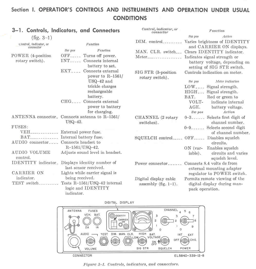
There are three versions USQ-42 (5820-791-5234), USQ-42A (5280-134-0572) and USQ42B. It is a channelized R1561 receiver that covers 161.500 MHz (chan 00) to 175.750 MHz (chan 39). This narrow band FM receiver picks up digital signals from sensors and indicates the sensor number from 00 to 99. It can use either the BA-386/PRC-25 or the BA-4386/PRC-25 dry battery or a rechargeable battery pack. I have the manual, but don't know about the sensors it works with. Channel numbers 0 to 39 are supported: 0 = 161.500, 1 = 162.250, 2 = 163.000, 39 = 175.750
This is the Navy sonobuoy band.
Components:
R-1561/USQ-42(_/A/B) Monitor, Radio Frequency
CW-1033/USQ-42 Bag, Cotton Duck
AB-1093/USQ-42 Base, Antenna (has adjustable length)
AS-2280/USQ-42 Antenna (can be used w/o base when back pack is used)
H-139 Headset
Digital Display cable assy (remotes the ID display when back pack is used)
ST-158/USQ-42 Harness, Electrical Equip. (back back ) - probably very similar to the ST-138 Harness used with the PRC-25 radio.
See my Sonobuoy page USQ-42 info
TM 11-5840-339-12 Operator and Organizational Maintenance Manual, April 1968-Operation Front Panel dwg & Table
eBay Front Photo R1617A/USQ-46 -
eBay Side Photo R1617A/USQ-46-
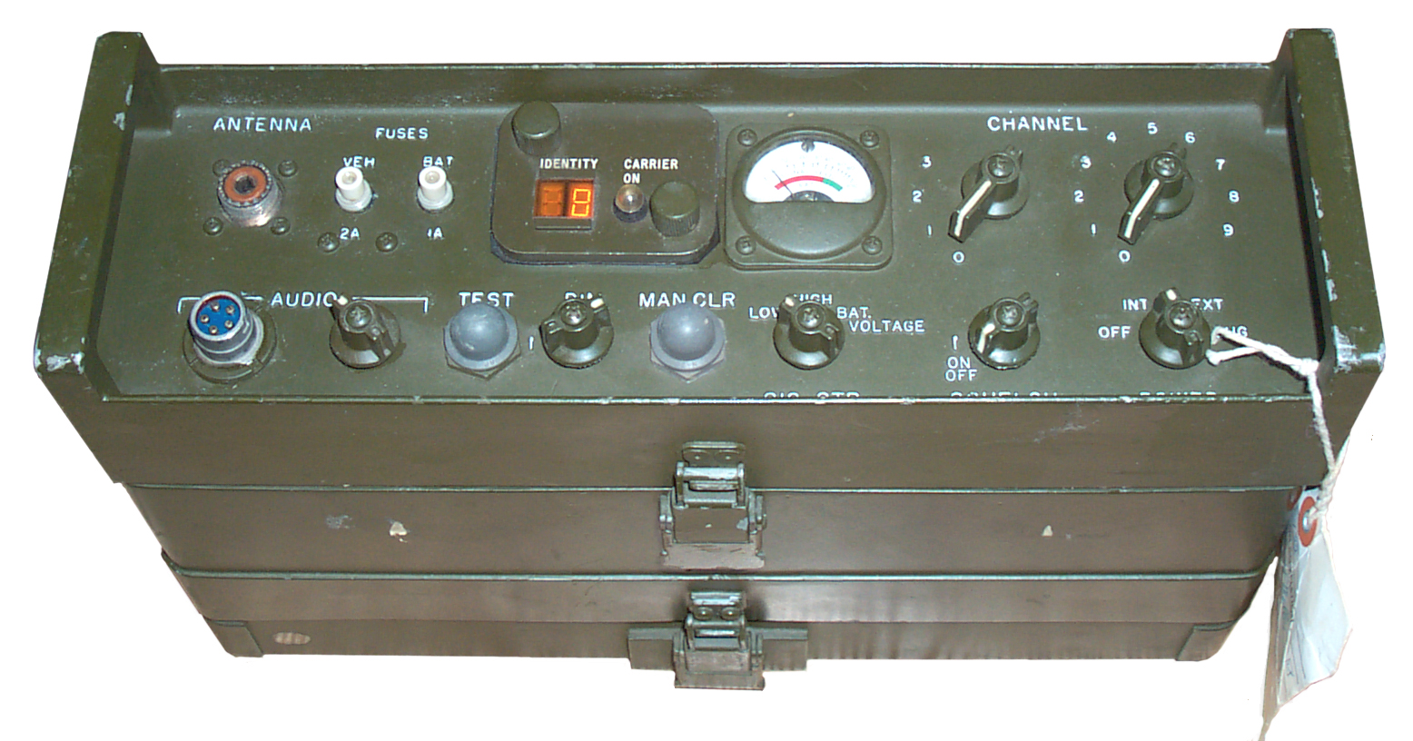
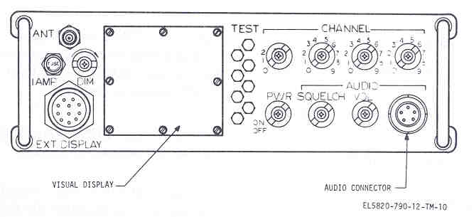
R1617/USQ-46(_/A) receiver
Decodes the 18 bit data word and lights a lamp to indicate which sensor is being received.
For those sensors that have audio output (few do) you can hear the audio.
For those sensors that send a 24 bit data word you need the IP-1721 to display the additional data.If the received frequency is below 162.000 MHz then the Freq_MHz = 145.525 + <chan#> * 0.00625,
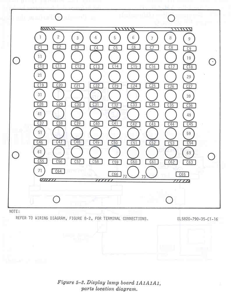
if the frequency is equal or greater than 162.000 then Freq_MHz = 162.000 + <chan#> * 0.00625.Has 66 Lamps that are numbered 1 through 71 (no lamps numbered zero, 10, 20, 30, 40, 50, 60 or 70) on front panel. The test switches to the right of the display turn all the lamps in the row to the left of the button and the "DIM" control will change the brightness during operation and test.
The "A" version replaces the RC timing circuits with digital timing circuits to decode the data. Because of the possibility of an explosion due to hydrogen out gassing from the battery both the radio and battery compartment of later units have a vent.
External Display Connector 1A1A1-J1 for the ID-1721
1A1A13 is the Display Buffer. It looks like the data on the external display connector has already been decoded from serial to parallel. There may be one bit on each of some number of pins as TTL data? The ID-1721 would still need to convert the binary value into a some kind of digital display.
- A - 1A1A13-J2#8
- B - 1A1A13-J2#2
- C - 1A1A13-J2#3
- D - 1A1A13-J2#4
- E - 1A1A13-J2#5
- F - 1A1A13-J2#6
- G - 1A1A13-J2#7
- H - 1A1A13-J2#16
- J - 1A1A13-J2#17
- K - 1A1A13-J2#18
- L - 1A1A13-J2#19
- M - 1A1A13-J2#20
- N - 1A1A13-J2#21
- P - 1A1A13-J2#22
- R - 1A1A13-J2#23
- S - Shield - 1A1A7-J3#shield
- T - 1A1-P18 = 1A1A7-J3hot
- V - 1A1A1-S13-A2 (POWER SW)
- W - 1A1A1-E1?
- X - 1A1A1-E1?
- Y - 1A1A1-E1?
- Z - 1A1-P1-5 = 1A2-J1-5 = +27VDC input
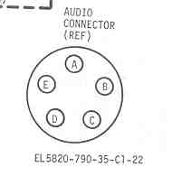
H-251/U headset connector (U-229 Pin Out)
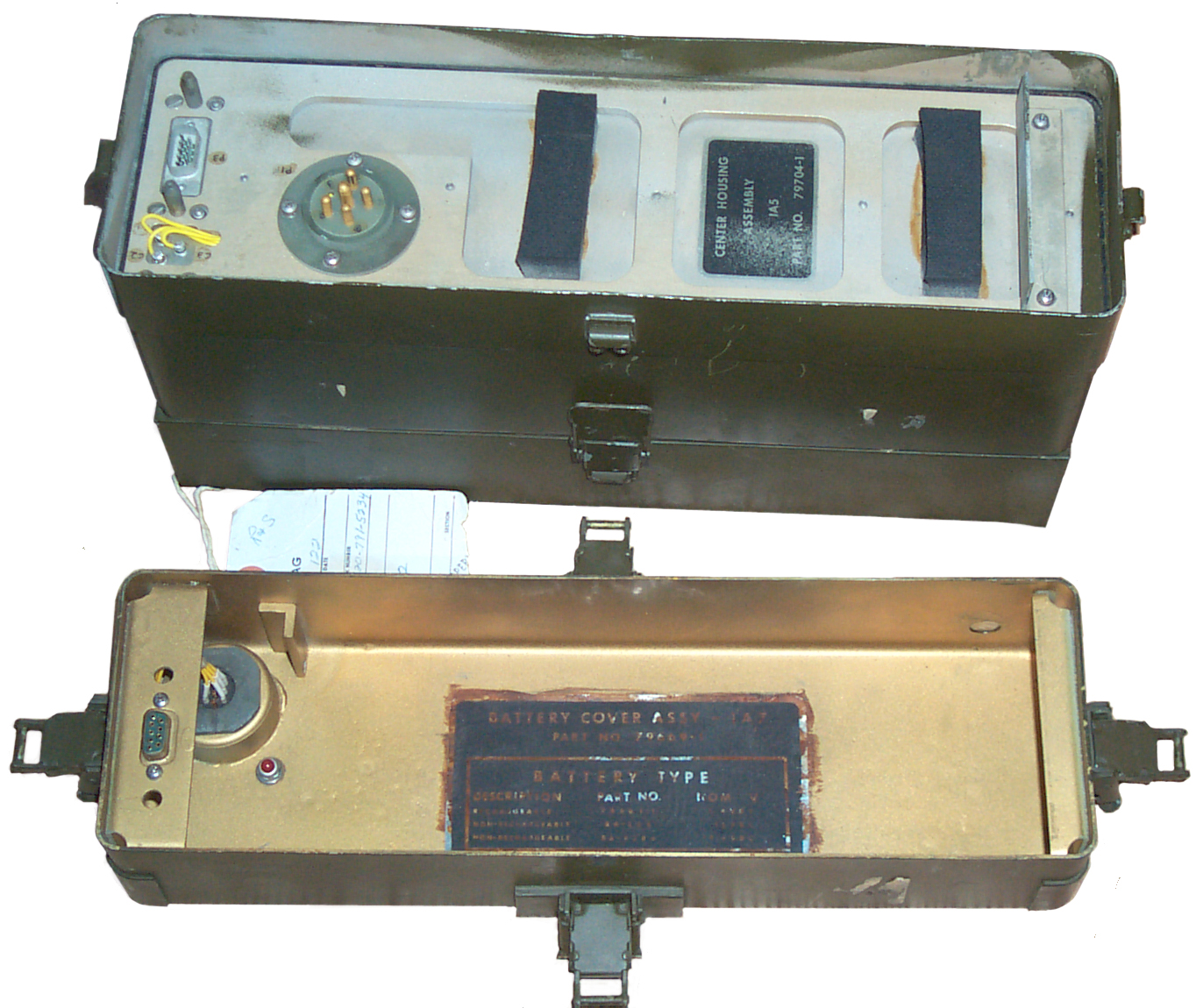
On the back is the battery/power supply connector.
- A - Gnd
- B - Audio
- C - Analog
- D - nc
- E - nc
The set can be powered by supplying + to pin B and - to pin A. At 10 volts input the low battery light should be on and at 11.0 the low batt light will go off.
For normal operation the voltage should be 12.0 VDC.TM 11-5820-790-12 (?availability)
TM 11-5820-790-12 (have hard copy)
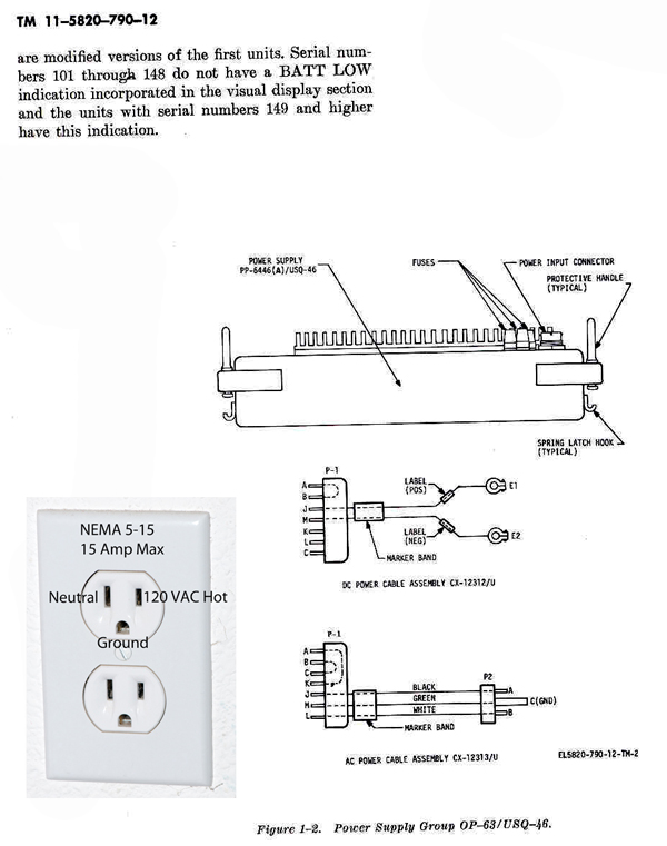
TM 11-5820-790-34 (have hard copy)PP-6446A/USQ-46 Power Supply
Uses the PP6446A/USQ-46 Power Supply, BB-586/U rechargable or BA-3386/U primary battery.
These battries also work in the: GRA-114, KY-38, KY-65, PPS-15, PRC-25, PRC-74, PRC-77, PRD-10, PRD-11, PSN-6, URR-69, USA-32, USQ-46
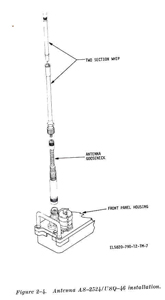
AS-2524/USQ-46 Whip Antenna WANTED TO BUY
AS-2549 antenna (and it's TM 11-5895-750-12) WANTED TO BUY
The short whip can be used by itself if the radio is being carried and it's front panel is facing up and they both can be used for fixed or vehicle installations where the radio is horizontal.Mount
MT-4261/USQ-46 is used to mount radio on the passenger side rear fender well of an M-151.
The CX-12312/U 6.5 foot long DC power cable is wired direct to the battery in this case.Headset
H-251/U Headset is used for hearing the audio.Bag
CW-1100/USQ-46 Bag, Cloth - to carry the ant. headset, battery BA-4386, lamp removal tool, operator's manualLamp Removal Tool
part no. 805580-1 Tool, removal Resdel - lamp removal tool.
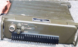
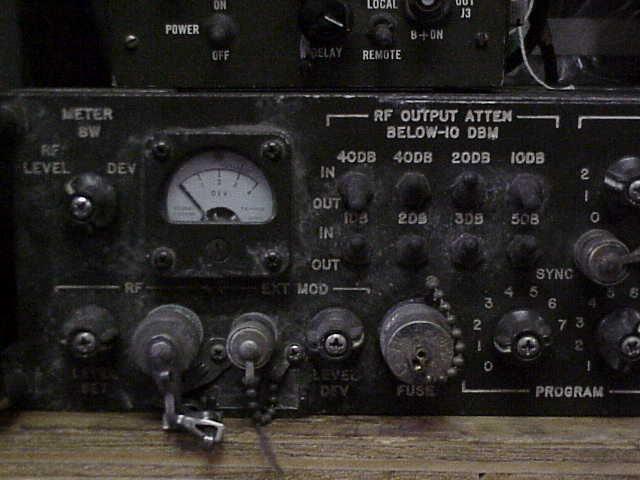
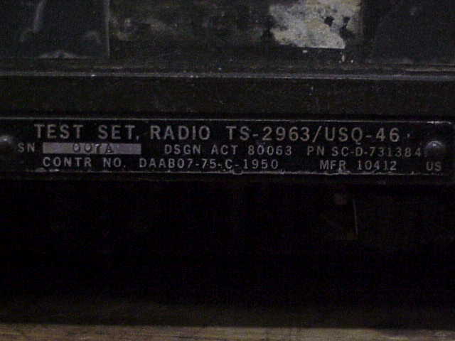
TS-2963/USQ-46 Test Set (Front Panel photo)
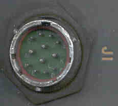
Used to test the USQ-46 or USQ-46A Radio Frequency Monitor and to test sensor stacks that have receivers and decoders. For the latter application in the field the same PP6446A/USQ-46 Power Supply (Rear Photo) is used for either the TS-2963 or USQ-46. The 6-pin battery connector (Photo J2) looks the same as the connector for the GSQ-160 BA-1549U Battery but the voltages are not the same.Also for field use to send control signals to sensor stacks that have receivers and decoders. This is why the TS-2963 is packaged as a field equipment and uses the same power supply and/or batteries as the USQ-46. If the AS-2524/USQ-46 & AS-2549/USQ-46 Antenna combination has a type-N connector that would be the logical choice for this application. Maybe no antenna is used and a direct connection is made to the sensor?
The OQ-60 Test Set consists of the:
The Test Set will exercise all RF channels and message formats that the USQ-46 or USQ-46A is capable of processing. The output frequency range is 160 to 176 MHz in 2520 channels with 6.25 kHz spacing. Output Freq (MHz) = 162.0 MHz + (Chan #) * 0.00625 MHz (see USQ-46 above for more on channel numbers)
- TS-2963/USQ-46 Radio Test Set
- PP6446A/USQ-46 Power Supply
+12 VDC regulated output- CX-12313/U AC Power Cable
- CG-3628/U RF Output cable
The data word consists of:
This means an overall word length of either 18 or 24 bits.
- 8 bit preamble (that is all zeros)
- 10 (short) or 16 (long) data bits made up of:
- bit # 1 = Sync bit that is always 1
- bit #2&3 = message type (type 1&4 short, 2&3 are long)
- bit# 4,5,6,7,8,&9 = Address/ID (64 possible)
- bit# 10 = Address parity (1 ID has even numberof bits)
- bit# 11,12,13,14,15 & 16 = message bits used only for long word and in the receiver are not processed but routed to the connector for the ID-1721 that reads these 6 bits.
If the rear case is removed (4 screws into back of front panel) there is a DB9 connector that routs the DC power from the bottom of the case to the electronics. More on it's pin out later.TM 11-6625-2578-12
Radio Test Set Group
OQ-60/USQ-46
October 1972
016118.pdf
Contains Operation information for the Test SetTM 11-6625-2578-34
Radio Test Set GroupOQ-60/USQ-46
April 1973
016120.pdf
Contains a detailed description of how the TS-2963 works.
This includes a good description of the data word that is sent by a sensor.
Also troubleshooting info for the test set.Photo of Left Side, Right Side, Name Plate of TS-2963 (from Mike Murphy Surplus)
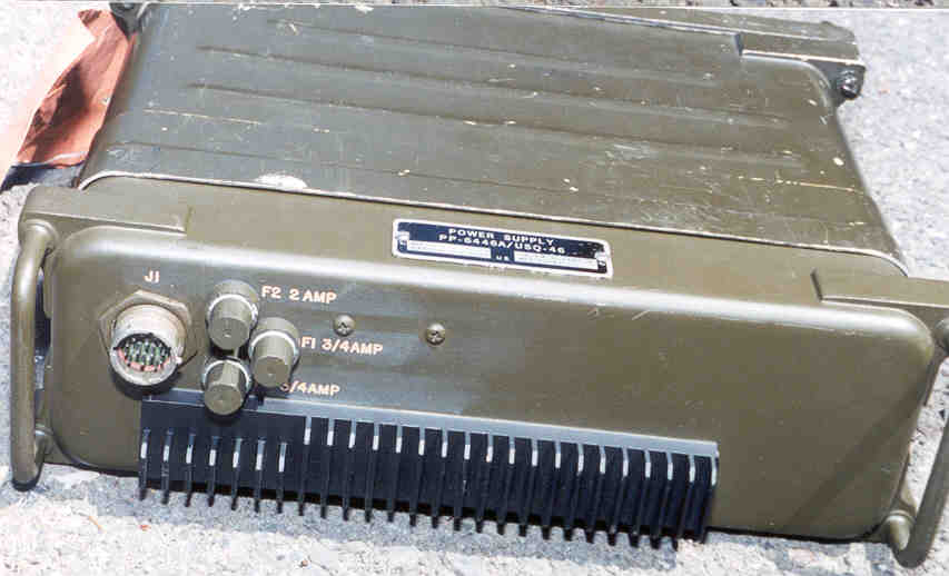
Test Set PP6446A/USQ-46 Power Supply
Used on the TS-2963 Test Set and the USQ-46 radio.
This is really 2 separate supplies. First is an transformer full wave rectifier with 2 stages of LC filtering that outputs about 30 VDC (J1-B).
The Second Supply takes in +22 to + 33 VDC (J1-A) and outputs a regulated +27 (J2-E) and +12 VDC (J2-B).
The Hot input (J-J) is passed to (J2-C) the front panel of the radio or test set and it's ON-OFF switch returns (J2-D) the switched power to J1-A where it is jumpered to the input of the 115 VAC supply (J1-J) or the 27 VDC supply (J1-A) This is shown on the Drawing. with the two supply cables.Fuse 1 and Fuse 2 ( 0.75 A Fast-blo) are on the 115 VAC input. Fuse 3 (2A Fast-Blo) is on the 27 VDC input.
Theoretically you could connect the jumper for 115VAC operation (J1-B feeding J1-A) and at the same time connect a charging regulator from J1-B to Battery Positive and Battery Negative to Ground ( J1-L).
Schematic showing input plug wiring for either 22 to 33 VDC in or 100 to 132 VAC @ 50 - 60 Hz or 400 Hz Input
Drawing of rear showing the multipin connector. (PP6446.dwf)
TM 11-6625-2578-34 "Radio Test Set GroupOQ-60/USQ-46" has information on the PP6446A Power Supply.
(Rear Photo) Scan of J1 Power input connector http://www.fciconnect.com
Nov 2011 - the J1 mating connector needed to make an AC or DC input cable is: PT06A 14-12S
CX-12313/U 115 AC Power Cable FSN 5995-177-3699
CX-12312/U 27VDC Power Cable
Cable Wiring from TM 115280-790-12
AC/DC Input Connector
Pin
AC
DC
A
Switched
AC Hot
DC +
A, K
A, B
B
DC Reg In
B, C
C
Raw +35VDC
B, C
J
AC Hot
DC +
In
In
K
A, K
L
AC Neut
In
M
AC Gnd
DC Gnd
Gnd
Gnd
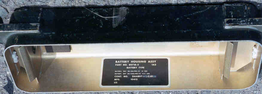
Battries for USQ-46 & TS-2963
- Battery Housing Part No. 80718-3 1A3 (Photo) has the following on the label:
Battery Dry BA-386/PRC-25 Alkaline D cells, 15AH A1=3V, A2=15V NSN: 6135-00-926-8322, Photo
Battery Dry BA-4386/PRC-25
- BB586U listed as a rechargeable battery for the PRC-25 - NSN: 6140-01-0984-1460
- BA3386/PRC77 Alkaline 15AH 15V NSN: 6135-00120-1016
- BA4386 Magnesium
- BA5598/U LiSO2 - Fair Radio a pair for $6.50 (July 2000) two of these fit in the battery box, one active and one spare.
- 257477BA Battery Adapter - holds 10 each "D" flashlight batteries.
ID-1721 Indicator WANTED TO BUY Contact
This box decodes the final 8 bits of the data word. The USQ-46 decodes the message type and ID.
The ID-1721 decodes the data bits. It looks like the serial data bits are converted into parallel bits in the USQ-46 receiver.
The ID-1721 then just needs to display them in some digital format.
They may also be sent to some type of recorder, in this case you would want to also know the ID and data so maybe that's why so many pins on the connector.
The ID-1721 may also display both the ID and data?
Brooke's Home Page Brooke's Military Information page -
mailto:brooke@pacific.net
[an error occurred while processing this directive] page created 7 Aug 2000.