Huntron Tracker
NSN 6625-01-115-0395© Brooke Clarke 2004
 |
 |
| 1005B
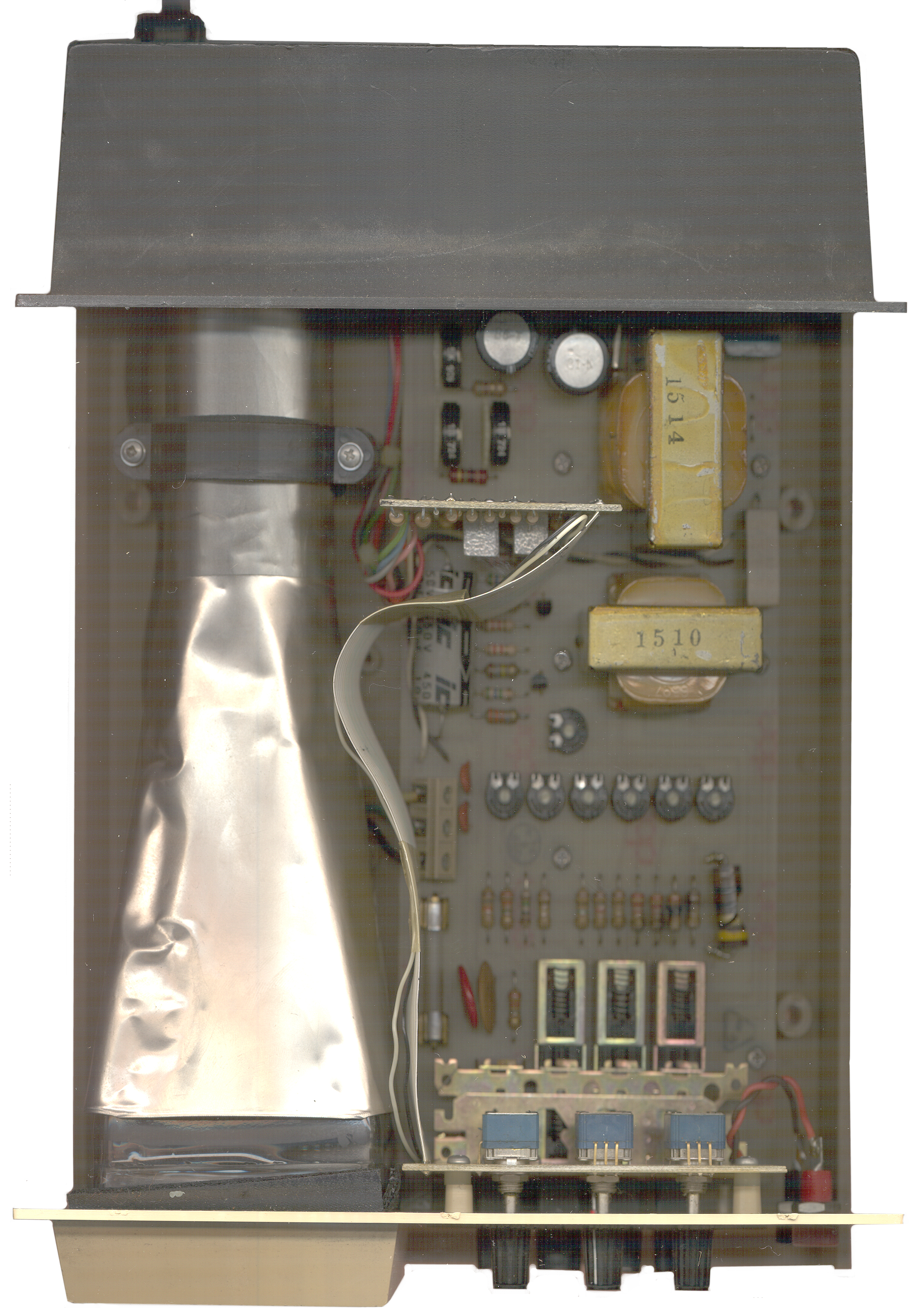
Front
with top cover removed |
Top
showing
blown 10 Ohm & other blown resistors |
Background
The Huntron Tracker series of
in-circuit component testers are specialized curve
tracers. You
could get the basic I-V plot for a component using a standard
semiconductor curve tracer. The Huntron units add
special
features designed to make their use for in-circuit testing
more
productive. Later models have provision for two unknown
devices,
a reference device and the device under test. Their
curves can be
shown using alternate sweeps thus overlaying one with the
other to make
it easier to see any differences.
HTR 1005B
The case is a stock Pac-Tec but Huntron has made a custom front panel and there's an extension box out the back to allow for a larger mother board.
HTR 1005B
| Range | Vp | Vrms | mArms |
| High | 60 | 42.43 | 0.6 |
| Medium | 20 | 14.14 | 0.6 |
| Low | 10 | 7.07 | 135 |
The case is a stock Pac-Tec but Huntron has made a custom front panel and there's an extension box out the back to allow for a larger mother board.
What goes Wrong
A first look shows that a 5 or
10 Watt
10 Ohm resistor is blown into three parts, the loose one was
ratteling
inside and looking for the rattle lead to the blown 10 Ohm
resistor. There are some nearby resistors that also
appear so
dark the color codes cna not be read. It sure would be
good to
have a schematic to see where these resistors are and what
would cause
them to blow so the real problem can be fixed.
The patent "4074195 Semiconductor Tester" is probably for the first Huntron Trackers in the 1000 series. The circuit diagram shows that there's no way to blow the only 10 Ohm resistor with power supplied from the tracker. BUT, it's the resistor that would be blown if you connected the tracker test probes to a wall socket or to a charged capacitor.
The patent "4074195 Semiconductor Tester" is probably for the first Huntron Trackers in the 1000 series. The circuit diagram shows that there's no way to blow the only 10 Ohm resistor with power supplied from the tracker. BUT, it's the resistor that would be blown if you connected the tracker test probes to a wall socket or to a charged capacitor.
Patents
Huntron
5003254 Multi-axis universal circuit board test fixture4965516 System for digitizing and displaying analog signatures of integrated circuits
4763066 Automatic test equipment for integrated circuits
Provides an analog signature
from a
digital IC pin.
4386317
Apparatus for testing, in-circuit, semiconductors shunted by a
low
resistance, James
R. Clinton, Huntron
Inst, 1983-05-31, 324/767 - Uses the Expander circuit from
the
short tester in a semiconductor tester. The Expander is
a
variable gain amplifier causing the vertical deflection go
full scale
and thus shortening the horizontal deflection. This
amplification
makes it easier to see what's going on.
4362987
Apparatus for detecting electrical shorts in electronic
circuitsthe trace rotates CW as the
probes are
brought near the short and is a vertical line when very close
4258337
Stabilized output power oscillator March 24, 1981 331/110;
331/114; 331/142By using an internal oscillator,
power
line glitches can be removed from the test results
4210863
Extendible probe for use with test instruments July 1, 1980
324/72.5; 279/42; 439/4824074195 Semiconductor Tester, Bill Hunt, February 14, 1978 324/767
The figure in this patent looks
very
similar to the model 1000 with push buttons for: on-off, low,
med and
high and knobs for Hor, Vert and Bright.
3973198
In-circuit semiconductor tester, Bill
Hunt,
August 3, 1976 324/767 - Basic Tracker circuit as an add on to
an X-Y
scopeComments from patent 4074195:
U.S. Pat. No. 3,973,198 is not capable of completely testing multiple or cascaded junctions due to their relatively high AC impedance. The visual patterns produced in such a situation are often difficult to interpret, and may in some cases be misleading.
Additionally, certain types of transistors, such as power transistors, as well as multiple and cascaded junctions, require a higher firing voltage than is currently available in the U.S. Pat. No. 3,973,198 apparatus, and hence the junctions in those transistors cannot be tested.
Further, it has been found that the U.S. Pat. No. 3,973,198 apparatus is in operation often difficult to match with available oscilloscopes, leading to an impairment in usefulness of the tester because of the increased difficulty in interpreting the resulting visual patterns or trace. In some cases, due to insufficient horizontal gain, a particular oscilloscope cannot even be used. Furthermore, the use of an oscilloscope with the U.S. Pat. No. 3,973,198 apparatus has proven to be an inefficient use of the scope, and the U.S. Pat. No. 3,973,198 apparatus hence sometimes is not used in situations where it might otherwise be beneficial.
Class 324/767 Electricity: Measuring and Testing /Of individual circuit component or element/Diode
3058064 Esaki Diode Negative Resistance Curve Tracer Oct 9, 1962 324/767 -3054055 Non-Linear Device Test Apparatus Sep 11, 1962 324/767; 324/626- DC testing for microwave video detectors
3048779 Diode Impedance Tester Aug 7, 1962 - for testing Shockley diodes (2855524)
2934705 Testing Apparatus April 26, 1960 324/767 - uses constant Voltage and constant Current sources
2922944 Circuit Tester Jan 26, 1960 Philco 324/765 - used in the TS-1836 In-Circuit Tester
2895106 Tester July 14, 1959 324/767; 324/133; 324/537 - uses two Neon lamps to indicate open, short, forward or reverse
2847646 Diode Test Set Aug 12, 1958 324/767 - Add on to scope I-V curve Tracer
2776407 Rectifier Test System Jan 1, 1957 324/767; 324/766 - I-V curve Tracer
2748347 Electrical Test Circuits May 29, 1956 - I-V curve tracer
2585353 Apparatus for Testing Crystal Rectifiers Feb 12 1952 324/767; 324/766
Back to Brooke's Products for Sale, Test Equipment, Brooke's Military Information, Home page
[an error occurred while processing this directive]This is the time this page has been accessed since 19 Dec. 2004