Hints & Tips
What Goes Wrong
© Brooke Clarke, 2001 -
2026
Troubleshooting
Credit Card Fraud
What Goes Wrong
HP 204B Oscillator
R-1004/GRC-109 Receiver
Quantic Q-5200/SM GPS Timing
Receiver
URC-68 Air Crew Survival Radio
OE-254 Antenna
PRC-77 Radio
HP 241A Audio Oscillator
TA-838 Mil Analog Phone
PP-8444A/U Battery Charger
SG-1144/U Signal Generator
SB-22 Switchboard
FTS4060 Cesium Frequency
Standard
Hard Drive Failure
TS-1836C In Circuit Tansistor
Tester
Dead CRT Computer Monitor
Philips 60PP9202 Projection
TV Sudden Red Convergence Problem
Capacitor Failure
PRC-104A Panel + Bent Connector
Electric Wall Single
Oven Cold
GE Electric Wall Oven Error
--F1--
GE Dual Wave III Microwave
Oven JE1468K
Heathkit GC-1000
WWV/WWVB clock
Air Conditioning Compressor
Air Conditioning Fan
Weather
Harbor Freight 93068 PIR
Sensor
Droll Yankees Bird
Feeder
Static & Electrocution
Printed Circuit Boards
Replacing soldered in ICs
Using Solder Wick
Surface Mount Technology -
separate web page
Not Soldering Connections
Magellan GPS
Commander
Reverse Engineering
Loctite
Rubber Parts
Bonding
Plastic
Parts
Car Radio Knob Broken
Cleaning
Rust
Lawn Mower
Storage
Design Defects
HP
Doppler Radar Module
LCD
Backlight in PRC-126
Rolls
Royce V8 Engine
Fluke
Test Leads
Lap Top Li-Ion Battery
Precision Time & Frequency
Kitchen Compactor Jam
Refrigerator Door Shelf Failure
Refrigerator Light Lens
Failure
Laptop Headset Connectors go Bad
Comfort Zone Stand Up Portable Room Heater
Squeals and Stops
Battery Replacement
Water Misting
Hoover Upright Vacuum
Door Does Not Latch
Self Closing Hinge Spring Broken
Aeron Office Chair
Second Office
Chair
Plumbing Stuff
Kohler GP77759 Shower Mixing
Valve
Kohler Sink Valve Backwards
Kohler Shower Temperature Hard
To Control
Kohler 4737-0
Bidet Seat
Leak in Sunpentown
SB-2025L Fitting
Leak in Flap
Valve
Kohler Cimarron
Class 5 Toilet does not "Gulp"
Flap Valves now
obsolete April 2015
Outside Irrigation valves
Danger combining PVC and Galvanized pipe (See: Mains
Pressure Water)
Hydro Swirl 96K6 Pump
Refrigerator Water Filter
SB-2025 Washing Toilet Seat
In Ground Swimming
Pool Skimmer Float Valve Assembly
Propane Tank Leak
Propane Tank Empty
Forced Air Furnace & Air
Conditioner
Icicles
in Freezer
Pentair
iChlor
Water Damage
Kitchen Dish Washer
Kitchen Sink
8
July 2016, 23 Aug Cabinet Repair,
23 Oct 2016
GE Dishwasher Water- new Leak
-This new DW now gone
7 Dec 2016 New Bosch
Dishwasher
Master Bath
Hot Water Heater
Clothes
Washer
Maytag Front Load Washer
Bathrooms
Water Alarms
Electrical Wiring
Thermostat
Carbon Monoxide Detector
Forced Air Furnace Wall Outlet
Furnace Controller
Circuit Breakers
Power Line Cords
Old
Line Cords
Dead Refrigerator
Dead Outlet
Room Air
Filter
Gardening
Weed Eater vs. Large
Glass Window
Roll Up Garage Door
Roll Up Garage Door Spring
Roll Up Garage Door Rollers
Roll Up Garage Door Cable
Links
Electronic
Construction Techniques - separate web page
Packaging for Shipment - separate web page
Troubleshooting
When there is a problem it's important to proceed in
this order:
- Cockpit Error - There really is no problem with the
hardware. You are expecting something unrealistic, the
hardware can not do what you expect, you have improperly
configured the hardware, etc.
- Bad Connection - Cycle all controls a number of
times. Apply contact cleaner and cycle controls.
Disconnect and reconnect all connectors and mechanical joints
to burnish their contacts. Power down, wait at least a
minute, power up. This solves 90% of the problems at
this stage.
- Look for common failure modes. So far shorted
capacitors, especially Tantalum types have been the most
common failures I have seen. Also look for semiconductor
devices that test as a short between most if not all
terminals. This can be done using just a DMM in the Ohms
and Diode modes of operation.
- In very rare cases do you need to use more advanced
techniques.
Credit Card Fraud
An email this morning from Capital
One March 17, 2011 time stamped 8:43:
RE: Account ending in 0976
BROOKE,
One of the following changes was made to your Capital One®
VISA SIGNATURE account:
 |
1.
|
The mailing address was updated, or |
|
2.
|
You've added an authorized user to
your account |
If you didn't make this change, please call us at
1-800-955-7070—we're available 24/7.
Thanks for using Online Banking.
|
All of my on line addresses (there are three different ones) were
correct.
Calling Capital One I found out that someone had added a "SECRET"
address in LA to my account, so I asked that it be removed.
A couple of hours later received a phone call from an Apple
Computer store asking about my purchase of an Apple laptop
computer for a little over $2000. Needless to say I had not
made that purchase.
Guess where they were going to ship it, yup, the address in LA,
i.e. the SECRET address that Capital One had added.
What Goes Wrong
When Electronic Equipment is unused for years oxidation
forms at the contacts. This adds resistance to the joint and
can cause the equipment to be DOA. When I assembled the 2102
static RAM chips for my SWTP 6800 computer
kit there was an instruction to NOT use sockets because the
reliability of the socket was lower than the chip or solder
joint. By using sockets you would be creating a
problem. The more reliable sockets are Gold plated to avoid
oxidation.
Below are some real examples.
When received from eBay the oscillator did not function. A
check of the power supply showed that it was working fine.
After spraying the OFF-Range switch with Tuner Control Cleaner
& Lubricant (Radio Shack
- 64-4315)
the unit started working.
The problem was oxidation on the switch contacts.
The receiver was DOA upon receipt from eBay. A check of the
power supply showed the correct voltages.
The resistance of each tube filament was checked when it was out
and the tube was installed and removed from it's socket a few
times.
All the filaments were about the same resistance. The most
common failure mode of tubes is that the filaments burn out and
then will test as open circuits. After assembly the receiver
worked well. The problem was oxidation between the tube pins
and the socket. I applied Lube Gel (an insulating Silicon
grease) to the tube pins. The idea is that at some points
the metal pin will punch through the grease and make an electrical
contact like wire wrap. But the grease surrounding the small
contact point will keep oxygen from degrading the electrical
connection. Note patent 5037566
Lubricating composition and method for making same is all about
keeping Oxygen out of the grease.
When received the LCD display backlight came on and the display
showed 2 rows of all black 5x7 dots and two rows were not lit at
all.
After removing the two main printed circuit boards and
reassembling the receiver normal operation was restored.
The problem was oxidation between the one or more cable connectors
and the mating contact.
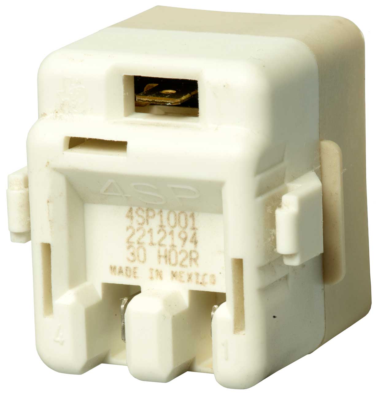
When received the radio was DOA. After removing and
reinstalling all the modules in their sockets a few times each the
radio worked.
The problem was oxidation between the module pins and the sockets.
This antenna was installed quickly to do some tests on PRC-68 Family Radios. When
taking it down it was almost impossible to separate the mast
sections. The copper had oxidized inside the screw thread
joint and much heat and force was needed to get them apart.
After polishing the male and female copper threads Radio Shack
Lube Gel 64-2326
US
5037566 - Lubricating composition and method for making
same. "...provides high corrosion resistance due to the absence of
dissolved air and moisture.."] was applied to the joint before
mating the antenna sections and Coax-Seal (Radio Shack: 278-1645)
was used to seal the open part of the joint.
Lube Gel was also applied inside all outdoor RF coax
connections to keep water out of the joints and prevent
corrosion.
It may be that using Lube Gel in all of the above cases would
prevent a future occurrence of the same problem?
Lube Gel appears to be a modern snake oil that can prevent many
ailments.
After receiving this used but operational radio I cleaned it up
using Windex, a toothbrush and a Rag-in-a-box both outside and
inside.
As part of this process I found a number of screws that were
either very loose or about to fall out.
The lesson is to give a close visual examination and that can best
be done by cleaning.
The front panel had been bashed in. This broke a plastic
part that holds the radio buttons used to select frequency.
After removing and disassembling the front panel the plastic part
could be removed and epoxied back together using J B Weld.
The neon power indicator was held on with one of those flat metal
spring with teeth. The plastic part of the indicator was
broken by whatever hit the panel so the only thing to do was break
the plastic behind the panel. Hot melt glue attached the
front of the plastic to the panel and holds the neon tube where it
was. From the front it looks original. All of the
button caps were removed and cleaned. They had what may have
been tobacco smoke obscuring the numbers.
When received the phone did not work. Opened up the case and
disconnected the internal connector. Visual and olfactory
inspection showed nothing amiss. Reconnected the internal
connector and reassembled. Now phone works. the
connector must have had one or more poor joints. Note this
is a Gold plated connector.
It worked for about a year and it's dead again.
PP-8444A/U
Battery Charger arrived DOA from eBay
Was sold as looking good and "as is" so no complaint. After
some troubleshooting it appears that on both charger boards C5 a
Tantalum cap and U3 an MC34163 Inverting switching regulator have
failed. thus causing a short (<2 Ohms) directly across the 24
VDC input to the charger board. A shorted Tantalum cap was
the problem with the SG-1144 Signal Generator.
The power supply had a number of shorted Tantalum caps.
SB-22 Switchboard
Before cleaning the resistance on one of side of the "D" battery
holder was about 27 Ohms, way too high to pass the current needed
for the talk battery or the buzzer. After cleaning it was below
0.01 Ohms.
After sitting in storage for years with the batteries removed the
battery holder threads developed oxide. When fresh "D" cells
were installed the switchboard would not work. The fix was
to througherly clean both the male and the female threads of the
battery holder and then apply Contax
Oxide
Inhibiting Compound (contains castor oil and
carbon black)to all the threaded battery holder joints. I
got this bottle at the OSH store in Sunnyvale, CA.
There was a time where the U.S. National Electrical Code allowed
Aluminum wire in residences instead of Copper wire. When
joining Al and Cu wires a poor joint might result depending on how
the joint was made. To help solve this problem you can apply
Contax. So you'll find it in the electrical supplies section
of a good hardware store.
This unit arrived DOA. At the time I thought that it
was shipping damage (and that is probably the case) since the
other two boxed units that came on the same pallet worked fine but
this one out of the box was dead. Since it was no more than
parts, I took every module and board that could be removed out and
figured out all the connector and PCB pin outs. In order to
sell it as a parts unit it was reassembled and just for fun
powered up.
It now locked and started working. So cycling the
connections may have brought it back to life.
Hard Drive Failure
For awhile I was using removable hard drive "drawers" as part of a
back up plan. The idea was that you could clone the C: drive
onto another hard drive. Shut down the computer and move the
cloned drive to the C: slot and retire the old C: drive as the
backup. Then power up the computer and run on the new
backup. The beauty of this approach is that you know
immediately if the back up is good. The other hard drive
backup methods have a fatal flaw in that you only find out of the
backup is good after your main drive fails and then it's too late.
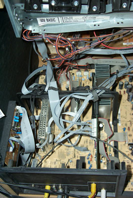
The problem is that the drawer caddy adds another electrical two
connections. The original cable from the mother board now
connects to the back of the cabinet that holds the drawer. and
there's a plug and socket the allows the drawer to mate with the
cabinet. Then there's a short cable inside the drawer
between it's plug and the hard drive.
A parallel ATA cable (IDE cable) has 40 (or in some cases 80)
separate electrical connections the number of connections goes
from 40 to 120. If any of these has a problem the data on
the disk can become bad.
So there's a huge reliability advantage to the new Serial ATA
(SATA) interface because it greatly reduced the number of
electrical connections.
A few months ago my 500GB IDE drive was nearly full so I replaced
it with a 1 TB SATA drive. Now I'm no longer using the hard
drive drawers. In the future I'll be going with only SATA
drives.
This is an in and out of circuit transistor tester. Although
the DC battery check works, the beta test appears dead. It
uses a 1 kHz signal to measure beta. The 1 kHz signal is
coupled in many places by electrolytic caps. There are 5
caps that are all 25 uF @ 10 Volts. The AC impedance at 1
kHz would be about 6 Ohms, but the ESR meter is showing as high as
46 Ohms, almost an 800% error! All the electrolytics in this
meter need to be replaced. After replacing the high
resistance caps it still does not work.
By starting with the schematic diagram and erasing all the switch
contacts and are not being used and then anything in series with
them the resulting schematic has missing connections. Very
strange. Although it may be that lines were erased that
should not have been, repeated audits have not found them.
If you have one of these that's working please let me know.
Dead CRT Computer Monitor
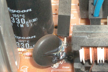
Symptoms: burning electronic part smell. Failure to turn on.
 A
visual inspection found this burned out component. The
schematic symbol under it looks like the letter "Z". It's
located at the AC mains input to the power supply. Right
behind it is a bridge rectifier and a 330 uF cap. The coils
to the right are probably part of the line filter network.
The two blue wires go to the front panel, not sure why since
the front panel (left of photo) On-Off switch has a plastic
connection to the line switch (to the right of photo).
A
visual inspection found this burned out component. The
schematic symbol under it looks like the letter "Z". It's
located at the AC mains input to the power supply. Right
behind it is a bridge rectifier and a 330 uF cap. The coils
to the right are probably part of the line filter network.
The two blue wires go to the front panel, not sure why since
the front panel (left of photo) On-Off switch has a plastic
connection to the line switch (to the right of photo).
What is the dead part?
It might be series connected (inrush current limiting) or shunt
connected (overvoltage protection MOV).
When trying to trace the PCB wiring using the DMM in continuity
mode a chunk of the PCB (around the burned area) fell out.
So I've scrapped this monitor.
I'm thinking it may have been the problem or the cap behind or a
nearby cap may be bad. The ESR checker will be used, but the
first order of business is to find out what this is.
Note the rectangular black plastic part just behind the split
component. The solder connection looks like a donut, i.e.
it's not wetting the lead, a poor quality joint.
Philips 60PP9202 17 Projection TV
Sudden Red Convergence Problem
|
This is the main
board. The large fined heat sink holds the two
convergence STK392-120 ICs. Each of them and three
channels so it takes two for a balanced drive.
There must be a hundred cables that need to be removed to
get that board out of the set.
Beside each board connector there is a reference number
that can be written directly on the ribbon cables, but all
the others will need some kind of label.
|
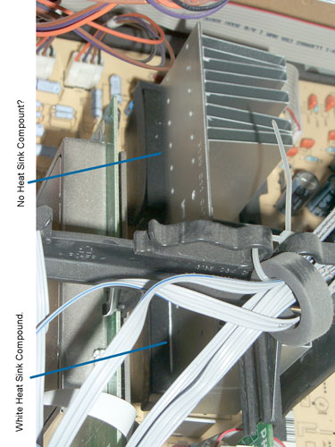 |
In the photo at left it
appears (needs to be confirmed after removing the
STK392-120) that no heat sink compound was used when the
rear chip was installed at the factory. The front
chip clearly shows a bead of white heatsink
compound. There is heat sink compound behind the
rear chip, just not as much.
It would be nice to have detailed instructions for the
replacement of the two convergence driver ICs and the
realignment. If you have it or know where I can get
it please let me know.
|
|
To remove:
I already had the large rear cover and the cover around
the three projection lens assembly removed and the panel
to it's rear, maybe or maybe not required for this.
remove rear connector panel. In addition to the
screws on the outside there are a couple on the inside and
the nut on the "F" connector.
Remove the centeral bridge to get better access for cable
removal.
Remove all the cables (seems like a hundred), labeling
them all so they can be replaced.
Remove (maybe 3 or 4_ screws holding down PCB.
Lift the tabs on the right and slide the PCB out the back.
The spring clips have been removed from the two
STK392-120.
|

|
Using solder wick AND
adding liquid flux the pins were easily desoldered and the
ICs just dropped out.
Breaking the plastic case shows the inside of the
STK392-120. Appears to be all discrete parts, no
ICs. Note the base is the aluminum plate heat sink.
The leads got mangled in the process of removing the
plastic case.
|
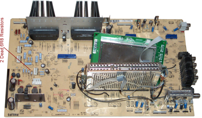
 Note the lower
resistor is marked 6 (the rest has been cooked off) the
others nearby are marked 6R8 or 6.8 Ohms. There are
12 of these always in pairs. The pairs are wired in
parallel and so measure about 3.4 Ohms true or 3.6 on the
DMM because of the test lead resistance. Note the lower
resistor is marked 6 (the rest has been cooked off) the
others nearby are marked 6R8 or 6.8 Ohms. There are
12 of these always in pairs. The pairs are wired in
parallel and so measure about 3.4 Ohms true or 3.6 on the
DMM because of the test lead resistance.
These measure in the Meg Ohms, i.e. totally fried.
Now 27 Jan 2009 to wait for the resistors to be
delivered.
The two fuses tested good.
The resistors are grouped near the three connectors
for RED, BLUE and GREEN, not the STK392.
|
After replacing both
STK392-190 chips the TV was just as bad as before.
It was much faster to pull the main board since all the
cables were labeled.
With no documents it the drill was to check all the
resistors. These were found on the other side of the
board from the STK392 near the connecor marked RED.
|
Installing
the two 6R8 resistors fixed the convergence problem.
But while doing the convergence using the manual procedure
with a grid of 5 x 7 "+" marks and watching some
DVDs a blue halo was noticed surrounding bright
subjects. This is very likley due to contaminated
coolant on the blue CRT.
|

|
It looks like the complete
blue assembly can be removed by removing the 4 screws from
the sheetmetal bracket and disconnecting all the cables
and unplugging the PCB.
All that has been done, except removing the anode HV lead
at the main PCB rather than at the CRT.
How to unplug it?
|
 |
Philips 60PP9202
Blue CRT Assembly
The anode HV wire unplugs from the three way HV splitter
and the yellow ring stays as part of the splitter.
Anyway that's what I hope.
Just above the lens, facing to the right is a cover held
in place by 4 screws. This is the bladder
compartment. At it's center is an inspection hole.
The blus stripe on the connector next to the HV wire was
put on by the factory.
|
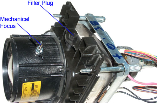
Philips 60PP9202 Blue CRT
Cooling Fluid Filler Plug
The filler plug is opposite to the bladder.
What does "+0.38" Mean?
Let me Know.
The Yellow sticker says:
Delta DigitalTM 260
Covered by U.S. Patents
3M Precision Optics Inc
p/n 313503750721
The fluid is just under the plug so a way to suck it out
would be good to avoid spilling it.
"Projection Tube Coolant" is the title of the eBay item
that's on order.
|
|
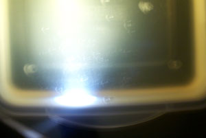
Philips Blue CRT Coolant is
Cloudy
The photo does not show the backscatter as well as you can
see it with you eye. As the Mini Maglight is
focused you can see the bright and dim beams change shape.
The thick fluid also has a yellow tint.
Remove plug, place small finger over hole, ,turn upside
down over tray, remove finger and while tipping slightly
in all directions empty fluid.
|
Denatured
Alcohol is no longer a drug store item. But is
carried by paint stores like Kelly More. It's the
solvent recommended in the factory manual for cleaning the
fluid chamber. Rather than disassemble the chamber
I'm going to rinse it many times using the Denatured
Alcohol. Three times yesterday. Leaving the
plug off so it can evaporate. An ear irrigation
rubber bulb makes a nice tool to put the Alcohol into the
small filler hole.
|
9
Feb 2009 - the bottle arrived and is labeled "Fluid
Coolant" not "Projection Tube Coolant". I
wonder if it's used in some other application?
The ear irrigation rubber bulb is a good tool to put the
fluid into the small hole. If you look into the lens
you can get a very good idea of how much fluid is there
from maybe 10% to 90% of capacity. When the
chamber is almost full you can see the distortion on the
surface as new fluid is added. The plug has a
projection that displaces some fluid when it is installed,
probably as a way to prevent over filling.
It only takes a few minutes to reinstall the CRT assembly
into the set since all that's required is to put in the 4
screws that hold it in place and plug in the cables and
the small PCB.
Now when a DVD starts the blue "DVD" no longer is
surrounded by a blue cloud and at the top of the screen
there are horizontal bands of blue that are visible (which
before was just a blue fuzz ball). The optical and
electrical focus on blue needed tweaking and now the blue
convergence can be done. The only problem left is to
tweak the blue intensity. The picture looks great
and skin tones are great.
10 Feb - A helper can push the navigation ring on the
remote to keep the manual multi point convergence big +
moving (to prevent the timer from turning it off) and
covering one of the two active CRTs then you can adjust
the electrical and mechanical focus on all three
tubes. By watching a good movie the blue intensity
was adjusted then after watching more movie it was
tweaked. Now the image is as good it gets,
much better than prior to the red convergence failure.
Pressing and holding Mute on the remote and pressing any
button on the front of the TV causes it to go into User
Service Mode and no error codes were shown.
|
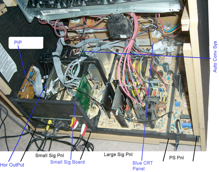
Major
Components
|
After reading
about the failure of the convergence amplifier ICs in projection
TV sets this seems the most likley cause of the sudden red color
failure.
The Philips web page will not sell me a service manual, only
"authorized" dealers can buy it.
Now looking for a source of the STK392-120 chips. I found
two eBay sellers of this chip.
One offers a 2 pack for $12.99 but does NOT mention the brand
name.
The others offer them for $12 to $15 each including USPS mail
delivery, I got a couple of these.
Home Theater Shack -
Link to my post
#222 asking about the Service Manual and where to get the
chips. Post moved to Philips
60PP9202.
The fundamental problem may be the choice of thermal grease.
The early formulations have a thermal resistance vs. time
degradation that the newer types no longer have. For example
Wakefield 126 (accessories.pdf
1.3 MB) Thermal Joint Compound is twice as good as the old 120
compound after 6 onths of cure time. Found this when working
on a 7 Watt LED.
Ohm Meter Readings on the STK392-120
Pin
|
Function
|
7405 rear
|
7404 front
|
1
|
Sub Gnd
|
0
|
0
|
2
|
Gnd
|
0
|
0
|
3
|
Muting
|
1.6M
|
10k
|
4
|
-PreVcc
|
1.4M
|
1.4M
|
5
|
+PreVcc
|
2.6M
|
2.6M
|
6
|
Ch1 +In
|
3.2k
|
3.2k
|
7
|
Ch1 -In
|
3.3k
|
3.3k
|
8
|
-Vcc1
|
1.5M
|
40k
|
9
|
Ch1 Out
|
104
|
104
|
10
|
+123Vcc
|
0.5
|
0.5
|
11
|
Ch2 Out
|
104
|
104
|
12
|
-Vcc2
|
380k
|
1.4M
|
13
|
Ch2 -In
|
3.3k
|
3.3k
|
14
|
Ch2 +In
|
3.3k
|
3.3k
|
15
|
Ch3 +In
|
3.3k |
3.3k |
16
|
Ch3 -In
|
3.3M
|
3.3k |
17
|
-Vcc3
|
2.4M
|
2.7M
|
18
|
Ch3 Out
|
3.2M
|
104
|
All the outputs are 104 Ohms except for 7405 (rear IC that had
minimal heat sink compound) which is 3.2 M Ohm. It's blown
open and Ch3 is probably Red. Note that pin 18 is close to
the center of the heat sink and so will have some heat from the
front chip. If heat is the problem then you would expect
Channel 3 of the rear chip and/or Channel 1 of the front
chip to go since they will be the hottest ones.
The other values are marked red because they are different for the
front and rear ICs.
Dec 2009 - When upgrading my Home
Theater and watching YouTube the blue was way off
convergence and the red was a little off. It turns out that
the new A/V receiver was feeding the projection set 1080i video
and when the repair was made the alignment was not done for that
resolution. While feeding the set with a YouTube video the
multipoint red and blue alignments were done requiring a number of
iterations. After watching a few YouTube videos another
alignment was done.
When a Blu-ray disk is played and the output fed to the A/V
receiver using component video the projection monitor is fed 1080i
video. The image is FANTASTIC!
Service Manual
Available as .pdf from Manual
Zone - Has Parts lists for 82 model numbers but there may be
many duplicates. 1,848 pages.
Patents relating to Rear Projection TV
by 3M Innovative Properties Co (seem to be about the screen
not the optics)
6163402 Rear projection screen, 3M Innovative Properties Co, Dec
19, 2000, 359/443 ; 353/74; 359/454; 359/460 - made for HD
TV
6204971 Glass microspheres for use in films and projection screen
displays and methods
6317263 Projection screen using dispersing lens array for
asymmetric viewing angle, 3M Innovative Properties Co, Nov 13,
2001, 359/443; 359/460 -
6417966 Rear projection screen using internal reflection, 3M
Innovative Properties Co, Jul 9, 2002, 359/453; 359/460 -
6449089 Rear projection screen with enhanced contrast, 3M
Innovative Properties Co, Sep 10, 2002, 359/454; 359/460 -
6515798 Rear projection screen, 3M Innovative Properties Co, Feb
4, 2003, 359/443; 359/449 -
Capacitor Failure
The idea with a capacitor is to have
capactive reactance that's low compared to the rest of the
circuit. The equivalent series resistance (ESR) of the
capacitor should be considerable lower than it's capactive
reactance.
Xc = 1/ (2 * PI * F * C). Values shown in table below are at
60 Hz.
Capacitors - new web
page

EVB
ESR Only Tester

I have made some modifications on the stock tester so that it can
be used to measure the ESR of batteries.
(1) The two large protection diodes need to be removed from the
PCB. They are located near where the banana jacks are wired.
(2) A SPST normally open push button switch is added near the tip
of one of the test leads and in series with the lead. Across
the switch place a 470 ohm resistor. When the probes are
first connected to a live battery the 470 Ohm series resistor pre
charges the internal non polarized blocking caps without hitting
them with a really fast rise time pulse, thus tending to protect
the internal circuitry.
On the face of the meter is a table showing normal ESR values for
capacitors as a function of capactance and voltage rating.
|
10 V
|
16 V
|
25 V
|
35 V
|
63 V
|
160 V
|
250 V
|
1 uF
|
x
|
x
|
5
|
4
|
6
|
10
|
20
|
2.2
|
x
|
x
|
2.5
|
3
|
4
|
9
|
14
|
4.7
|
x
|
x
|
6
|
3
|
2
|
6
|
5
|
10
|
x
|
1.6
|
1.5
|
1.7
|
2
|
3
|
6
|
22
|
3
|
8
|
2
|
1
|
0.8
|
1.6
|
3
|
47
|
1
|
2
|
1
|
1
|
0.6
|
1
|
2
|
100
|
0.6
|
0.9
|
0.5
|
0.5
|
0.3
|
0.5
|
1
|
220
|
0.3
|
0.4
|
0.4
|
0.2
|
0.15
|
0.25
|
0.5
|
470
|
0.15
|
0.2
|
0.25
|
0.1
|
0.1
|
0.2
|
0.3
|
1000
|
0.1
|
0.1
|
0.1
|
0.04
|
0.04
|
.15
|
x
|
4700
|
0.06
|
0.05
|
0.05
|
0.05
|
0.05
|
x
|
x
|
10000
|
0.04
|
0.03
|
0.03
|
0.03
|
x
|
x
|
x
|
Note that the
Impedance of all capacitors
is a function of frequency. As the frequency goes up the
capacitance will decrease because of the inductance of the leads
and maybe the capacitor itself. Typically the smaller the
value of capacitance the higher in frequency it's still a
capacitor. So it's common to see a number of capacitors in
parallel.
Electrolytic
It's the nature of electrolytic
caps to have the electrolyte evaporate. How fast that
happens depends on how well it was sealed. Another problem
showed up around 2002 when a defective electrolyte was used in a
very large number of caps resulting in failures after 250 or
more hours of actual operation.
Low-ESR
Aluminum Electrolytic Failures Linked to Taiwanese Raw
Material Problems. The failure mode is to blow the
vent cap and spew electrolyte. The electrolyte will damage
printed circuit boards beyond repair and that can lead to smoke
and or fires. Electrically the cap looks like an open and
in some cases the guts are blown out of the can and it's
literally empty.
#
|
Cap uF
|
WVDC
|
Xc60
|
ESR
|
ESR/Xc %
|
0.5*C*V*V
|
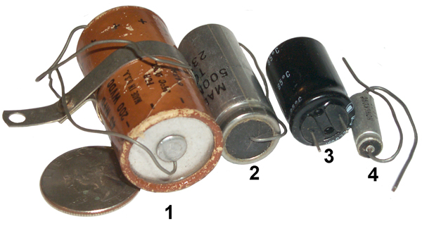
The
formula columns are an attempt to come up with a way to
predict the ESR for a given chemistry cap. Not
working yet.
|
1
|
40 |
200 |
66
|
0.64 |
1
|
0.8
|
2
|
500 |
50 |
5
|
0.19
|
4
|
0.625
|
3
|
2200 |
6.3 |
1.2
|
0.23
|
19
|
0.04
|
4
|
39 |
16 |
68
|
0.30
|
0.4
|
0.004
|
Tantalum
Tantalum capacitors offer a higher
C * V product than electrolytic capacitors in the same
volume, or more commonly in a smaller size package. When
introduced they were adopted by the military and commercial
electronics industries. But if improperly installed
(polarity reversed) they behave more like firecrackers and
immediately explode. Also if subjected to spikes of
voltage or current they will be degraded or fail. The
failure mode is to short out. This causes some up stream
component(s) to fail by burning up possibly starting a fire or
destroying a printed circuit board.
 |
These are tear drop or
dipped Tantalum caps and are the type I've seen most as
dead shorts.
#
|
Cap uF
|
WVDC
|
Xc60
|
ESR
|
ESR/Xc %
|
5
|
10
|
35
|
265
|
1.2
|
0.5
|
6
|
10
|
25
|
265
|
0.35
|
0.1
|
|

|
Trimble 16768-80 SLGR GPS
Receiver Power Supply
#
|
Type
|
uF
|
WVDC
|
ESR
|
C5
|
Tan
|
10
|
35
|
0.42
|
C1
|
Al El |
220 |
63 |
0.39
|
C4
|
Tan |
220
|
10
|
0.05
|
C3
|
Tan
|
?
|
?
|
0.17
|
C4 Hermetically Sealed Axial Tantalum
marking:
M39003
09-0221J
+220uF
10% 10 V
31433
9101AM K
|
PRC-104A Panel Short
|
|
 |
PRC-104A (RT-1209A)
Front Panel Shorted Cap(s)
Marking on the rear cap is:
CX06M685M
8848VME
Dipped Radial Tantalum Capacitors 35volts 6.8uF 20%
Capacitor, tantalum,
6.8 uF, 20% Tol,
-55/+125C, 35V@85C, 23V@125C,
E,
Micro-Miniature: Size E, (E x 3.3" x 7.87"
LxTxH),
Pitch is 0.2", W=0.228", T=0.126", H=0.30"
Bulk, Bag (180 pcs),
6% DF, 2.5 Ohm ESR, 3 uA Leakage
There are two of these caps connected in parallel and
they are across the main DC power supply.
Another PRC-104A panel had this exact failure.
A voltage rating of 35 VDC maybe is too close to the
input voltage range of 9 to 32 VDC?
A 50 VDC 6.8 cap is available T491D685M050AT
that might fit the space.
|
After
replacing the two caps the blown fuse problem has gone
away.
Pressing the LIGHT button turns on the back light.
But the LCD is blank and the handset does not have white
noise.
Bent Connector
|
 |
Visual inspection shows
that he AUDIO connector has been bent or hit causing it
to sit at an angle and it's support PCB has broken
solder joints on the ground pins. |
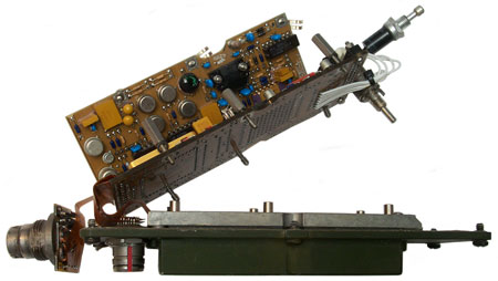 The audio
connector has been separated for inspection. The
two new Tantalum capacitors are the round yellow ones. The audio
connector has been separated for inspection. The
two new Tantalum capacitors are the round yellow ones.
|
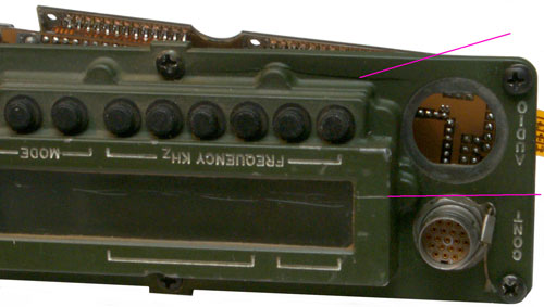
PRC-104A Cracked Front Panel (2 places)
|
Weather
When anything is outside the elements (heat, cold, sun, rain
&Etc.)can cause failures.
Harbor Freight 93068
March 2016 - The outdoor unit stopped working after a lot of
rain.
This is a battery powered outdoor PIR sensor with an indoor
audible alarm. To open it up remove the top center screw
then the battery cover and underneath remove 2 screws.
The problem seems to be that there's rust on the surface of the
PIR sensor. Using a Q-tip and tap water I cleaned the
sensor and it now seems to be working.
Before reassembling I coated the rubber O-ring that is supposed
to seal the two parts of the housing with Silicon grease.
Fig 1

|
|
This may be the A-6F
Classic.
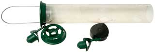
Fig 1
|
This bird feeder is probably 30 years old
and been outside in Northern California all that time.
I think what did it in was the sunflower seeds got wet and
then froze. The expansion broke the tube at the
bottom.
A replacement tube is on order.
The seed
tray at the bottom was an option. It catches
some of the seeds that the birds would otherwise knock to
the ground.
An excellent value considering how long it lasted and that
it can still be repaired.
|
|
Fig 2 This Droll Yankees bird feeder was in
the garage all dirty. After taking it apart and
cleaning, it's now back in service.
The green parts are metal. Only the tube and black
bottom cap are plastic. Not all parts shown.
 |
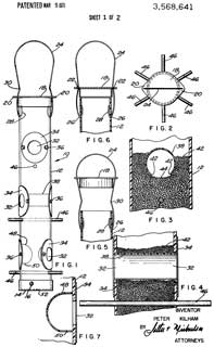
|
3568641
Bird feeder, Peter Kilham,
(before Droll Yankees), App: 1969-03-03, 119/57.8; D30/127 -
The design is over 50 years old.
|
Static & Electrocution
Electrocution
Often static electricity is blamed for what I call
electrocution. For example, I was asked to investigate why
the yield was very poor on an expensive polar discriminator
assembly that used four back diode detectors on each housing.
Static discharge was the assumed cause of the problem, but
the real problem was a soldering iron that had about 15 VAC on
the tip. Back diodes can be blown with only a few volts.
The work bench had maybe a half dozen soldering irons (all
expensive anti static grounded tip type) and only when the
defective iron was used would the diodes be blown.
Static
Some definitions
Antistatic: Preventing or
inhibiting the buildup of static electricity.
Since static electricity is
generated by moving electrons from one insulating material
to another the current involved is very small so a high
value resistor between the two objects can easily equalize
the voltages and prevent buildup. A pure plastic bag
that can generate static electricity can be treated in a
number of ways so that it has a high resistance and then
will not generate static. This is an anti static bag.
Electrostatic Discharge (
Wiki
Talk): The sudden and momentary electric current that
results when an excess of electric charge, either stored on an
electrically insulated object or on an isolated conductive
object, finds a path to an object at a different electrical
potential (such as ground).
Getting shocked in a warm room
in the winter time when touching a metal object is because
of ESD.
Lightening is an example of ESD.
It's very important to see the
distinction between these two ideas.
I sit on a chair with plastic wheels in a room with wall to wall
carpet. I used to use a "chair mat" to get a hard surface
so the chair wheels would roll, but plastic wheels on plastic is
a static generator and often I would get a static shock.
Using antistatic spray would help but was not a cure.
Placing a sheet of plywood over the mat (could have
removed the mat) solved the problem.
When working on a PC I leave the power cord plugged into the
wall. This has a danger factor in that the power switch
has hot line voltage and maybe some spots on the power supply
are line hot. But it also connects the chassis to line
ground so that if you touch the chassis before you touch any
static sensitive device the static will be grounded.
Wrist straps are not good grounds, but rather have a 1 to 10 Meg
Ohm resistor in series between the human and ground. This
way you are not grounding someone and making a human
electrocution possible. If you want to make your own
ground strap by using a piece of copper wire and a ground lead,
be sure to insert a 1 MegOhm resistor in series.
Many companies that work with static sensitive components, like
microwave parts or disk drives, have special flooring that is
conductive and the workers wear shoes that are conductive or use
heel straps that make a high resistance path from the floor to
the ankle. This way a person walking does not build up a
charge. Also the chairs and stools have grounding chains
always in contact with the floor so a moving chair does not
generate a charge.
When packaging a static sensitive component many people make the
mistake of thinking that using an "antistatic" bag will protect
the component. THIS IS NOT THE CASE. An "antistatic"
bag will not generate static but does not protect from
static.
It
is easy to destroy the component while it is in a sealed
"antistatic" bag. Just walk across a carpet on a dry
day and touch the top of the bag while it is sitting on a
metal work bench.
The proper way to protect the static sensitive component
is to wrap it in Aluminum foil or use one of the conducting
Faraday cage type bags.
PS
Magazine 2004 Issue 623
page 42 has published this information about what
antistatic means. (PS I'm in Ukiah, CA, not San Diego)
EEVblog
#3 – Anti Static Myths Busted -
Office chairs that have plastic wheels rolling on carpet
protectors make excellent static generators. They are a
real problem around computers. It's better to get a sheet
of 3/4" plywood for the chair to roll on.
This
$0.70 Component SAVES your Circuit?! EB#59, 12:16 - TVS
Diode (Wiki,
P6KE15A),
MOV (Wiki: Varistor),
GDT (Wiki: Gas Discharge Tube,
Telephone Protector)
Printed Circuit Boards
A way to get a double sided board with vias is to use Express PCB. They
have a prototype service that will supply 3 boards that are 3.8 x
2.5 inches and have tin-lead reflow but have neither Silk
screening, solder masks, routing nor multi-layers. There are
a limited number of drill and pad sizes. You can put a
number of smaller boards on one and separate them yourself using a
Tungsten carbide tipped scriber (General Tools
Model 88CM, Catalog No. GEN-31116 ). A straight edge is
needed for the first pass but all the succeeding passes are in the
groove.
In the 1960s we used shoe eyelet's to connect the top and
bottom PCB traces in double sided boards. They were
installed and formed using a motor powered machine then hand
soldered. This was a military approved way of PCB
construction and much easier than soldering a wire and cutting
off both ends.
2002 - update on cutting printed circuit boards. I got a
single speed skill saw at Wal-Mart, chosen for it's low price
and that fact that it had a couple of nuts as part of the flat
surface. By drilling a hole through the 1" thick workbench
top and making a short slot for the blade, then mounting the saw
underneath the workbench using a couple of flat head screws,
with only the blade sticking up through the slot I now have a
reciprocating table saw. By using a fine tooth metal
cutting blade you can separate 25 to 100 PCBs. This bench
mounted $10 saw turns out to be quite handy. The screws
that pinch the blade turn out to be an M4 thread and have been
replaced. It takes a lot of finger strength to cut small
boards since you need to hold them down very firmly or they will
jump up and down with the blade. It makes a lot of dust
that you should not breathe. It takes a little more than
50 mils for the saw kerf.
2006 Update - A small 8 inch Mini Shear
Break designed for working sheet metal does a nice job of
cutting 1/16 inch PCBs. Although I think I know why the
first one is not broken waiting for parts to arrive from China,
I've received an email from another user that said his would not
cut boards out of the box.
Replacing soldered in ICs
After having identified a bad IC
that's soldered into a PCB I used the following procedure.
Cut all the IC leads using diagonal cutters. It took a
couple of passes to get them all cut on one side of the
IC. Then bend the IC up and unsolder and pull each lead
one at a time. Then press the IC down and cut and desolder
each of the pins on the other side. This destroys an IC
that was bad already but greatly reduces the chances of damaging
the PCB.
3 May 2006 - Next using a solder sucker clean out all the
holes. Install the new IC and solder in place. This
may not be so easy. Sometimes neither solder wick nor
solder sucker will get the solder out of the hole. If a
piece of wire that's the right size for the hole is chucked into
a Dremel tool then cut off so that only a board thickness plus a
little is above the chuck face. It can be used as a drill
bit on the highest speed. Another option that has also
worked for me is to use a sewing needle held in a pin vise to
push a hole into the solder, sort of swaging.
Using Solder Wick
6 May 2006 - If just prior to using the solder wick you wet
about 1/4" with RMA flux it will work much better. This
may be for two reasons. First the liquid conducts the heat
better than air and second, the flux cleans the solder wick of
oxides allowing the solder to bond easier. This makes the
difference in being able to get solder out of small diameter
holes or not getting it out and needing to drill as above.
Flux
The key property of
solder flux is that it's boiling point is higher
than the melting temperature of the solder.
This makes for excellent heat transfer. The
shape of a soldering iron tip is typically conical
or cylindrical and so touching the iron to a wire or
circuit trace makes for a small contact area and
poor heat transfer.
If a small amount of flux is applied and the iron
located where flux is present then you have much
better heat transfer. If there's a hole with
solder and a component lead you need to fill the
hole with liquid flux to transfer the heat to the
solder. If you just flux the solder wick you
may or may not be able to get the solder out of the
hole.
Flux pens and a handy way of applying liquid flux,
but don't order them on the same order as other
items because it will slow down your whole order
since they are shipped as a hazmat item.
|
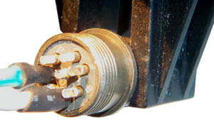
This is the
construction of the A.C. Power cord for the
M455-1 Power Supply. The
connector was second hand, i.e. all the cups were full of
solder. The wick was flat and a little wider than the O.D.
of the pin but using tweezers it could be formed into a shape
that would fit into the solder cup (after using the wick in the
normal way to get down to the solder cup). Then using a
very pointed iron (the one used for
SMT
soldering) and trapping the wick between the iron an the
protruding part of the cup the solder was sucked completly out
of the cup.
Flux & Solder Wick
It's very important to add liquid flux to the solder
wick to transfer the heat. This will make the
difference between no wicking and wicking!!
|
The "A" pin at about 2 o'clock is the one that's been cleaned,
no point in doing pins that aren't going to be used.
The black jaws are on a Panavise Jr.
Also when using shrink tubing in very tight quarters like this
don't use a size that's a tight fit because when the wire
insulation distorts you will not be able to pull the tubing over
the joint. A pair of tweezers was used as a heat sink to
keep the shrink tube from shrinking. The tweezers were
held closed by a spring like used in the
257477BA Battery Adapter.

Here
the Panavise Jr. is tipped on it's side and the rotation of the
ball clamp has been adjusted so that there's a three point
support (the base, the end of the adjustment arm, the tip
of a jaw) that's stable.
This is a great way to hold connectors while they are being
assembled.
Soldering Surface Mount Devices - seperate web page on
Surface Mount Technology
Soldering Iron Tip Maintenance
When finished using a soldering iron I used to clean the tip and
power down the iron. This results in the tip oxidizing and
getting pitted. Much better to clean the tip and put a big
glob of solder on it just prior to power down. Also the
modern tips come with a silver colored plating, they are not raw
copper and this helps maintain the tip, so these should not be
filed.

Reverse Engineering
Naming
Most of the equipment that I have
reverse engineered made use of printed circuit boards. If
the board has part ID information you can use the same part names,
but if it does not (most of the time) they you need to name each
part as well as have a way to identify each lead. Lead
identification for ICs is easy since they have standardized pin
numbering, diodes have an anode and cathode, but resistors and
other parts don't have lead specific markings and so you need to
keep track of which end goes where. This can be done by
using a flat bed scanner to make color images of each side of the
board and then adding part names, like shown in manuals.
Conformal Coating
Often it's necessary to use a
continuity checker (beep Ohms mode on a DMM) to find out what's
connected to what. This is especially true for multi layer
boards. When working with military boards you will find that
they often have conformal coating that is thin and
transparent. So when you place a probe tip on top of what
appears to be nice shinny solder you will NOT make electrical
contact. A quick check is to put both probes on the same
pad, yet not touching each other. If there's no continuity
then you know you're working on a coated PCB. One way around
this is to push and/or rotate the probe to punch through the
coating and into the solder, but the same pad may need to be
probed many times and this really chews up the pad. A better
way is to use a large sewing needle held in a machinist's pin
vise. The meter probe can be put into the hollow metal
handle or connected with a clip lead.
BEEP Mode of DMM
The DMM may BEEP when the connection
is not really a metalic path but instead is a low resistance
path. So it's better to not use the beep function and
instead look at the Ohms reading.
Caution
When reverse engineering some thought
needs to be given to possible DC shorts. When working on the
FS5000 Spy
Radio I smoked a PCB trace that was on one of the interior
layers. This could have been avoided by fusing my test
fixture DC power leads (both the hot and ground).
Cable Testing
When reverse engineering a cable be
sure to look for jumpers that connect multiple pins on the same
end of the cable. These will show up if you test all
possible combinations of pins at both ends of the cable.
Loctite
Loctite is great for keeping screws from coming loose,
BUT should not be used near plastic parts. For the very
first production lot of my 2577BA
Battery Adapter I used Loctite 222 on a 6-32 screw that went into
an Aluminum spacer. BUT the 1/8" thick plastic sheet between
the two showed severe cracking when the Loctite set up and the
whole batch had to be scrapped. I think what happened was
some Loctite got into the space between the screw and the plastic
and when it set up it expanded and destroyed the plastic.
Needless to say I don't use Loctite in this application.
Rubber Parts
Rubber (and synthetic equivalents) biodegrade. Air
and/or water will cause them to disintegrate. Insulation
will turn to dust and hoses, gaskets, O-rings, etc. will
fail. In older automotive applications this is the most
common failure mode I have seen.
The O-rings in the U-229 connector get hard and/or
develop cracks when they age. This makes it difficult to
install/remove them.
A similar thing happens to the O-ring that seals the battery
magazine to the DAGR GPS receiver.
My 1929 Rolls Royce and the 1934
Rolls Royce used steel tubing between the vehicle frame
and the engine where today a rubber hose is used. They did
this by forming 3 or 4 turns about 3 " in diameter so that the
tubing would never be stressed past it's elastic limit as the
engine rocked back and forth. Of course the engine did
this only on acceleration or engine braking, when idling you can
balance a Nickel on top of the radiator.
The O-rings between the steel cylinder sleeves and the aluminum
block of the all the RR cars with a V-8 engine is a real
disaster. It's a certainly that one of the huge number of
rubber hoses carrying water or the rubber seal in the water pump
that also has to act as torque stop, will fail while you are
under way resulting in the engine block over heating.
Overheating those cylinder seal O-rings results in failure to
seal the water or oil. If it's the upper O-ring that
failed you will get water coming out of the weep holes in the
block since there are two O-rings at the bottom, the lower
O-ring seals out crancase oil, so if oil is coming out the weep
hole it means the bottom O-ring has failed. Needless to
say replacing the O-rings requires major engine
work. If the aluminum block that's about 1/8" thick
between cylinders cracks then it can NOT be welded since the
aluminum is plastic impregnated. But you might be able to
use an epoxy, didn't try that.
Bonding
Loctite
404 super glue can be used to join rubber parts. See:
YouTube: AVE: Make
any size O-ring, 2:13 - use Acetone to clean first.
Plastic Parts
If you search this page (CTRL<F>plastic) you will get a
lot of hits. While plastic is much lower in cost than
metal it does not last. Maybe there's a failure mode
that's similar to how rubber parts biodegrade.
Modern cars use a lot of plastic parts. The 1975 Volvo
has a plastic radiator but it's much more fragile than a metal
radiator. A similar thing happened with the Mercedes C230
plastic water manifold.
One of my pet peeves is not knowing how a manufacturer is
trading off reliability
and cost. That's to say some products are designed
with a Mean Time Between Failures of say one year while a
similar product my have a MTBF of five years. I'd
like to know the MTBF for high value products I buy so I could
decide which one I'd like.
Another factor is the ability to repair the product.
There are tow aspects to this. One is getting access to
the information needed to make a repair. This is being
fought in the courts see for example Apple and John Deere
tractors. The other aspect is some high end products, like
large flat screen TV sets where the ICs are custom made for a
particular model and there are no replacement ICs. If one
burns out then you need to throw away that product. See: Throw away
products.
Car Radio Knob Broken
There are small knobs that can be
popped out and then pulled out to set balance, bass and treble
settings. The plastic knobs seem to fall apart.
Repaired using J-B Weld epoxy being careful to keep it out of the
central hole. You can see some gray epoxy in the after
photo.
Cleaning
In order to make images of equipment I use a digital
camera or color flat bed scanner.
Both of these methods show up every spec of dust so cleaning is
needed to get good images.
Dirt
Dirt is the most common thing that needs to be removed
so the first cleaning step us to use water to wet the
dirt, a tooth brush, tooth pick, small brush, pipe cleaner to
scrub a little and a clean dry paper towel or tissue to wipe dry
and clean. Often knobs need to be removed to clean under
them. Engraved labels often have dirt covering the white
paint and need extra scrubbing.
Very Old Masking Tape
DE-Solv-It , Contractors' solvent available at K-Mart
- removed tape from a BC-611 radio
that nothing else could touch.
Tape adhesive
This
web page has a number of methods to remove tape adhesive as
well as other stuff.
Goo
Gone™ (Magic
American Corp.- Cleveland OH) has received a number of
recommendations on the Tek list server also works for decomposed
foam.
Rust
Oxygen, moisture and about
anything can combine to make corrosion. There are many
commercial rust remover products on the market. Many use
phosphoric acid. (Wiki:
Rust,
Rust
Remover). Renaissance Metal De-Corroder says it's made
of : Amine comples of hydro-oxycarboxilic acid. But the only
references to the key indegrient are ads or references to this
product. It has the look and feel of phosphoric acid.
Available from the Gemmary.
If paint primer is applied to bare metal it affords NO protection
from rusting. Primer is by design a porous coating so the
the paint overcoat will bond well. Leaving a car outdoors
with just primer is a great way to rust it (ask how I know
this). The second time I used a special paint made for ships
called
Corroless.
I picked this brand after reading the paint shoot out test results
in Skinned Knuckles magazine since it got the highest
ratings. Rustolum and POR15 were not as good.
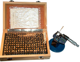
I've
recently been doing things that involve metal working and a number
of times I've come across vapor phase rust prevention (aka:
Volatile Corrosion Inhibitors or Vapor Phase Inhibitors)
papers. There's a brown sheet of paper behind the plastic
laminated cal certificate in the box lid of the
pin gauges. That's the
special paper. My local machine shop ships metal parts to me
with some of the paper in the packaging. It has some shelf
life so is not a permanent solution, but one worth knowing about.
4604227
Vapor phase and surface contact rust preventive composition,
Stauffer Chemical Co, Aug 5, 1986, 252/389.2 ; 252/389.61;
252/392; 508/399
Protective Packaging
carries
moisture
barrier bags and
Vapor
Corrosion Inhibitors paper. Their web pages have a lot
of good info.
When rust forms in a
threaded fastener
it becomes very difficult to remove the fastener. Many
people use WD40 but that's the wrong thing. WD stands
for Water Displacement which is what it was made to do. For
getting stuck nuts, bolts or other items loose a penetrating oil
like
Kroil, is what works
best.
For removing rust from metal parts that are not to be painted
consider
Evapo-Rust.
For a user report see
VY2AC on Prince Edward
Island - Ridding Parts of Rust!
Lawn Mower (Scott's Model 22815x7A)
I put this article just below Rust
because that's one of the problems the lawnmower had after sitting
outside for a number of years.
This is a self-powered walk behind lawnmower with a vertical shaft
engine and single cutting bar. 6.0 HP B&S 4-cycle
engine.
There were a number of problems:
1) When the starting cord was pulled it failed to retract.
It turns out nothing was broken it was just a lot of friction
stopping it from retracting. The fix was to squirt some
Kroil penetrating oil into the joint between the rotating part and
the fixed part (a circle about 5" in diameter). This
probably could be done without any diss-assembly.
2) The drive belt had many cracks and broken parts and was very
stiff and needed to be replaced.
37x105, John Deere p/n: M77167
3) The drive axle was frozen (would not turn, would no come out to
allow Removing and Replacing the drive belt). It was
necessary to remove wheel support plates to free the axle.
4) the bolts holding the wheel support plates were frozen (rusted)
together and Kroil did not help so when torque was applied one
bolt snapped, so 4 replacement bolts and nuts were purchased along
with the new drive belt. Loctite 222 was used when
installing the new nuts and bolts rather than using lock washers.
5) the teeth on the inside of one of the drive wheels have been
almost all chewed off. I've ordered a couple of new wheels
from eBay using the B&S p/n 672441.
Storage
When in storage anything is subject
to oxidation, humidity and temperature cycling. Military
packaging typically involves sealing the product in an air tight
waterproof bag. This limits the oxygen available to what was
there when the bag was sealed, once that's used up there will be
no further oxidation. Also the humidity is constant inside
the bag.
You can get these same benefits simply by sealing things into Zip
Lock plastic bags. It helps if you zip up all but the last
1/4" then compress the bag to get out as much air as possible then
zip up the last bit. This also minimizes the space that the
bag occupies.
Try to place items in storage where temperature cycling is
minimized, but this is not always an option.
Design Defects
In some cases it is sold as a "Feature".
In some cases it kills the product or manufacturer. Long ago
HP came out with a doppler radar module. The idea was to
hook up an antenna, supply DC power and get the audio doppler
signal out. It involved a lot of specialized construction
and tooling. But there was a design defect that greatly
degraded the signal to noise ratio compared to a different
topology. The product disappeared from the market.
LCD Backlight in PRC-126
In other cases is just fixed. The first PRC-126 radios added a back light
to the LCD display and it also was supposed to be night vision
goggle compliant. The designer placed a very dark green
filter above the LCD and this worked great for night vision goggle
use and I'm sure that's where all the effort was focused since
this was a new high tech area, BUT you could not read the LCD in
daylight.
Later radios fixed this by placing the dark green filter between
the back light and the LCD.
The Rolls Royce cars with V-8 engines use an aluminum block and
steel cylinder liners. The aluminum thickness between
cylinders is maybe 1/8" or less. When (not if) the rubber
O-rings sealing the steel liners to the block fail (see Rubber Parts above) the engine overheats causing
irreparable cracks in the thin block wall. The last I heard
Rolls was going to buy engines from BMW. It's too bad that
the company has been going down hill ever since Mr. Royce
died. The cars he designed were built to be reliable.
RR won many races, not by being fast, but by
finishing. That's why Lawrence of Arabia used the PII
chassis as the bases for armored cars. The PII was also
featured in one of the Indiana Jones movies.
Fluke Test Leads
The new style test leads that come with the Fluke model 87 DMM and are made by
Fluke have failed three times. The failure mode is that ALL
the strands of wire fracture in the same plane about 1/8" past the
strain relief behind the shrouded banana plugs at the probe
end. This is not a stress type fracture where you can see
deformation of the metal, but rather as if the wire had been cut
in a shear. This has happened to me with 3 different sets of
test leads. Each time Fluke was notified not only that there
was a failure, but that it was most likely a design or
manufacturing defect that caused it.
One of the symptoms of the failure is that the meter reads zero
volts when in fact there is voltage in the circuit. This is
a safety issue if the meter is being used to determine if a
circuit is hot prior to working on it.
My guess is that there is some type of work hardening stress
(thermal or mechanical) applied to the strands in the
manufacturing process and a small amount of flexing of the wire
causes a fracture.
30 Nov 2006 - It turns out that the test leads were NOT intended
for DMM use. I have purchased DMM test leads and they do
have strain relief on both ends, unlike the above test leads that
did not have strain relief on the probe end. And that's
where they failed.
May 2015 - This time it was Greenlee UL Listed 67KM test leads
that failed. I thought my Fluke 87V DMM was reading very low
on DC current, but it turned out to be bad test leads AGAIN!
Test Leads causing low DC current readings

|
It's not clear why the black banana plug
showed erratic
Ohms readings? It's not severed like the prior lead
failures, but there might be some broken strands.
It's hard to be sure because I cut some strands
when removing the molded part and the insulation.

|
Lap Top Li-Ion Battery
My Sony Vaio PDGA-BPZ52 Lap Top Li-Ion battery has failed.
It's rated at 14.8 volts 4.2 AH. When connected to the lap top
the battery window shows it's model and serial number and says it's
been discharged 31 times and has zero charge and that it's being
charged. But after hours no charge accumulates in the battery.
Inside there are 12 cells each rated at 3.7 volts, so 4 cells in
series would make the 14.8 volts. There seems to be 3 plastic
cell holders each with 4 cells. The cells are all
interconnected with welded tabs. Only 5 tabs are connected to
the PCB so there's no way that each individual cell is being
monitored. The cells are connected in groups of 3 in parallel.
So the left tab is ground, the next tab to the right is 3.7 V (3
cells in parallel), the next tab to the right is 7.4 v (3 parallel +
3 parallel), next tab is 11.1 V and the right hand tab is 14.4 V.
Along the narrow side there's a PCB with over a dozen ICs.

The plastic case can be preyed open without breaking it. Next
step is to unsolder the 5 battery connections from the PCB and check
the cells. When 5.25 volts is applied across any of the groups
of 3 parallel cells no current is drawn. The Li-Ion charging
instructions say not to try and charge under these conditions, so it
looks like the cells are really dead. Now to see if
replacement cells are available.
Precision Time & Frequency
GPS 1 PPS Stability
The GPS system provides the most
precise timing signal for the amateur. A GPS receiver, like
the now obsolete Motorola M12+T (soon to be replaced see the
Synergy web site) will provide a 1 PPS output with jitter under 10
ns and this can be reduced either in hardware or software by
applying the sawtooth correction to each pulse.
But the jitter can be increased by a couple of orders of magnitude
if there is multipath. In my case living in a canyon with
100+ foot trees surrounding the house I have severe
multipath. The fix was to set the GPS receiver elevation
mask to 60 degrees (it was set to maybe 10 or 15 degrees).
This solved that problem.
Installing Coax Connectors
When installing crimp type coax
connectors there are
documents
that tell you how much outer jacket to cut off, how much shield
to cut off and how much insulation to strip off. But
somehow now matter how hard you try the numbers don't seem
to match your connector. But after you have soldered the
center pin in place and you find that you need more or less
distance between the pin and the cable shield it can be changed
by sliding your hand along the cable while holding it firmly,
toward the connector reduces the distance and away from the
connector increases the distance.
Also at the start of the assembly process when the furl is put
on the cable before beginning, also slip a few inches of shrink
tubing that will go over the furl. At the very end of the
assembly push the shrink tube up behind the connector and shrink
it. This provides some strain relief.
Counter Trigger Settings
For about a year (after the above
problem was fixed) my data on Cesium standards showed a change in
frequency, which should not happen with a Cesium standard, but
does happen with crystal and Rubidium standards. This
probably was caused by improper setting of the Time Interval
counter triggering. The correct trigger settings for both 1
PPS inputs and for frequency inputs (1 Mhz, 10 Mhz, etc.) are:
- Trigger level at 1/2 of the voltage swing (need to confirm
using BNC-T and scope) in my case it turned out to the
1.25 volts. For example if the SynPacIII with M12+T is
putting out a TTL (5 volt) pulse and the source and load are
50 Ohms then the pulse height is divided by 2. Setting
the trigger level to 2.4 volts (the normal TTL trigger level)
will be very wrong.
Kitchen Compactor Jam
 |
To reduce the volume of recycle items, Al
cans since it's hot now (July 2009) I started to use the
kitchen compactor for the first time in many many
years. It worked a couple of cycles then jammed with
the plunger down. Removing the four screws attaching
it to the counter allowed pulling it out. Then
removing the four top screws gave access to the drive belt,
see photo.
Once jammed there was no response when working the
switch. A probable cause is that the can got pushed to
one side tripping the container safety switch. To
restore operation the belt was worked off the large gear
wheel and while pulling on both sides of the belt the wheel
was turned clockwise (from top see photo) thus manually
raising the plunger. Note the threaded rod was well
down at the jammed position and comes up as the plunger is
raised. If you're not paying attention you'll
get grease on you hand.
It's now working fine. |
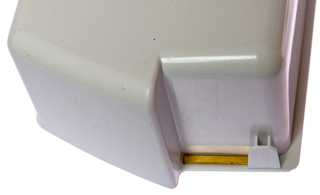
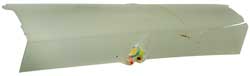
Refrigerator Door Shelf Failure
Some time ago there were two
failures of the door shelf where is just fell dumping it's
contents. The problem is very thin plastic where the load is
concentrated.

|
|
|
Brass shim was on good side
of the shelf.
|
This
means that when the refrigerator was cleaned a couple of
weeks ago the brass shim fell out and was replaced on the
wrong side and the shelf was installed in a precarious
way. A slight nudge, like I did yesterday caused the
shelf to fall. This time I've taped the brass shim
so it will not fall out (it was trapped before but no
longer).
|
Refrigerator Light Lens Failure
This is for the Whirpool (Kirkland/Costco) SS25AFXQ00. Parts
drawing No. 34.
WP2254920 Whirlpool Light Lens OEM WP2254920
After two of the four tabs were broken, the plastic was pressed
against the light bulb causing packages on the other side of the
plastic to get transferred onto the plastic.
Need to replace filament bulb with LED bulb that runs much cooler.
GE Electric Wall Oven Cold (GE JKP14WOP1WG)
When I was baking bread (
Recipes: 5 Minute Bread) the
oven was a little cold, but recently a pie came out with the
bottom dough raw, not cooked at all.
The temperature sensor was replaced during the bread making
attempt to get it working, but had no effect. Gambling on
replacing the controller board does not make sense.
I pulled the oven to measure for a new one to replace the GE model
J KP14W0P1WG that was installed when the house was built in the
late 1990s.
Once out and on the kitchen floor the element resistances could be
easily measured and they both looked OK. The controller
assembly was considered for replacement during the bread baking
investigation but there's a no return policy since it needs to be
special ordered and it was hundreds of dollars.
Looking further I could see electrolytic caps on the oven
controller and so thought there's a good change that's the problem
and at that point changed from working on a replacement to seeing
if the old controller could be repaired. The key to the
repair would be using the
ESR-Cap meter
since there's no schematic or repair documentation for the
controler. Just test all the electrolytic caps and see if
any are bad. Two were.

|
Hole for New Oven
There are dual 15 Amp breakers (240 VAC) now in place for
the old oven.
The new oven requires a dual 20 Amp breaker setup (240
VAC).
Need to find out what size the wires are and if their
ampacity is good for 20 Amps.
If not then repairing the old oven makes more sense.
If the wires are too small to carry the current for the
new oven then there's going to be a real problem.
|
|
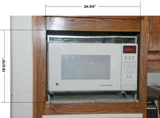
Hole for Microwave Oven
There is 3" of space above the top of the cutout until you
get to the bottom of the cabinet.
There is an additional 1" on the left and 1-1/2" on the
right if a bigger hole is needed.
|
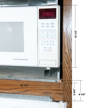
|
Separation between Microwave and traditional wall oven.
See photo above, there's a few inches of height from the
top of the microwave opening and the bottom of the
cabinet.
The microwave height of 12-1/2" does not include the feet,
with the feet it's more like 13-1/2".
|

|
Wiring for New Oven
There is an outside breaker panel that holds the electric
meter and there is this indoor breaker panel.
The upper left two breakers (50 Amp 240 VAC) are for the
air conditioner.
The next two below the AC breakers are for the oven.
The breakers are only 15 AMP (probably from the oven
spec),
but the wire size is the same as for the 50 Amp AC wiring,
so no problem to change to 20 Amp breakers for the new
oven.
|

|
Beakers for New Oven
The old 15 AMP breakers are marked:
Challenger
Type C215
120/240 V AC
Cu/Al
HACR Type (UL)
Listed Cir Bkr
2 Pole LNJ-554
E7819-S-91 09 04
(SA) LR48907
|

|
Can Oven Controller be Repaired by replacing
Electrolytic Cap?
The Back element has a resistance of 29.3 Ohms (1965 Watts
@ 240 VAC) and the Broil element measures 17.5 Ohms (3291
Watts @ 240 VAC) so they look OK. Leaving the
control board as the most likely problem.
In this photo the release bar has been pulled out, then
the flex circuit connecting to the buttons on the front of
the oven has been pulled out a little then lifted over the
stop pins and is free of the controller.
|
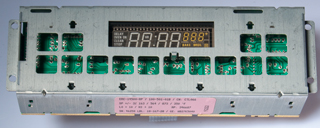
|
The label reads:
ER-14500-RP / 100-501-01B / CN: CTL066
SP +/- 3% 163 / 564 / 873 / 350 'F
LO + 10 / HI +
10
RP: 346687
SN: 46258 LBL: 18-167-28 / GE: WB27K5040
|
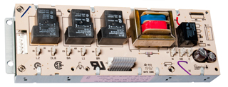
|
Back side of controller
marked: Robertshaw
The slow degradation suggests that the problem is not with
the relays, but rather the electrolytic capacitors.
Bending up the tabs holding the relay board and opening
the hinge to free the flex cable allows board seperation.
|

|
Two Bad Caps
The two boards seperated.
The electrolytic caps upper left to lower right:
ID
|
V |
Clbl
|
Cmeas
|
ESR
|
C10
|
35
|
470
|
370
|
0.46
|
C8
|
35
|
1000
|
828
|
0.36
|
C7
|
25
|
47
|
49.6
|
4.7
|
C17
|
35
|
4.7
|
000
|
---
|
C1
|
35
|
4.7
|
000
|
---
|
It looks like C1 and C17 are bad.
Aluminum Organic Polymer caps are not available in this
value so ordered (2 Dec 2011) some low loss electrolytic
caps
Mouser p/n: 647-UKL1E4R7KDDANA 100 for $16.50 +
shipping.
|

|
Bad caps in Analog Temperature Sensing Circuitry
The connector has two white wires and they are from the
oven temperature sensor. The big IC is a LM324N
Operational Amplifier. This end of the circuit board
is where the analog DC temperature signal is processed and
so is sensitive to leaky or open caps like C1 &
C17. There
are also a number of yellow Tantalum caps that need to
be checked. On closer inspection (stronger
glasses) the small yellow caps are not Tantalum, i.e. they
are not polarized and are just low value ceramic caps so
unlikely bad.
The location of the bad caps is consistant with a gradudal
degradation in the temperature control.
|

|
Bad Caps are way too Small
It turns out that the new caps (4.7 uF 25 V are larger
than the factory caps which were rated 4.7 uF 35
volts. The higher factory voltage rating means that
they are way undersized for the combination of capacitance
and voltage and so may have been made using the fake
electrolyte Wiki: Capacitor
plague).
I installed them folded over in case the extra height
might cause a clearance problem with the relay board just
above this one.
|
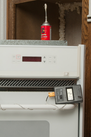
|
WORKING!
The ESR-Cap meter identified
C1 & C17 as defective and they were.
I noticed that the thermocouple was reading very high so I
stopped the oven and reset the calibration from +35 to
+5. If the thermocouple can "see" the heatintg
element then it reads much higher because of radient
heating. Best to have the pizza stone or something
in the oven to block radient heating the TC.
The foam is part of the mouse proofing. I've used a
flat blade screwdriver to force steel wool into the cracks
and then used the foam to hold it into place. You
don't need the foam if you can jam the steel wool tight,
but that didn't work here.
Note when the oven is at temperature the outside is cold
to the touch. (tested on floor prior to reinstalling.
The thermocouple is showing 210 C (410 F) a little hotter
than the 400 F set point.
The oven now gets to operating temperature in a few
minutes, not the half hour it used to take to get close.
|
GE Electric Wall Oven Error --F1--
(JKP14WOP1WG)
20 Dec 2013 - Oven beeps and displays --F1--
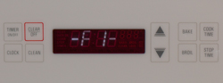
That translates to something wrong with the front key-panel.
I'm hoping that it just need to have it's ribbon cable reseated a
number of times. That did not fix it.
But . . . pressing timer causes the beeping to stop for a few
minutes and then allows using the other buttons to operate the
oven. So it may be that just disconnecting the piezo beeper
and then pressing timer then whatever oven settings are desired
would be a workaround?
Jan 2015: someone strong here to help pull oven and sit it on
floor. Disconnected only a couple of things and pulled the
circuit board. Rather than pull the complete metal box, I
just bent the tabs and after disconnecting a few cables removed
the bottom PCB leaving the top board wired to the oven. This
took only a few minutes.

Checking the big electrolytic caps with ESR
meter shows
C8 marked: 1000 uF 35V tests as 922 uF. & 00 Ohms.
(the 00 Ohms looks suspicious, but may be OK)
C10 marked 470 uF 35V tests 431 uF 0.04 Ohms (less than 20% low
capacitance so may be OK)
C7 marked 47 uF 25 V tests 90.8 uF and 41 Ohms (way too high on
ESR and strange capacitance reading)
I have all of the above on order, should ship today and be here in
a day or two. Note C7 is close to the display and is most
likely the problem. But since I've got it opened up will
also replace C8 and C10.
ID
|
test
after removing
|
New
cap before installing
|
|
uF
|
Ohm
|
uF
|
Ohm
|
C7
|
90.8
|
41
|
173
|
0.85
|
C8
|
922
|
0.00
|
1030
|
0.01
|
C10
|
431
|
0.04
|
490
|
0.03
|
The caps were not the problem.
30 Jan 2015 - Working. The problem was related to the flat
metal contacts that go from the display, around the edge of the
printed circuit board and are soldered to the board and/or
contamination on the trace side of the board. The metal
straps were each positioned so as to maximize the space between
each one and none touching and the board was washed with alcohol
and an Exacto knife used to remove some solder flux left there by
the factory.
GE Dual Wave III Microwave Oven JE1468K
The microwave is mounted in the wall just above the electric
oven (see above).
The control panel locks up (26 Nov 2014). This has
happened a couple of times before and the fix was to turn off
the breaker, wait an hour, then power up the oven.
The display would sometimes show "RESET" and pushing any button
had no response, but then after leaving it alone it would start
working. Today I opened it up to see if it was another bad
capacitor, and sure enough of the 4 electrolytic on the control
board C14 tested as: 7.2 Ohms and no capacitance with constant
beeping. On remeasuring it read 7.2 Ohms and 1.9 uF.
This is consistent with the idea of healing.
I replaced C14 and the oven is now working, but I'm not sure
C14 was the problem. It may have been poor connections
that were fixed when the cables were unplugged and plugged back
in.
Cap
|
Marked
|
ESR
|
Cap
|
C1
|
470uF
25V
|
0.13
|
473
|
C2
|
470uF
25V |
0.15
|
447
|
C4
|
1000uF
25V
|
0.05 |
1001 |
C14
|
1uF
50V
|
6.8
|
1.9
|
Left Inside
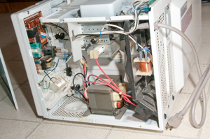
|
Close Up of PCB & Wiring
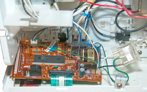
|
Back of PCB with C14 marked

|
Front of PCB

|
Air Conditioning Compressor
The AC died during the heat wave of 2023 July 20.
The technician asked me to set the thermostat so that the AC
would come on. The fan at the top of the compressor
assembly was not turning, so he gave it a push and it started
spinning and at the same time the compressor started
working. A neat diagnostic trick! The fix was to
replace the 35uF+5uF 440V 60Hz AC start capacitor.
|
Note Electrical disconnect removed
and on top of breaker box.
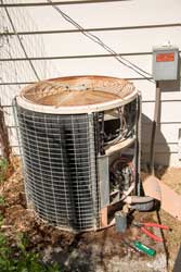
|
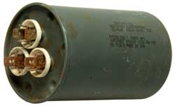 |
Not sure if bad cap or poor electrical
connection (the connectors are badly corroded)?
A new cap is working.
|
HERM
R
|
HERM
C
|
FAN
R
|
FAN
C
|
Fluke 87V
|
--
|
34.2 uF
|
--
|
4.97 uF
|
ESR-micro v4.0s
|
0.26
|
41.2
|
1.33
|
5.59
|
Numbers look like good cap, so probably corroded
connection.
|
Air Conditioning Fan
2024 July heat wave - I tried turning fan but no luck, did not
start.
2024 July 11 - turning fan in wrong direction: it resists
movement, turning in correct direction: starts and system is
working. This would be explained by poor
electrical connections to start capacitor. Both the
fan and compressor turned off, so its looking like this 32 year
old system needs a new outdoor unit.
, 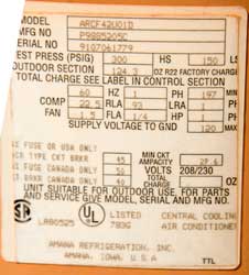
|
Model: ARCF42U01D - I
think the 42 means 42,000 BTU or dividing by 12000 BTU per
ton = 3.5 Tons.
|
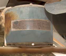 |
Grainger
- Item
- 617K24
- Mfr.
Model
- 1860PEP
|
Laptop Headset Connectors go Bad
The problem is walking away
while wearing the headset.
That puls the cord at right angles to the plug centerline
breaking the wires.
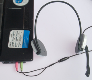
|
The fix it to:
1) replace the 3.5mm stereo Mike Plug.
2) add a short extension cord to the Mike and Earphones.
That way if you walk away the headset will unplug from the
extension cord.
|
|
|
Comfort Zone Stand Up Portable Room
Heater Squeals and Stops
The first time it was used
since last winter this Comfort Zone stand up heater squeals
like a banshie with a warble and then the fan stops.
Removing the 6 self -tapping screws requires a Philips (+)
blade screwdriver and a nut driver type will not work
becuase the screws are located inside holes that are too
small in diameter to pass the nut driver.
Once opened up a drop from a Radio Shack pocket oiler was
applied to both the top and bottom shafts leaving the motor
and the fan spun by hand and this was repeated a few times
intil the fan spins easily. Power on and it's running
fine.
|

|
Battery Replacement
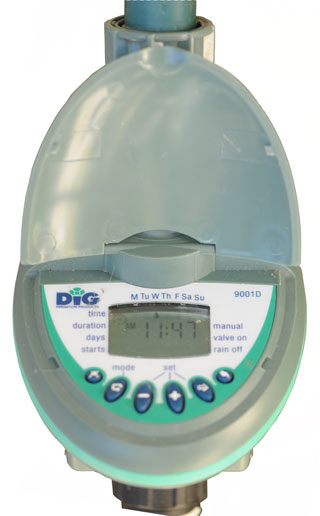 |
Dig 9001D
Hose-bib Irrigation Timer
The hose bib timer that feeds the bird bath and 5 gallon
bucket would not turn on when the manual on/off button was
pushed. The battery icon was showing an almost dead
battery. After opening the battery cover and seeing
that a 9V battery was needed I went back inside and got a
new 9V battery before disconnecting the old weak one rather
than remove the old battery then go get a new one in the
hope that if I minimized the time when no battery was
connected I could avoid reprogramming the timer. After
getting the new battery I oriented it like the connected
battery so it would just be a un-snap and snap
operation. The switch took just a couple of seconds
and the timer came up showing the correct time.
On the bottom row of the LCD, that's blank in the photo at
left, is where the low battery icon appeared.
|
|
|
Orbit
62056 - 1 Dial Hose Faucet Timer with Brass
Swivel

|
This is a much easier to use unit than the
Dig 9001D shown above.
1) the large dial allows selecting the function instead of
using the small buttons and trying to see the icon that
results.
2) the display is much larger and can be easily read without
bending over.
3) it uses 2 each AA batteries, which is more amp hours than
a 9V battery and allows using the Lithium 1.5V AA if it need
to work in freezing temperatures. But for freeze
applications it needs to be wrapped to keep it from
freezing.
If you press manual while in AUTO mode it comes up with 10
minutes to go, but that can be changed using the + or -
buttons.
Patent 7637475
Solenoid, Orbit Irrigation Products, Dec 29, 2009, - uses a
moving permanent magnet latching between two poles so only a
pulse of energy is used to change state.
|
Water Misting
It's July and the outside temperature is in the 100 to 105
degree F range.
By opening the skylight in the upstairs bathroom and a window on
the North side of the house on the ground floor air circulates
keeping the house about 20 degrees cooler than the outside temp.
To get more cooling I've added a Orbit Flex Cobra Mister (Model #
30360
Home Depot SKU #
968869).
just outside the downstairs window, but in about 15 minutes the
garden hose burst.
That was fixed by using a hose repair kit and a Hose thread to
Hose thread pressure regulator (similar to Home Depot: Model # R463CB
Internet # 100210697
Store SKU # 798282) on the hose bib feeding
the mister.
In the evening the inside temp may be higher than the outside
temp, then it's time to shut off the mister and open all the
windows.
Hoover Upright Vacuum
The vacuum was making a lot of noise
and shaking. Removing the belt had no effect, i.e. there was
a problem related to the motor impeller. A chunk broke off
and was still in there being beaten up.
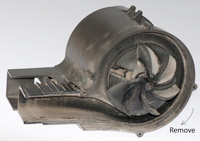 |
Click on photo at left to
see larger version.
Notice there's a chunk missing from the impeller (they
call it a fan). This was caused by one of the screws
that holds a "U" clamp
on the belt side backing out and getting lost. That
allowed the motor assembly to tip and then the impeller
hit the casing, or maybe
it just ate something that was too hard.
To remove the impeller clamp the belt end in a vise (the
shaft is round - no flat) since this is where the belt
rides and turn the fan clockwise, i.e. it's a left handed
thread.
|
While apart other parts were replaced: the lamp, belt, Type-A bag
and a new screw for the "U" clamp. About $18 in parts (Sep
2011).
Door Does Not Latch
Ever since I've been in this house
there are a couple of bathroom doors where the latch does not go
into the strike plate unless you tug on the door. Sighting
when my eye is at the same elevation as the center of the strike
plate shows that the latch tongue is vertically centered on the
hole in the latch plate, so the problem is that the door is not
moving close enough to the jamb. The reason may be that a
painter allowed paint to form a fillet which is acting to make the
jam thicker.
The solution is to scrape out the excess paint (a
Swiss Army Knife worked).
Self Closing Hinge Spring Broken
Hager 426-R Door Closer Body R-7189
The spring snapped. It's been about 21 years. If
used once per day that would be about 21 * 365 = 7,665 door
openings.
5/32" hex key needed when new to set tension.
Aeron Office Chair
I bought this new chair in 2002. It was made by Herman Miller who
manufacture modern furniture including the Eames
Chair. The Eames and Barcelona
chairs are probably two the most famous furniture designs
of all time. In 2013 The hydraulic cylinder at the base
failed and allowed the seat to tip at an angle. It turns
out the Herman Miller has a 12 year warranty on these chairs so
today the repairman from Trope
Group (formerly BB&T) in Santa Rosa stopped by and
installed a new cylinder.
The repair man used his cell phone to take a photo of the left
arm that has some cracks and maybe they will send a replacement
for it.
That's fantastic customer service!
The old cylinder with a central pin on the
base at left.
Sear removed as well as top plastic cover to get access.

|
New style cylinder valve is a lever at top.

|
The cable-clamp tie-wrap at right on back
tension shaft.
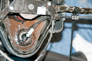
|
Left Arm Cracks

|
|
|
Second Office Chair
Got this one so I could have two office desk spaces. It's a
Staples
Tempurpedic. I didn't know it at the time, but the
wheels were not correct for hardwood floors. It has 5 legs
each with dual plastic wheels. These are not good for
hardwood floors. One of the wheels broke, so I got a
replacement set that have 7/16" dia posts that are 7/8" long to
match the old wheels. While the old dual wheels were 2" dia
and each new single wheel is2.5" diameter, the diameter difference
really does not matter, or may be an improvement as they roll in a
much smoother fashion than the old wheels. If you have an
office chair with hardplastic wheels you might upgrade to these
wheels with rubber tires. eBay heading: "Anyke 2.5" Office
Chair Wheels Swivel Heavy-Duty Casters Replacement Fit for Set".
Fig 1
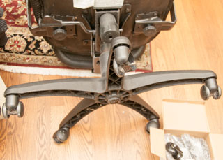
|
Fig 2 The screw driver used as a pry bar
makes it easy
to get the old wheels pulled off.
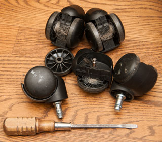 |
Fig 3 2019 July: New wheels have rubber
tire at center so are very smooth.
They also are single wheels unlike the prior dual wheels.
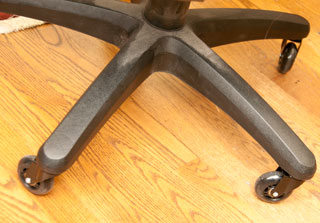 |
Fig 4 Over time the hard plastic has worn
on the floor.
 |
2022 May 1: There are ball bearings showing
up on the floor.
|
|

For some time this unit did not have enough power to spin the
cutting blades. In order to get it to work you could
partially remove the head and if held just right it might work.
The real solution, not in the instructions, is to put a very
small drop of clock oil on the
inside of the head were the blades rub. Now it spins very
fast and does not even slow down while cutting. It may be
that some other oil, like sewing machine oil, might work (but I
doubt WD-40 would work in the long run because it's really not a
lubricant).
Plumbing Stuff
Kohler GP77759
Shower Mixing Valve
In June 2006 I replaced the GP77759
mixing valve because there was a slow leak when the valve was
off. Now, 26 July 2010, the valve will not shut off and the
whole house needs to be turned off. The problem is an O-ring
is jumping out of it's seat and not sealing.
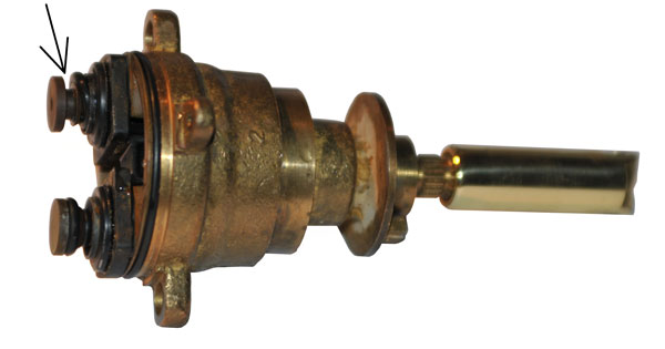
Restoring the O-ring to the proper place does NOT fix the problem,
so I have a second mixing valve on order and will not use the
shower after returning the O-ring to it's proper place. i.e.
if the valve is opened it works, but when you try to turn the
water off it does not shut off and the O-ring moves. I
installed it with some Lube-Gel and will try it just prior to
installing the new valve.
The real problem may be improper installation. The valve
body has threaded connectors for compression fittings, but the
installer just stuck copper pipes into the body and soldered
them. This may be overheated a plastic part?
Rather than ordering just the GP77759 cap (rocket ship) shown in
the photo above, I changed my order to the 76851 Kit that includes
the "rocket ship" and the "binoculars" plus some O-rings to
completly rebuild the valve.
The GP77759 valve arrived (it was supposed to be replaced with the
76851 kit). It's now all plastic, not the brass like the old
one.
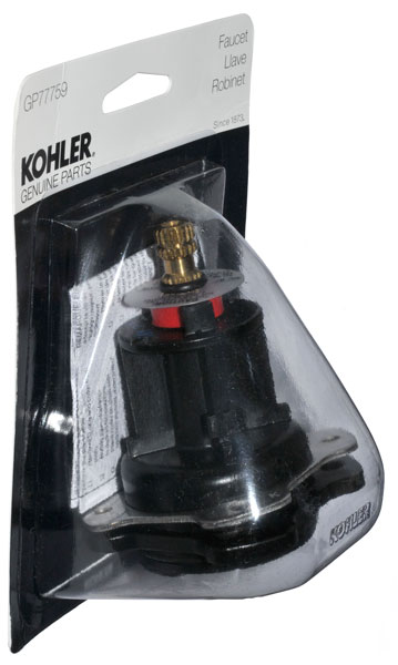 |
|
GP77759 Mixing valve
(Rocket ship)
|
GP500520 Balancing Valve
(binoculars)
|
|

|
The master bath shower stall has two shower heads. The
opposite shower head has a problem that it leaks from the shower
head when the tub is filling. This indicates a bad
mixing/balancing (binocular) valve.
Patents
3724480
Pressure Compensated Mixing Valve, (Kohler),
5445181
Mixing Valve, (Kohler), Aug 29 1995,
137/98 ; 251/85;
251/86
Kohler Sink Valve Backwards
 |
The hot valve (on the left)
is shown as it should appear when off, but is in fact in
the full on position (the shutoff below the sink was
turned off so it would look correct).
The fix is to pull the hot valve and rotate the core 180
degrees.
|
Kohler Shower Temperature Hard To Control
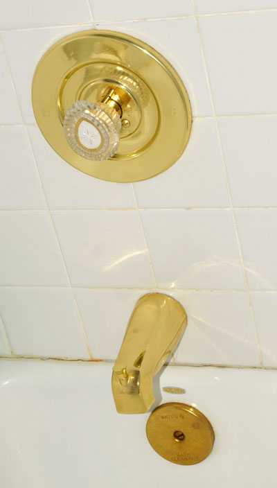 |
It turns out this was easy
to fix.
The problem was a loose screw holding the knob to the
valve.
Using my Swiss
Army Knife I removed the screw cover and tightened
the screw.
|
The seat stopped working. Neither the front or back wands
extend when those washing functions are activated. No
water flows from the retracted wands. There is a trickle
of water from a short tube beside the wands.
Major Parts (shown in wiring diagram Fig 3 below):
Fig 1 Bottom Open View

|
|
Fig 2 Top Open View
 |
|
Fig 3 Wiring diagram
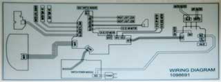 |
|
Fig 4 Option panel side
 |
|
Fig 5 Water, AC input & Control side
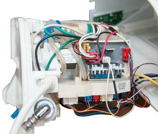 |
|
Leak in Sunpentown SB-2025L Fitting
The washer that came with the
washing toilet seat does not seal the joint between the house
valve and the T fitting.
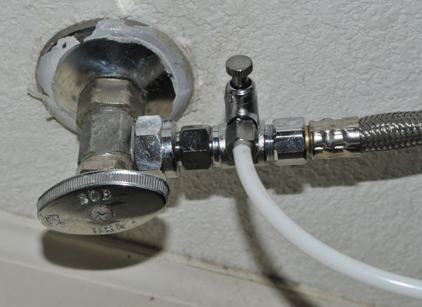
Toilet Tank Crack
Another leak was caused by a hairline crack in the ceramic toilet
tank. Rather than replace the tank (or toilet) which is an
expensive item, I'm trying to use Silicon rubber to patch it from
the inside. You can see the crack on the top edge of the
tank just above the center of the flush handle. Photo taken
after the first coat of Silicon rubber has cured overnight.
A second coat is being applied and again left to dry overnight.
Ended up replacing toilet.
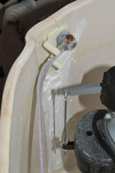
Leaking Flap Valves
It turns out the the tank with the crack also has a leaking flap
(drain) valve. The leak check method that I've heard
involves putting food coloring into the tank and then seeing if it
shows up in the bowl. That method does not work on black
toilets. A simpler method is to just turn of the valve at
the wall and check the next day to see if the water level has gone
down. The closed valve method showed that I've got two
toilets that have leaking flap valves. The first attempt was
to buy a black rubber replacement valve that did not have the
float. It turns out that the open link chain was too short
to reach the handle lever inside the tank. Another
replacement flap came with the float and it's chain was the
correct length.
|
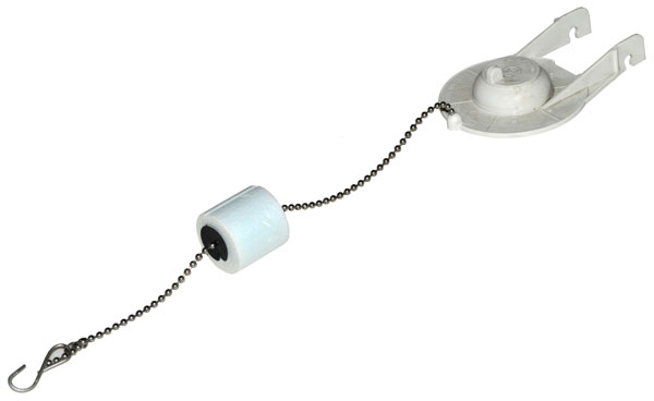
|

The rubber gasket is green and lumpy. The seat has
no gasket and should be smooth, but has green deposits
that need to be removed using a kitchens plastic scrubbing
pad.
|
Bottom of tank showing
bottom of flap valve assembly.

|
Replacing the flap valve
did not fix one of the toilets, so the whole flap valve
assembly needed to be replaced. The gasket that
should seal the assembly to the tank can be seen to be
less than optimal, and probably the source of the leak
between the tank and bowl. Will know in a hour or
so.
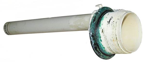
|
Kohler Cimarron Class 5 Toilet does
not "Gulp"
After it was installed the new Kohler Cimarron Class 5 Toilet
started failing to "Gulp", that's to say it did NOT flush
poop. To get it to flush may take many many attempts at
flushing. My plumber said the toilet was working fine and
I needed to get Roto-Rooter to bring out their TV camera.
I asked Kohler about the problem and they said the problem was
with either the trap or vent. Today (28 March 2017)
Roto-Rooter came and I showed the technician the toilet and
after a few minutes he said he knew what the problem was.
Answer: If you have well water (our water comes from a
local water company and they get it from wells) or if you follow
the “If it's brown, flush it
down; if it's yellow, let it mellow" then
there's a problem with calcium build up. This happens in
two places, the small holes that allow flush water to rinse
the sides of the bowl and more important the main flush water
jet that is aimed at the exit opening of the bowl. In my
case this jet was almost totally plugged. The technician
just put his rubber gloved index finger in the hole and easily
cleaned it. Now the toilet gulps like it should.
The Armour/Prine 3/4" wire brush RP77262 works
well to clean the large hole.
Toilet Maintenance: Once a month (maybe once a
quarter) put a cup of CLR into the bowl and a cup in the tank,
per the instructions.

|
7094742
Hard surface cleaning
compositions containing a sultaine and a mixture of
organic acids, Rosemary
A. Gaudreault, Jelmar,
Llc, Aug 22, 2006
7368417
Hard surface cleaning
compositions comprising a lauryl hydroxysultaine, Rosemary
A. Gaudreault, Jelmar,
Llc, May 6, 2008
8569220
Hard surface cleaning
composition, Rosemary
A. Gaudreault, Jelmar,
Llc, Oct 29, 2013
9228159
Hard surface cleaning composition, Rosemary
A. Gaudreault, Jelmar,
Llc, Jan 5, 2016 |
Unrelated to the toilet problem.
There is also an enzyme that helps keep the septic tank
working. One brand is "Earth Enzymes".
Roebic "Main Line Cleaner K-97" is used to help keep the drain
pipe clear of sewage solids and to make the pipe more
slippery, reducing the problem causes by low flush toilets not
being able to get the solids moved into the septic tank or
city drain.
Cleaning Bowl Holes
Called Kohler and sent photos of the inside of
tank so they would know model numbers, but never heard
back. Asked about the size of the main hole, did not
hear back.
So have purchased a couple of wire brushes
(1/2" and 3/4") to see if they fit.

|
Armour Line 1/2" RP77261
Armour Line 3/4" RP77262
|
Flap Valves now obsolete
April 2015
The conventional toilet in the master bedroom did not always fully
flush. If you held the handle down for a minute or two there
was a fifty fifty chance it would work.
The plumber installed a new Kohler Cimarron Class 5 low-flush
toilet (
Wiki)
that uses the "AquaPiston" canister flush valve . What a
huge improvement in flushing and 1.26 gpf efficiency. Note
this is not a pressurized tank type but just an improvement in the
flush valve.
8806669 Toilet flush valve with reducing
cross section valve
seat, Kohler, Aug 19, 2014
PS the Flushmate IV toilet uses a pressure tank that gets it's
pressure from the house water pressure, but these have had some
explosion problems.
It's not clear which would use less water over a year, this Kohler
Cimarron or a dual flush toilet (
Wiki).
The reviews of the Kohler Cimarron say it is not prone to "skid
marks" like some other low-flush and dual flush units.
Outside Irrigation valves
These have failed 3 times in 12
years. They fail leaking when there is no power to turn
them on. In two cases the leak was to the outside of the
valve and the water showed up in the valve box. These are
what would be called slow leaks. In the other cast the
valve failed as an open even though no power was applied and the
water came out the normal irrigation locations. This is
what would be called a fast leak (especially when there was a
break in the 1/2" tubing).

|
Back Irrigation box
valves
Position No. 1 was not used. There have been two
leaks, one through a valve and one to the outside of a
valve.
|
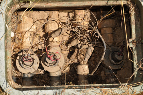
|
Side Irrigation box
valves
Valve No. 3 failed and was removed and the supply line
capped.
|
The
best solution will be to remove the box and all the
valves along with the manifold and replace the complete
manifold assembly with one using a better brand of
valve.
|
Hydro Swirl 96K6 Pump
A decade or so ago the pump died and I replaced it.
In the past week (July 2012) there have been some flakes of
rubber in the tub and on two occasions the pump has stopped
and would not start again. But did start later, like
there was a thermal switch shutdown. My guess is that a
seal is going bad adding load and overheating the pump.
If I can get a new pump in time then I'll look into replacing
the bad seal and keep this pump as a backup for when the new
one has a problem.
PS there are two windows with a great view of the
forest. It's common to see squirrels, birds, stars, the
moon or planets. VERY relaxing.
The Genini Plus II pump used in the Hydro Swirl is probably
also used in a number of water pumping applications like
outdoor hot tubs, spas, Jacuzzi type bathtub, etc. It's
much more economical to replace the pump impeller and seals
than replace the complete motor-pump-air switch assembly.
PS Do NOT use a pumice stone and then run the pump. The
abrasive particles will eat up the seals.
Hydro swirl 96K6 Jacuzzi Bath
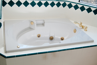
The toilet room is just to the left of this photo and
there's a trap door that provides access to the pump.
|
Jacuzzi Bath Pump
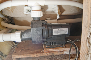
Looking into the trap door at the pump.
Label on top:
ITT Industries
spec: 0034F00C
model: NR2A-C
3/4 HP, 120 V, 8.5 Amp
|
Label:
Model: 426009
Number: 52707
Date of Manf: 8/23/91
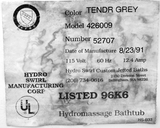
|
Pump Rebuild Kit
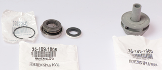
Impeller for Gemini 4647100 Pump (on right) ITT 4647100
35-109-1300
Pump Seal Kit Genini Plus II:
ITT 6000600
ITT 6001531
ITT 6001601
(O-ring: O-028B70)
|
Pump after cleaning

|
At the center of the motor end there's a
hole
over the end of the motor shaft to give access to the
screwdriver
slot needed to hold the shaft while unscrewing the
impeller.
After removing the pump nose, as shown in the photo
at the left, a flat blade (-) screwdriver can be used to
keep
the motor shaft from turning as the impeller is
unscrewed
like a light bulb.
|
Pump with impeller removed & motor
seal installed.
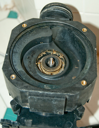
|
I pulled on the motor seal but it
separated leaving the
metal cup part on the motor and the spring and seal
came off. So I used pliers on the nose of the
metal cap
to pull it out along with the O-ring.
|
Stack showing the relative positions of
the impeller, impeller seal,
motor seal and O-ring.

|
Now the pump will
run for a full 30 minutes (maximum timer setting)
without problems and it seems to be running faster.
|
Refrigerator Water Filter: PUR
4396508 Whirlpool
Before changing the filter it took 21 seconds to fill a
measuring cup with 2 cups of water.
After the new filter was installed it took 17 seconds.
Looks like it's carbon only.
SB-2025 Magic Clean Washing Toilet
Seat Mother Board
For the past few times the maids have cleaned the GFI that
protects the downstairs bathroom has tripped. I think this is
related to the failure of the mother board in the SB-2025
washing toilet seat. After their last visit resetting
the GFI did not restore power (all the LEDs were off) to the
seat.
Replacing the mother board fixed the problem.
To remove:
* unplug electrical cord
* press button at back and slide seat off mounting plate
* remove seat and set on floor near by
*remove 2 + screws at back
*remove 1 + screw under control are
* press in the latches (see Fig 3 below) to ease out the
bottom plate
* Note: there is a white connector that has not cable attached
* remove 15 cables from the mother board (note they are color
and size coded)
* remove 4 + screws and remove old mother board.
** reverse the above steps
Fig 1 the new mother board
K3-N V2.1
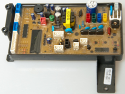
|
Fig 2 SB-2025
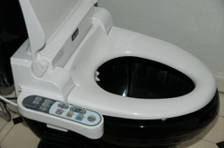
|
Fig 3 Inside the SB-2025 (latches along
front edge)

|
Fig 4 the old mother board K3 V1.6
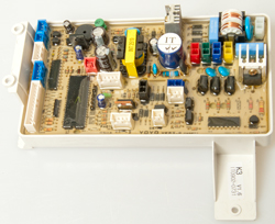
|
In Ground Swimming Pool Skimmer
Float Valve Assembly
The skimmer has two pipes in the bottom, the one closest to the
pool comes from the bottom drain, the one away from the pool goes
to the main pump inlet.
This float valve assembly sits above the open ends of those two
pipes. When the water level is above the skimmer weir the
float, trapped inside the valve assembly, is in the up position
and lets the skimmer water get sucked into the main pump.
The float will no longer float when the pool water is low.
The bottom of the float is flat and seats on an O-ring blocking
the skimmer from the main pump inlet thus preventing air getting
into the pump line.
Under normal conditions the float is always under water and
that water is at or very near the surface of the pool where the
water temperature has the most variation. This temperature
cycling of the float will cause it to fill with water if there's
the slightest pin hole or crack.
It turns out that the new Penair float assemblies received in
the first and second quarters of 2015 have been defective.
The problem is that the float, that's made up of a top and
bottom have just been snapped together without being
glued. But the top and bottom half of the cage assembly
that trap the float have been glued. So the factory has
the glue but for some reason has stopped applying the glue to
the float seam where it's most needed.
To confirm that the float seam is not glued it's possible to
put a fingernail in the seam and with a slight rotary motion
cause the seam to open.
If the float valve assembly is removed most if not all of the
water that the main pump moves will come from the skimmer.
If the pool water level gets too low the pump will suck air, a
bad thing for the pump.
If you don't have a float valve assembly it might be possible
to use a 4" or 6" PVC cap with the open end down to cause the
pump to suck only from the main drain. This defeats the
skimmer but would allow the system to work. I haven't
tested that idea so use at your own risk.
4 July 2015 - The new float valve Pentair 506160 Skimmer Float
Valve Assembly that was installed a month ago has become water
logged because they did not glue the seam of the float.
If you know of a replacement not made by Pentair Let Me Know the make and model.
Propane Tank Leak
Could smell propane when outside near tank. Leak on the
input fitting of the pressure regulator. Leak between two
red parts.
 |
This is a 200 gallon capacity tank.
I know of another same size tank were it leaked through
the tank metal.
Is propane corrosive to the tank metal? let me know.
|
Propane Tank Empty
Moved to Smart Meters\Propane.
Forced Air Furnace & Air Conditioner
Feb 2016 - The house was cold because the propane tank was
empty (it's been cold for here i.e. in the 30s at night).
But after the tank was filled the furnace did not start.
In the past the problem has been a burned out ignitor, but
that's not the problem since when powered up the ignitor lights
up and the controller cycles through 3 attempts then stops and
the red light blinks.
See Furnace Controller under
Electrical.
Icicles in Freezer
2020 Feb 11 - This is a side-by-side refrigerator freezer (Wiki)
that has a cold water and crushed/cube ice dispenser in the
freezer door.
Water that was supposed to go into the ice maker was running
into the freezer making a mess by freezing things into a solid
block. I think the cause was overloading the freezer thus
blocking the circulation ports to the refrigerator.
2020 Feb 26 - The replacement ice maker is working. I'm
still not sure of the root cause of the icicles in the
freezer. For sure it was caused by the water feed to the
ice maker running more than it should. But why did that
happen? Overloading the freezer and refrigerator, or
something to do with the ice maker. I think the later
because the ice maker failed some tests (see Fig 2).
WARNING - The heater element
appears to be on all the time and on two occasions I've burned a
finger! It's a good idea to turn off the breaker for the
refrigerator-freezer and let it sit for a few minutes before
working on the ice maker.
Fig 1
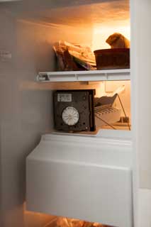 |
Whrilpool
SS25AFXL side-by-side -
eBay replacement unit:
Refrigerator Icemaker Ice Maker for Whirlpool
Kenmore Kitchenaid 2198597
less than $50 including shipping.
Troubleshooting with AC on:
L & N: 120 VAC (AC power good)
H & T: 120 VAC with ice in tray (bad thermostat)
L & M: 120 VAC bail up or down. (but wheel no
turning)?
|
Fig 2
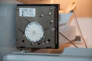
|
Terminals (white letters at
left):
N: AC line Neutral
M: Motor
H: Heater
T: Thermostat
L: AC Line
V: water Valve
|
The cover has been pulled off exposing the
timing wheel.
When Terminals T & H are shorted (paper clip with
insulating tape) for a few seconds then clip removed the
Timer Wheel will make a full turn. (Wednesday but not
Thursday)
After reducing the amount of stuff in the freezer and
refrigerator and triggering a Timer Wheel turn, I'm going
to wait till tomorrow to see what's happening.
Shorting V (Valve) and L (Line) should turn on water. (It
still does.)
|
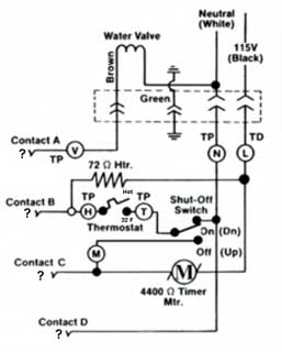
Circled letters are electrical test points, see above
photo.
The function of the A,B,C,D connector at the left is
unknown. Let me know.
Maybe goes to the in door water & ice dispenser and/or
ice feeder motor?
|
At the top is a 4 terminal
connector with:
Water valve (V), Ground, Neutral AC Line (N), Hot AC Line
(L)
Meter
Test
Points
|
Power
OFF
Ohms
|
Power
On
ACV
|
L &
N
|
|
120
|
L &
H
|
72
|
|
L &
M
|
4k4
|
|
N &
V
|
150 to 350
|
|
T &
H (32 F)
|
short
|
|
T &
F (water)
|
open
|
|
Power On using insulated jumper:
T & H (simulate thermostat closing w/bail down): timer
turns |
|
Fig 3 Bottom Left view of replacement unit,
but it's got 2 broken plastic parts.
The output tray is detached and the front cove is split at
a corner.
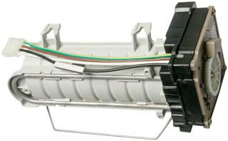 |
You can see the "U" shaped heater element
and
the cable that connects to the freezer.
Cable has thermal switch to detect heater runaway.
|
|
Fig 4 The bottom screw bracket and its
mounting screw did come with the
new unit. Note notch at rear of water catch cup
needs to be knocked out of
new unit.
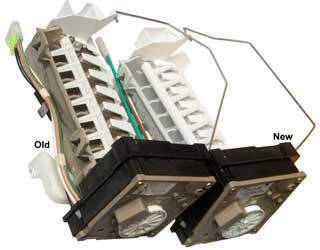 |
|
|
Fig 5 The bail on the new ice maker (right)
was in the wrong location.
See the old unit at left for correct location of bail.
The new ice maker has a ramp for the cubes, the old one
has a cliff.
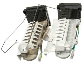
|
|
|
Fig 6 Freezer after old unit and ice tray
removed.
The two top 1/4" hex screws need not be removed just
backed off a couple of turns.
The bottom 1/4" hex screw does need to be removed.
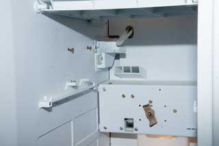 |
Shorting T (thermostat) and H (line high)
for a few seconds
starts the timer wheel turning and at the end of that
cycle
runs the correct amount of water into the ice tray.
Did this to get the cycle started.
There have been a number of dumps of ice, so it's working.
The water supply tube (with the top cut out to prevent a
freeze plug forming) can be seen. This is the source
of the water that made the icicles.
The propeller.metal bar at the back is to turn the helix
that pushes the ice cubes out the door or drives the ice
crusher.
|
|
Fig 7 Front clockwork removed

|
The two silver color pins at the bottom are
the heater contacts.
Both of them look clean and the associated fingers on the
front
Clock panel look to be in good condition. This is
consistent with
getting a finger burned on two occasions, i.e. the heater
works.
The two brass pins at the bottom center of the main unit
are the
thermostat.
The cable connector is at the lower left of the main unit
Top to bottom:
Green - Ground
Brown - Valve
White - Neutral
Black - Line (hot)
and the upper left of the clock panel.
|
|
http://www.american-appliance.com/old_Site/service_pages/Ice_Maker/modualimdiag.htm
- Technical details on the ice maker.
YouTube: Ice Maker Repair,
7:47 - good overview - DIY
Ice Maker Repair - 4316835
r 66 whirlpool modular ice maker and crushed ice despenser.pdf
-
North America: 1(800) 831-7133
A friend has this system. The idea is to have salt water in
the pool and this system generates Chlorine from the salt so you
don't need to add liquid Chlorine. BUT. . . the pool
guys can not make it work and don't know how to troubleshoot the
system. It's been down for a year.

|
This may be an Easytouch
4 or 8 Control System.
Note the low voltage breakers at the right is missing the
one for the intelliChlor!
User's
Guide, 78 pgs -Comes in 4 function or 8 function
versions.
|
 |
521241
|
|
Is the control panel wired to send the
iChlor 120 or 240???
Ans: Does not matter since the transformer is wired for
220. i.e. the transformer output voltage is either correct
or low, it can not be high.
If the control panel was wired to put out 220 VAC and the
transformer was wired to accept 110 VAC then the output
voltage would be doubled. This was investigated
because the voltage across the open fuse is 30 VDC, not
the 15 VDC mentioned in the documents.
|
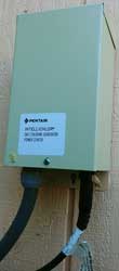
|
15 Volt DC power supply for Chlorine cell.
|
 |
iCHLOR Salt Chlorine Generator (SCG)
Nothing turns on probably because the 10A automotive blade
fuse is blown and there's 30 VDC across it.
22 to 39 VDC is the voltage range, according to the
factory, for the output of the transformer box with the
iCHLOR is disconnected. I expect this is the same as
the voltage across the blown fuse when the iCHLOR is
shorted.
|
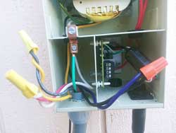 |
The pump is running for all these
photos. Note the green LED on the PCB is NOT on.
The 10 Amp blade fuse was blown and removed.
The voltage across the fuse terminals is 30 VDC.
The manual says it should be 15 VDC.
The transformer primary wiring is correct for 240 VAC.
i.e. the two windings are connected in series as per the
instruction manual.
Line (Black) - Transformer (Yellow)
Transformer (Black) - Transformer (Violet)
Line (Red) - Transformer (White)
There are 4 ways to wire between the Control Panel Output
(CPO) and the iCHLOR Transformer Input (iTI).
Table of voltage across fuse for the different
connections:
|
iTI
120
|
iTI
240
|
CPO=120
|
15
|
7.5
|
CPO=240
|
30
|
15
|
The control panel to transformer wiring should not cause
this problem. Maybe the 30 VDC reading is because of
no load?
Maybe the iCHLOR cell needs cleaning?? This is
almost certainly the problem. The pool man says he
as used Muriatic acid (Wiki)
to clean the iCHLOR cell.
The "pool man" knows chemicals, but has not clue about
electronics.
He says there are a number of pools with the iCHLOR system
that have the same problem in our area. Maybe this
is a lemon product? Let me know.
|
4129493
Swimming pool chlorinator system, Michael
R. Tighe, Hugh
L. McCutchen, Eltech
International, 1978-12-12, - "...utilizes a membrane type
cell having opposed catholyte and anolyte chambers including a
cathode and an anode member, respectively, disposed in a close
spaced relationship to each other and separated by a
substantially hydraulically impermable cation exchange membrane.
"
20100250449
Inline chlorinator with integral control package, heat
dissipation and warranty information accumulator, Kevin
Doyle, Bruce
Johnson, Keith
Shulte, Pentair
Water Pool and SPA, 2010-09-30, -
Water Damage
Kitchen
Early in 2016 the dishwasher blew a hose and flooded the
kitchen overnight. Discovered the next morning. The
house plans are dated April 1991 and it was constructed about
1992, so is 24 years old. A new replacement dishwasher was
improperly installed and the right side of the door hit the
adjacent cabinet. This caused the door to be cockeyed and
twice it flooded the kitchen floor overnight. Some months
later there were bubbles in the vinyl flooring. I looked
into a repair, but it soon became apparent that the bubbles were
growing in size and number. A new vinyl flooring material
was chosen but the store suggested that we contact our
homeowners insurance company so that was done. A handyman
here for something else just used the tip of his pocket knife to
make a very small hole in the top of the largest bubble and when
he pressed it down water came out.
The new dishwasher has a catch pan under it, but I need to find
out how it is drained. Just having a catch pan under the
dishwasher will not do any good if a hose fails.
The insurance company sent someone who tested for water using a
hand held moisture tester (see below). He was able to map
out the area of the floor were there was moisture under the
vinyl floor and it matched pretty well were the water had been
standing from the dishwasher. You would think the vinyl
flooring would be water proof, but I think that the seems allow
water to get underneath and the particle board is like a
sponge. Or maybe the water gets underneath the particle
board and capillary action allows it to move many feet
horizontally.
I got some moisture test meters. I'm thinking it may be a
good idea to test the house annually or more often. Also got
some water alarms and am thinking how to make the house more
resistant to water damage. It seems that water loose
inside a house is extremely destructive. That's a poor
design. It's just a question of when, not if, you are
going to have a water leak, either in the supply plumbing or the
drain plumbing.
For almost two weeks someone would come and use their moisture
meter along with the slide hammer to test the moisture.
Once it's dry there will be a test for spores/mold.
4-IN-1 Pin/Pad RH Moisture Meter

|
This meter has displays for Moisture,
temperature and humidity.
The moisture can be read by sticking the two pins into
wood or using the two metal plates on the back surface by
sliding the meter over the floor. This is a new $80
unit from eBay. It does not have the no electrode
"pinless" feature that is on the Protimeter tester below.
|
Protimeter
Moisture Measuring System (MMS)
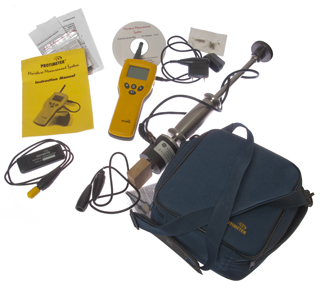
|
The professionals used Protimeter brand
moisture meters, much newer than this older one from eBay.
Protimeter Moisture Measuring System LH22-036 &
Accessories
Included are the:
POL5800 Plus (LH22-036) meter
POL 4750 Hygrostick hygrometer humidity 2-pin probe
(plugged into top of meter)
BLD5802 Hygrostick extension cable
BLD5060 Moisture probe (plugged into side of meter)
BLD5018 Deep Wall Probes (?missing)
BLD5804 Surface temperature sensor
BLD5086 Cal check device (?missing)
INS5800 yellow cover instruction book
BLD5055 Slide Hammer 2-pin Probe
??? Carry bag
??? CD-ROM for extracting data from the Plus version of
the POL5800
Note the POL5800 has an inductive test method where on the
back there are no electrodes. You can hold it at a
45 degree angle and just rub it on the floor to detect
moisture.
|
The next step in the recovery is to bring in about a dozen fans
and dehumidifying equipment. The kitchen was walled off
using Zipwall poles. Because there was moisture under the
floor in the crawl space a U.S. Products air scrubber was
connected to a vent and nearby vents were blocked off so that
there would be air movement to dry the sub floor. All wet
insulation was removed.
The air movers and dehumidifiers are aimed at drying the
kitchen. The HEPA air filter is to remove spores (Wiki) that
might be caused by mold (Wiki,
hidden).
21 June 2016 - I found the Zefon
air sampler, but didn't see what was used. The
samples are sent to a lab for analysis.
This web page suggests that the air samples are meaningless: Is
Testing for Moulds Necessary? - "...remediation of water
damage, the stress is placed on correcting “damp” and not on
removing mould."
EPA
- "Standards or Threshold Limit Values (TLVs) for airborne
concentrations of mold, or mold spores, have not been set.
Currently, there are no EPA regulations or standards for airborne
mold contaminants."
EPA - A
Brief Guide to Mold, Moisture, and Your Home.pdf -
removing the moisture is the key, not much to do about mold
itself.
After drying and testing, prior to bids for rebuild.
Fig 20

|
Fig 21
 |
Fig 22
 |
Fig 23
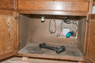 |
Fig 24

|
Fig 25
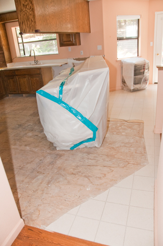
|
Fig 25
 |
|
|
8 July 2016 Kitchen Sink Faucet
Fig 30 The existing faucet was broken by
moving the
copper pipe too much by the water damage people.

|
Fig 31 New Pioneer 2LG106H-BN faucet
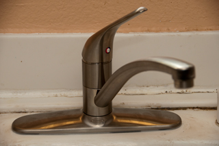 |
Fig 32 The old broken faucet.
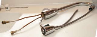 |
Fig 33 The refrigerator water supply has
been relocated
so that it can be seen and turned off easily. Note:
instead of
using copper pipe PEX (Wiki)
was used.
Note vertical divider to left of refer space, removed
in Fig 34 photo at right.
 |
Fig 34 At the very left the drywall has
been trimmed so that
there's wood at the left edge. The divider at the
left of the
refrigerator has been cut away to allow access for the
Sheetrock work
 |
Fig 35 after drywall work done - before
painting
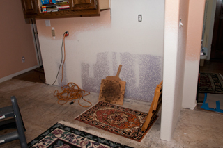
|
23 Aug 2016 Repairing stove island
cabinet
Was not able to get a contractor to repair the stove top
cabinet, so am doing it myself with a handyman.
A table was fabricated using 2x4 and plywood that is 1 foot high
and covered with a blanket to keep from scratching the
cabinet. The stove top island cabinet has been laid on
it's back on the table (the rear protrusion of the counter top
is off the floor). This way the cabinet can be repaired
with the Corian (Dupont)
counter top in place. The temporary 2'x4"x6" sleepers have
been removed (sitting in center part), the bottom 5/8" particle
board floor removed and the lower front rail (edges the floor)
removed, the right side of the dishwasher opening has been cut
back by 3/4" to add clearance on each side of the
dishwasher. The new 3/4" plywood on the right is just
sitting there and will make a new floor in the space that was
formerly used for the never used trash compactor.
Fig 1

|
Fig 2

|
Fig 3 4x6 sleepers ripped to height to
bring top of counter to
same height as existing counter top.
Looking into how to water proof sleepers.
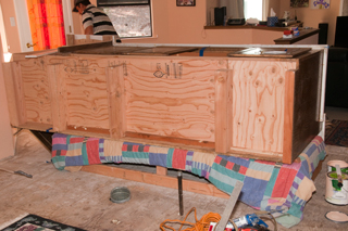
|
Fig 4 mending the Corian counter top
There is a strip of Corian underneath the joint.
A stick wedged between the floor and that strip clamps the
far end.
Later today the surface will be smoothed.

|
|
|
12 Sep 2016 New Cortex
Plus Luxury Vinyl tile Amilfi Grey SKU 50LVT102 Floor
installed
13 Sep 2016 - floor to wall moldings reinstalled as well as most
toe space moldings, except the one in front of combined stove
top and fan in case the installer needs access.
Fig 10
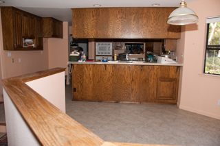
|
Fig 11 Custom wood transition between
hardwood and kitchen was made to
replace the broken one.
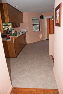 |
Fig 12 New dishwasher will be reinstalled
tomorrow.
 |
Fig 13 The trash compactor has been removed
and the space
will become more storage. The desk has been made
freestanding.
 |
|
|
Kitchen Sink
A few years prior to the dishwasher problem the drains under
the sink leaked causing the cabinet underneath to get very
wet. This was caused by improper installation of the drain
plumbing. The solution was to have a plumber re-do all the
under kitchen sink drain pipes.
23 Oct
2016 - new GE Dishwasher Water Leak
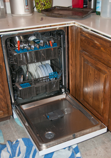
|
I've been told that the silverware in the top basket can
keep the door from closing.
|
A few weeks after almost getting the kitchen back the new GE
dishwasher dumped water on the floor.
Model: GDF570SGFWW, s/n: MF749137B
The local GE dealer came the next day and tried out a number of
ideas, all of which were negative, i.e. they could not figure
out the cause of the leak, but did confirm a leak.
Although the leak they saw was much smaller than what happened
on the night of 23 Oct. Some of the things looked for:
* That one of the propellers was stuck and squirting water at
the door seal. (both propellers are free).
* That the filter screen was blocked. (It was lifted out
and appeared very clean).
* That the drain was blocked. This was tested by removing
the vacuum breaker top cover at the back of the sink and
removing the cap. Then a drinking glass was placed upside
down. (The drain worked as it's supposed to, i.e. no
blockages).
In the past one of the failure modes of the GE dishwasher was
that you could hear it running but there was no water sound,
i.e. no water was being allowed in. This was confirmed
after the door was opened and the inside was dry. In order
to get it working again it was necessary to turn off the breaker
for a few minutes and then restarting the dishwasher. My
guess is that the firmware has a failure mode related to the
water inlet solenoid. Note another failure related to that
solenoid might allow more water to enter than intended and if
the water level got above the lower door seal the result would
be what I've seen in all three instances of massive water
flowing out of the dishwasher.
7 Dec 2016 New
Bosch Dishwasher
The appliance store, after three complaints of the new
replacement GE dishwasher pumping water on the floor, gave us a
full credit toward another dishwasher. Note it pumped
water on the floor while the two technicians from the local
appliance store were here working on it!
After a lot of searching I discovered the Bosch AquaStop® system. "If a leak has
occurred, it shuts down operation and automatically pumps out
water to avoid contact with the floor. Now it even works
24/7 and can turn itself on." If any part of the dishwasher
leaks water inside the unit (either fresh water or waste water)
the water will end up a catch pan at the bottom of the
unit. Any water in the catch pan closes a valve at the
base of the dishwasher stopping any further leaks. It also
uses the pump to send that water to the drain. They also
offer a clothes washer with this same system. This will
solve the common problems, but not all problems. Don't
know about a refrigerator.
The model number is SHX68T52UC.
Some settings can be changed using On/Off, A, B, C and START.
Intensive Drying:
Press: On/Off to turn on
Press and hold "A" (Normal) and press START until the display
shows d:00, then release both buttons.
Press "A" (Normal) until the display shows d:00.
Press "C" (Rinse) until the display shows d:01 (Intensive Drying
is on).
Press START to save setting.
Small hose is water supply.
Larger hose is drain.

|
photo has A, B &C labels added.
Which buttons are A, B & C varies with model number.
|
Master Bath

This was a problem first noticed in 2012 when water was
dripping from the breakfast nook ceiling light fixture.
But drilling a hole near the outlet box in the ceiling and then
expanding that hole until it was about 5' by 3' it was
determined that the master bath tub overflow drain was not
properly installed allowing some (but not all) of the overflow
water to leak out into the house. Notice water stains in
ceiling. The leak was there for a long time before it was
discovered.
I made many appointments with a plumber to fix this but he was a
no show. It took over a year to get the plumbing
fixed. Then a Sheetrock repair, then painted. I
wanted to add a catch pan and drain to the outside, but there is
not a standard way to do that. But there should be.
Hot Water Heater
When the hot water heater failed there was no leak, but that's
not uncommon. So got a catch pan designed to be under the
hot water heater to catch water in case it overflows. The
pan outlet needs to be routed to someplace where the water will
not do damage.
Clothes Washer
The laundry room is upstairs, where it makes sense in a two
story house since the bulk of the laundry comes from bedrooms
and bathrooms that are upstairs. There is a metal catch
pan under the clothes washer, but I don't know if or how it
drains.
Maytag Front Load
Washer
Door would not open and unplugging to reset did not restore
operation.
In order to open door pull string inside detergent
dispenser. It's hidden below the removable parts.
Not economical to repair because of very expensive repair parts.
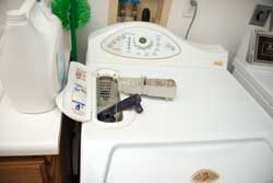
|
Green Pull fiber to open door.
Note hot and cold water supply and drain box.
If a drawer was installed under new washer the above
valves would be hidden.
That's a problem if you need to shut them off in a hurry.
|
Bathrooms
The downstairs half bath floor was recently replaced because
the vinyl had shrunk maybe an inch from the wall. Not sure
why, maybe because the vinyl itself shrunk or maybe because the
glue used to attach it caused the problem. The flooring
company checked using a moisture meter over the old flooring
before quoting the job because if there was moisture under the
floor that would need to be fixed before the new floor could be
installed. The floor was dry so not a problem, but
it could have been.
Water Alarms

SKU 349915-2SBV0 PCK
0309-8335-11903-T-09-04-F
|
eBay title: [NEW] Water Level Alarm Bathtub
Washbasin Toilet Kitchen Anti-overflow Device Wa,
about $11.
Runs on a couple of included AAA batteries. Has
piezo speaker that's easy to hear.
Triggers on clean water but not touching with
finger. Tongue works.
The white plastic is molded to say On and Off but it's
impossible to see, so I've added labels.
Inside there was a wire soldered near the IC but not in a
through hole, just a pad that lifted and tore loose.
Fixed it, but poor construction.
There is an 8 lead IC with only the 4 corner terminals
connected. Also what looks like an
electrolytic cap with 4 leads,
2 of them connected to the piezo element. A very
simple circuit.
PS a water alarm that turns on an LED is worthless.
Ideally there would be a low battery warning, but I doubt
this unit does that, more info later . . .
Water Sensor Alarm using LM380 - might be
similar to this because 4 connections to the audio amp(In,
Out, +, -)?
After searching dozens of water alarms nothing found that
looks like this one.
|
Circuit
Cellar
|
A PIC 12F675 based alarm with low battery
detect, piezo sounder and wireless transmitter.
|
Glentronics
Watchdog Water Alarm
alternate
web page
|
about $10 ea at Home Depot Have
question in to manufacturer about low battery warning.
No low battery warning - replace batteries annually (is
that correct for the new 10 year shelf life batteries?)
|
Electrical Wiring
Thermostat
9 Nov 2015 - It's getting cold and the thermostat is acting
up. I think it's the small wheel that has red and blue
segments that switches between heat and cooling changing
position if the floor shakes. This is a Honeywell T8195b
that uses a couple of mercury tubes and a clock with high and
low timer pegs. It's impossible to set the timer 24 hour
dial to the correct time. So started looking. Found
a review that says Honeywell only warrants their dial if it was
installed by a licensed contractor.
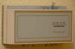
|
Know in center of 24 hour dial should set
time,
but it does nothing. The small wheel with the red
and blue triangles is very touchy, i.e. it can change
without anyone touching it, causing the set temperature
to change.

|
|
two mercury tubes on bi-metal temp. sensors

|

|
Wiring
Label
|
Wire
Color
|
Function
|
C
|
Blue
|
24 VAC Common
|
R
|
Red
|
24 VAC Hot
|
G
|
Green
|
Fan
|
Y
|
Yellow
|
Cool
|
W
|
White
|
Heat
|
O
|
nc
|
not used
|
B
|
nc
|
not used
|
|
So am looking at a White-Rodgers 1F95-1280 Thermostat because
they get 5 star reviews and there's an option in the setup menu
to have the LCD back light on all the time.
The thermostat is in an upstairs hall and it's typically dark
when I go to bed, so having what amounts to a night light is a
great feature.
Carbon Monoxide Detector

|

The AC line is rectified and filtered to provide DC power
without using a transformer. That circuit is under
the LCD.
The brown cylinder that looks like a AA battery is the
Figaro TDS5042 CO Sensor.
The microcontroller is mounted under the LCD.
There are numerous unpopulated pads on both the LCD board
and the main board so there are probably a number of
different model numbers that can be made from the same
boards.
|
After years of service a First Alert Single Station Carbon
Monoxide Alarm Model CO614 started chirping in bursts of
5. The on line manual was no help in understanding why.
But if you unplug the alarm and look on the back (hidden from
view when plugged in) there is a table giving the meaning of the
various chirps:
Sound
|
LED
|
Display
|
Condition
|
4 Beeps
|
Rapid
Flash
|
CO
xxxx ppm
|
CO Alarm
|
1 Chirp/min
|
1 Flash/min
|
bat
|
low battery
|
3 Chirps/min
|
3 Flashes/min
|
Err
|
Malfunction
|
5 Chirps/min
|
5 Flashes/min
|
End
|
End of Life
|
So this unit has reached it's End of Life, but why? That
data sheet for the Figaro
TDS5042 CO sensor has no mention of an end of life.
I have asked them about it. But did not get an answer.
524361
Method of and apparatus for detecting and measuring inflammable
gases, Benjamin C Tilghman, 1894-08-14, -heated Platinum wire
1562243
Apparatus for continuously measuring the combustible constituents
of waste gases, Moeller
Max, Siemens
and Halske, 1925-11-17, - "...containing, at least one of the
elements of the platinum group (including broadly platinum,
iridium, osmium, palladium, ruthenium and rhodium)..."
2904406
Hydrocarbon detection, Pernell
J Moore, National
Lead Co, 1959-09-15, - catalytic filament type
3906473
Method and apparatus for operating a gas sensor, Vine
Harris D Le, Figaro, 1975-09-16, - operates at two
temperatures - cited
by 38 patents
4860223
Carbon monoxide health hazard monitor, Henry
G. Grilk, Rule Industries, 1989-08-22, - "...power supply
which cycles the sensor current at a 60 second high current/90
second low current rate..."
4896143
Gas concentration sensor with dose monitoring, Earl M. Dolnick,
Terry G. Anderson, Quantum
Group, 1990-01-23, - "A tin oxide carbon monoxide sensor is
operated in a manner to exclude effects of ambient temperature and
humidity."
5517182
Method for CO detection and its apparatus, Susumu
Yasunaga, Figaro
Engineering, 1996-05-14, - "...detection of CO with metal
oxide semi-conductor gas sensors..."
7381314
Liquid electrochemical gas sensor, Figaro Engineering Inc., Jun 3, 2008 -
2026 May - Kidde Plug-in single
station CO alarm sounded a double beep, pause, double beep
&Etc. Reading the label says END OF LIFE.
Mfg date: 2015 so lasted 11 years.
WARNING: On eBay
by magnifying the photos you can see that the Mfg date is
often 5 or 6 years old! Best to shop for a current Mfg
date.
NOTE: Most (all?) electrochemical devices (this includes
most batteries) have an expiration date. Buying any of
them used typically means they will need sensor replacement
in order to be functional.

|
|
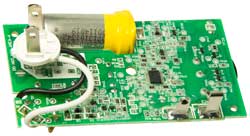 |
Piezo sounder EFM-290ED (East
Electronics) 40mm dia, 3.4 kHz, 9VDC, SPL: 90 dB
Patent ZL200720108836.9
|
Forced Air Furnace Wall Outlet
There are some house wiring anomalies in my house. For
example on a switch plate controlling two lights, when you turn
the switch the wrong light turns on/off.
The wall outlet for the forced air furnace is a combination of
a screw in fuse and a single grounded socket. There are
two ways of installing the socket into the wall plate and two
ways of installing the wall plate into the outlet box. The
house was built with both done wrong. In this case the
outlet for the forced air furnace was installed upside down and
with the socket turned 180 degrees. But two wrongs do not
make a right.
At first I planned to go to the store and find a fused
disconnect outlet plate with the correct orientation, but when
looking at the existing plate it can be seen that the socket is
attached with screws not rivets.
Maybe that was done to allow the installer to configure it
properly, but all the right angle plugs I've seen have the
ground pin at the bottom. That's why NEMA515
wall outlets are installed with the ground pin down in the
U.S.
The fix was simple: remove the two screws holding the wall
plate to the outlet box, remove two screws holding the socket to
the outlet plate, remove the white wire from the socket (then
spend 10 minutes finding the dropped screw (it would have been a
good idea to clean the garage floor just below the outlet before
removing any screws) rotate the socket 180 degrees, reinstall
the two socket mounting screws, reinstall the white wire with
the screw from the floor, rotate the outlet plate 180 degrees
and reinstall it. It took less time to do that than to
write the above.
I've been trying to figure out why a fused
disconnect wall plate is used with a forced air furnace.
One article said that it prevents plugging in other things
which is not wanted since the furnace might use all the
current that one circuit can supply.
Another article said the fuse can be unscrewed by a
service man to remove power from the furnace, but that can
also be done simply by unplugging the cord.
I think there is an electrical code requirement that there
needs to be a way to disconnect a motor that's near the
motor, and that's met by unplugging the cord.
So if you know why the fused outlet let me know.
|
Forced Air Furnace Outlet Upside Down and
Reversed

|
Forced Air Furnace Outlet Installed
Properly

|
Furnace Controller
Feb 2016 - The house was cold because the propane tank was
empty (it's been cold for here i.e. in the 30s at night).
But after the tank was filled the furnace did not start.
In the past the problem has been a burned out ignitor, but
that's not the problem since when powered up the ignitor lights
up and the controller cycles through 3 attempts then stops and
the red light blinks.
The problem is either the controller or the gas valve. I
thought it was the gas valve, and the service techs also thought
that was the problem and replaced the gas valve, but then
discovered the problem was the controller. A way to
differentiate between these might be to measure the output
voltage of the controller with the main gas valve disconnected
(best done with a Fluke 12 or other meter that has a V-Check
load on the voltage ranges) and then compare to the voltage with
the main gas valve connected.
The controller is a White-Rodgers Model 50E47-170.
Circuit Breakers
A Square-D XO Dual 50 Amp breaker failed to power an air
conditioner. Sometimes cycling the toggle on and off would
restore the circuit.
The problem turned out to be that one of the Platinum contacts
was disconnected from the conductor.
Do not
manually turn off these XO series breakers.
Doing so may destroy the breaker.
This may be because of age or the design of the XO
series breakers.
|
Both contacts are in place on this side
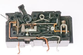
|
The bottom contact is laying on the center
divider.
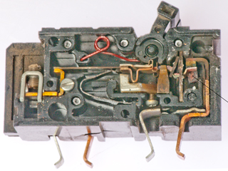
|
Power Line Cords
Old Line Cords
Two lamps were in storage because they did not work.
The antique lamp had a very loose push-on, push-off switch and
the blue lamp was missing the plastic on-off knob.
Fig 1 Two Old Lamps

|
Fig 2 Old Socket
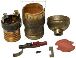
|
Fig 3 Assembled antique socket
The plunger may be upside down.
I broke off a chip of plastic from right side terminal
when removing red fish paper cover.
PROBABLY WRONG ASSEMBLY - fell apart first time
used.
 |
Fig 4 Maybe a better assembly
holds with repeated operations
 |
|
|
Repair
It took only a few minutes to remove the top part of the socket
and replace it with a new one on the blue lamp.
The socket on the antique lamp has a larger diameter (1.5") than
the new sockets (1") so it was necessary to replace the whole
socket. You can see at the base of the lamps in the photo
above the old socket on the left is slightly larger than the
newer socket on the right. As shown in Fig 1 both lamps work,
but . . .
Leakage
After replacing the defective lamp sockets on these two lamps
they were working with the new 3-way LED bulbs. Because
one of them is an antique I measured the AC voltage between the
ground on the wall socket and the metal parts of the lamp and
found 25 VAC. Testing the unplugged lamp showed OverLoad
(infinite) resistance between the two prongs of the AC plug. Meggers operate
at high voltages in order to see leakage currents since it's
very difficult to measure then using low voltages. That's
why the Fluke 87 V DMM
failed to show the problem in resistance mode, but did when
measuring AC voltage.
Cord Replacement
The blue lamp has it's bottom covered with paper so the new
cord will need to be soldered to the old cord at the socket end
then snaked through. The antique lamp has easy access to the
bottom.
Patents
439/666
- electric lamp sockets
200/51.15
- pull string or chain
200/51.16
- push button
200/51.17
- Turn Key (a socket without a switch is called a key-less socket)
no luck finding this patent. Note socket marked Made in U.S.A.
Dead Refrigerator
2022Sep 18: The contents of my refrigerator were warm. It
is maybe a couple of decades old so expected a dead compressor,
but after finding out that there are no equivalent refrigerators
locally and it takes months to get one I called for a repair
estimate. It turns out that the problem was a bad relay,
not the compressor. In the mean time I got a 4.5 Cu Ft
freezer - refrigerator combination and put it in the garage for
soft drinks and frozen meals, butter and staples.
This 4SP is NOT a conventional electromechanical relay (Wiki) but
rather a Positive Temperature Coefficient (Wiki:
PTC) resistor that heats up and it's resistance gets low enough
to allow the motor to start. See patent below. In the same
housing there is a 4TM motor protector that will power off the
motor if it stalls.
Labels: 4SP1001, 2212179, 30 H02R, 437NFBYY, 53 FBH2L
Fig 1 4SP Thermal Relay (see patent below)
terminals 4 and 1 at bottom

|
Fig 2 Sockets 5 & 6 at center.
Klixon 4TM at top (CarbonBrush:
motor protector)
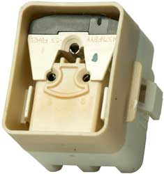 |
Fig 3 I may have broken the PTC disk
when breaking open the case wired between 5 & 6.
But the burn marks were probably caused by overheating.
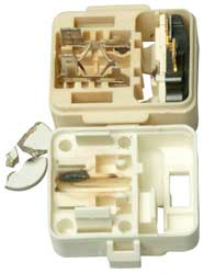 |
Mechanical
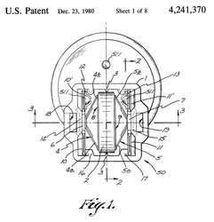 |
Wiring
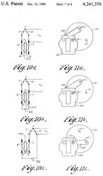 |
4241370 Thermal
relays particularly for starting single-phase asynchronous
motors, TI,
1980-12-23, - |
|
|
5607610
Compact protector, TI,1997-03-04,
- PTC element contacts bimetal strip (Wiki)-contact
arm
|
|
|
6548924
Protective device for a hermetically sealed type
compressor and a hermetically sealed compressor listing
same, TI,2003-04-15,
-
|
The Refrigerator needs to be set to be below 40 deg F and the
Freezer below 0 deg F. The Fluke 87 DMM with
thermocouple probe can help. Also turned on the ice
maker.
Dead Outlet
After the power
failure on 4 Feb 2024 caused by a tree being blown into
power lines which resulted from the Atmospheric River rain
softening the ground, my telephone system was dead. It
was clear that the GFI outlet was dead and the reset button
had no effect. The house plans with a hand customized
overlay by the electrician was of no help in understanding how
the outlets were wired. An inspection of the garage
showed two other standard (not GFI) outlets were also dead,
probably because they were downstream of the GFI outlet.
I cycled all the breakers in both breaker boxes to no avail.
My back was not up to me doing more so hired a
helper. He used a neat trick to figure out which outlet
corresponded to which breaker. It consisted of an
extension cord plugged into the dead outlet and an Solenoid
Electrical Tester (Wiki).
continuity.
can measure voltage or indicate
continuity just by applying test leads: Ideal Vol-Con
61-076 - under $40 used eBay
61-065
|
100 - 600 VAC/VDC
|
YouTube
|
61-076
|
5 - 600 VAC/VDC &
Continuity
|
61-079
|
Same as 61-076 except with
slim line leads(61-081)(4ea:LR44batt)
|
Test
Lead Recall
|
61-092
|
24 - 600 VAC/VDC, Lights
simulate Solenoid scale & vibrator, NCVT
|
YouTube
|
61-096
|
Split-Jaw, Volts, Amps,
Ohms, Continuity - all auto selected (no dial)
|
YouTube
|
Why so many for sale?
It turns out there's a safety consideration because of the
solenoid overheating and/or exploding. See the Fluke
white paper.
Most manufacturers are discontinuing the real solenoid type
testers for this safety reason. Some of the newer
testers have lights arranged like the solenoid scale and
include a shaker motor to simulate the vibration associated
with solenoid operation. A key advantage of the Solenoid Electrical Tester is that you can feel
what's happening and do not need to see the scale since the
vibration is proportional to the voltage level. The
vibration also acts as a warning. Note there is an
operational note of all of the Solenoid Electrical Testers saying something
like to make a connection for no more than 10 seconds and then
allow a 2 minute cool off period prior to using again.
Fluke T5-600, T+Pro, T, T130, T150; Klein
ET250 - probably also work that way, but not clear from
their web pages.
A non contact voltage sensor (Ideal
61-657) should also work.
After removing the cover panel, just wiggling each breaker
will detect the breaker that is not seated.
Patents
1193095
Electrical Measuring Instrument, Hubbard C. West, 1916-08-01 -
solenoid moves for DC voltages up to 30V.
1538906
Potential indicator, Richard
J Parisian, Wigginton
Co, 1925-05-26, -
2501725
Instrument structure for portable testing voltmeters, Otto
A Knopp, 1950-03-28, -
2632785
Pocket type voltage and polarity detector and indicator, Harold
P Knopp, Louise
B Knopp, 1953-03-24, -
Klein ET250
This seemed like a good choice, but it's hard to tell because
the data supplied in advertisements does not seem to cover the
things you want to know.
Ideal 61-657 Non Contact Voltage Tester
This is a Non Contact Voltage Tester (Wiki: NCVT)
YouTube,
6:51 -
Model
|
Range
VAC
|
Flashlight
|
Power On
LED
|
Battery
|
61-627
|
50-600
|
No
|
|
|
61-637
|
24-600
|
No
|
|
|
61-647
|
50-1000
|
No
|
|
|
61-657
|
12 - 1000
50 - 1000
|
Yes
|
Yes
|
2x AAA
|
There's a safety issue with many of these if the battery goes
dead while you are using it. There would be no indication
of a problem and a live circuit would not be indicated.
That's why the newer units have a LED that glows whenever the
unit is switched on.
3919631
Leadless probe, Richard
D Brown, 1975-11-11, - for continuity, not AC voltage
detection
4724382
Testing instrument for detecting alternating voltages in mains
and alternating electromagnetic fields in the vicinity of
voltage-carrying conductors, Hubertus Schauerte, 1988-02-09, -
switching transistor drives Darlington pair transistor to light
LED.
5103165
Insulated, hand-held non-contacting voltage detection probe, James
M. Sirattz, Static
Control Components (Santronics Inc), App: 1990-11-19, Pub:
1992-04-07, - MC1458 Dual Op Amp
5363045
Hand-held non-contacting electric field detection tool, George
G. Martin, Thomas J. Martin, 1994-11-08, - based on 555 IC.
5877618
Hand held non-contact voltage tester, Thomas
M. Luebke, David
L. Wiesemann, Power Products (Applied
Power), 1999-03-02, - five stages of 4069 Op Amps drives
LED & buzzer.
Room Air Filter
Dave Jones on EEVBlog and Fran Blanche have purchased Blue Air
HEPA filters. Fran just posted (YouTube: The
BlueAir Filter Problem) about the
problems she's having with the carbon filter.
I'm happy with my Rabbit Air which
has a nephelometer (Wiki) to
sense airborne particles and it has a photocell (Wiki) to
turn down the speed at night so it's extremely quiet while you
sleep.
A way to see that it's working is by using the DM106 Air
Quality Meter. During wild fires it shows over
300 (PM2.5) while indoors it's reading 3 (PM2.5).
Gardening
Weed Eater vs.
Large Glass Window
2016 - When using a weed eater you can move left to right or
right to left. The front edge of the string can fling objects so
it's always a good idea to go in the direction so that those
objects go away from people or places that can be damaged, such
as windows. The sad part is that I replaced that exact
window because it had internal moisture about a year ago.
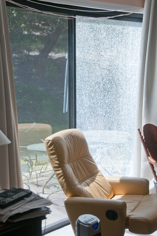
Roll Up Garage Door
Within less than a year there were three failures (Spring,
Rollers, Cable) on this 2-car wide garage door that gets twice
the use as the adjacent single car door. So, I'd recommend
that when any one of these three things fails it's time to
replace all of them.
Roll Up Garage Door Spring (Oct 2017)
When There's a power failure the door can be decoupled from the
motor by pulling down on the red cord. Then the door can
be opened by pulling of the red cord.
CAUTION: The sheet metal edges of the door panels can cut like
knife blades so DO NOT LIFT DOOR PANELS BY HAND unless you are
wearing leather gloves.
But . . . when a spring breaks you can NOT lift the door
because without the counter balancing effect of the spring it's
too heavy. Even applying upward force to the door using a
piece of wood to avoid being cut, and actuating the motor the
door would not lift.
The new springs were installed without lifting the door, i.e.
with the cars in the garage.
When one of the two springs breaks, the one on the right in
this case, the motor is not strong enough to lift the door.
Broken Right side spring
 |
After replacing both springs
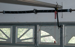 |
Roll Up Garage Door Rollers (Dec 2017)
It was only a few months ago that the springs were
replaced. Should have had the rollers replaced then.
The problem is that when closing the door sometimes stops about
a foot above the floor. The cause was the top of the door
hitting the stop switch.
YouTube: Garage Door
Stops 1 Foot from Floor - you can see the top of the door
tap the stop switch. The problem was worn out rollers.
Old roller without bearings and new Nylon roller with bearings.

Roll Up Garage Door Cable (Jun 2018)
Not long after closing the door a loud noise was heard from the
garage, but didn't know what it was. The next day the door
failed to open. There is an gap at the bottom of the door.
Outside view with broken cable on right

|
Inside view of broken cable
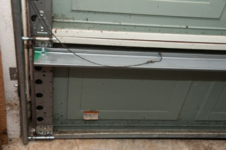
|
PS In the above photo of the broken cable it's resting on a new
brace. The brace was added after someone tried to back out
of the garage without opening the door. The repairmen from
K&T Rising Doors of Ukiah had seen this many times and knew
exactly how to fix it. A much better deal than replacing
the whole door. It's a pleasure to watch workmen who know
exactly what they are doing.
Links
Design News - Made
by Monkeys
UK Hints & Tips: first page, second page,
Repair Brief 1,
Repair Brief 2,
Repair Brief 3,
Sci.Electronics.Repair FAQ
- includng using a scope with a 50 Ohm termination and a square
wave signal generator as an electrolitic cap ESR Scope.
Back to Brooke's Home, Products for Sale, Electronics, Military
Information, Home page
Page created 24 Aug 2001.

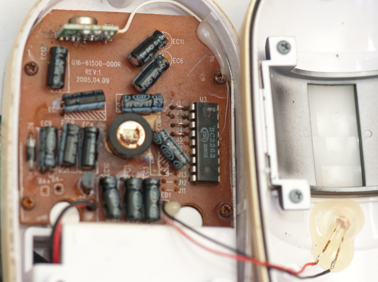


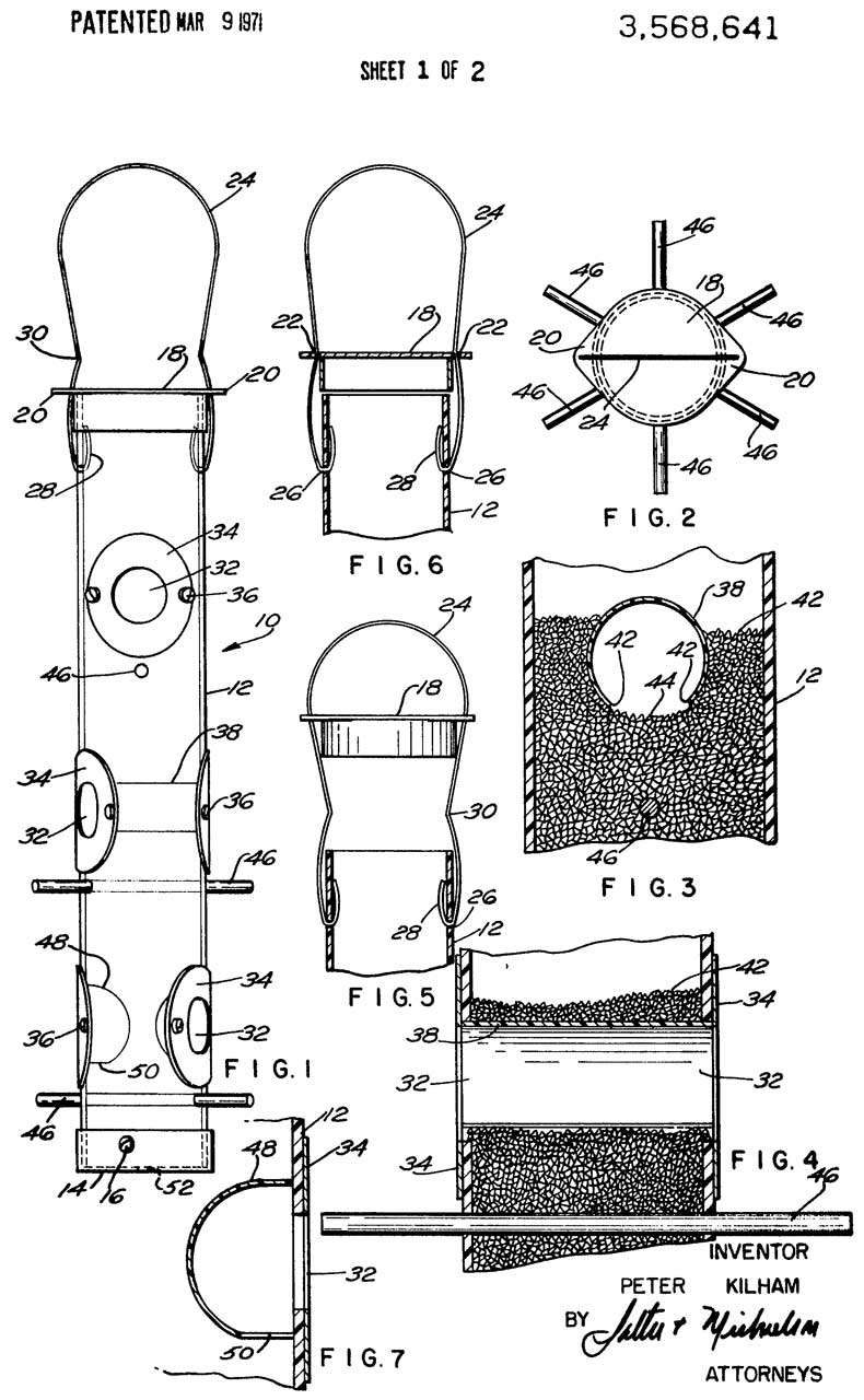


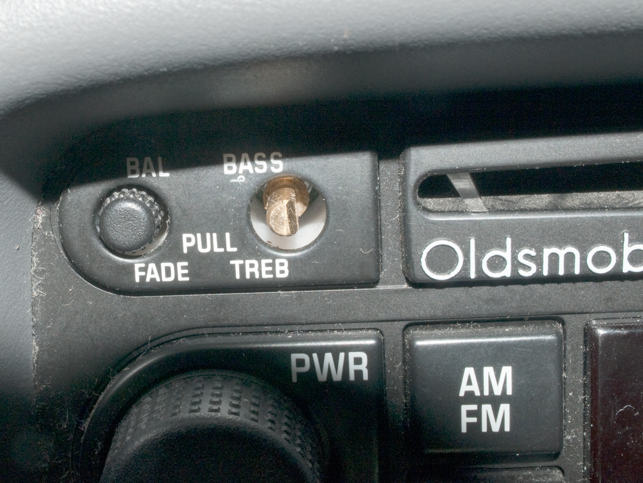
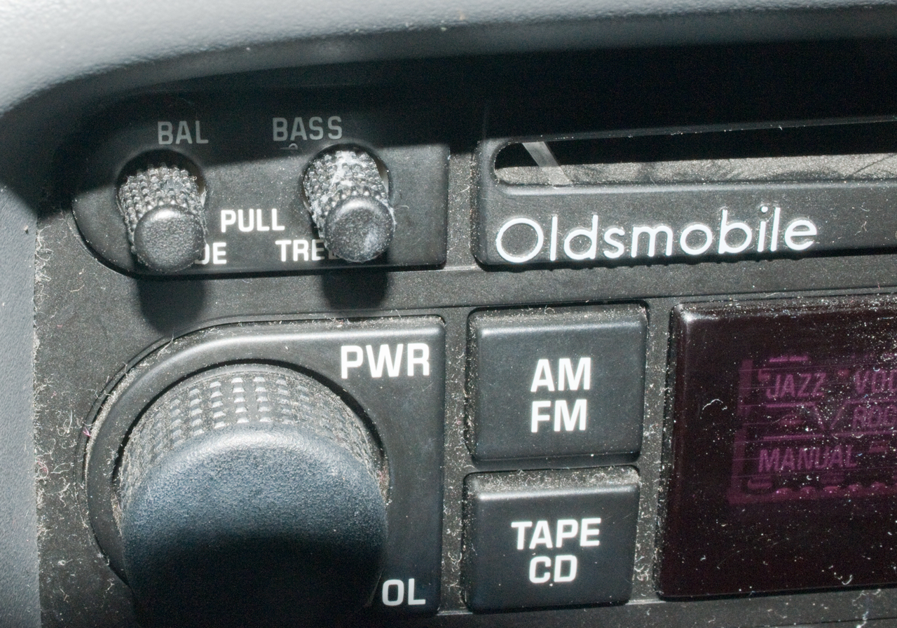
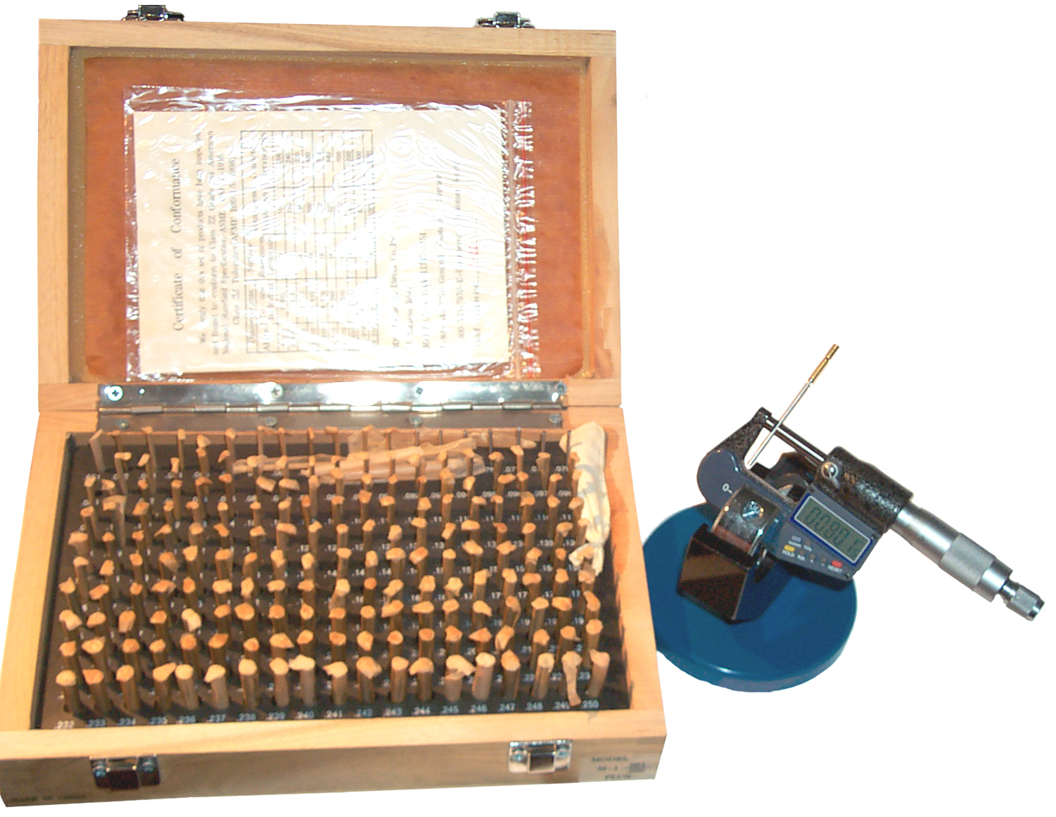

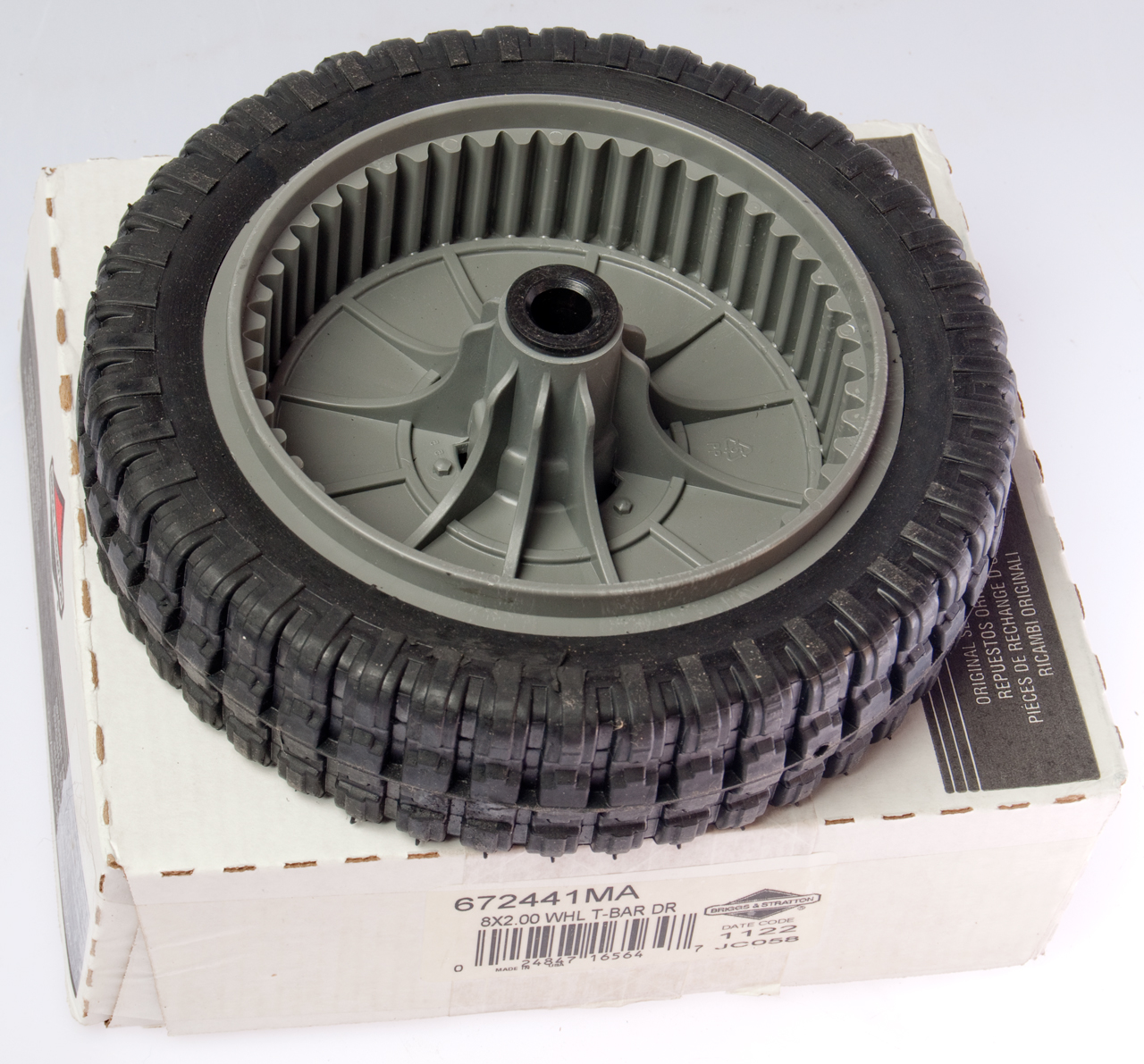


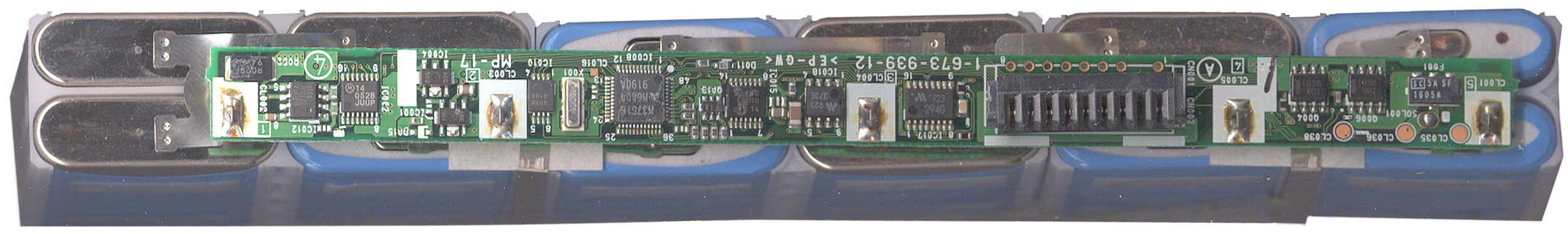
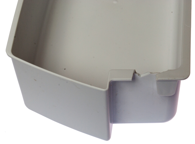

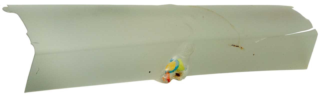
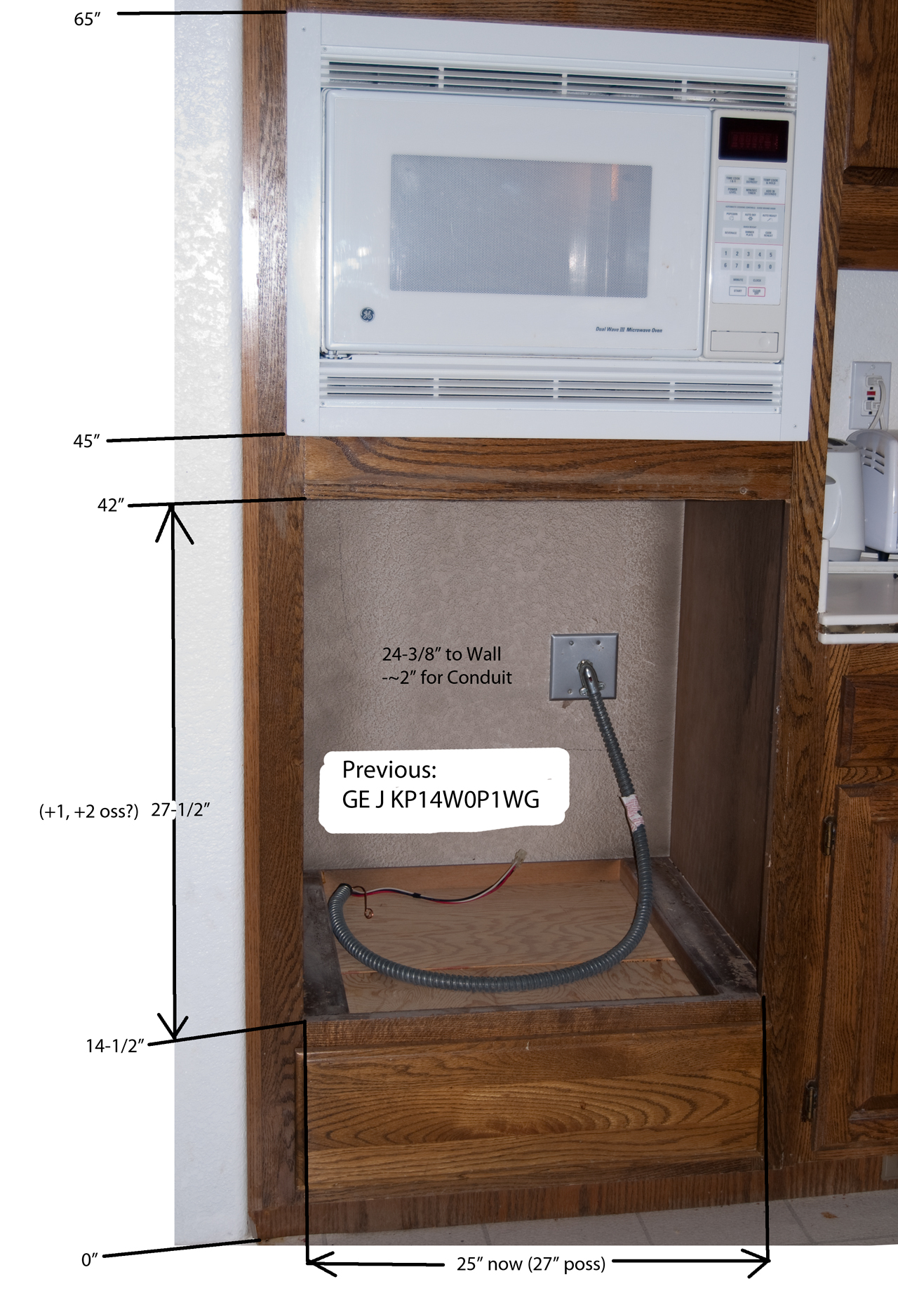

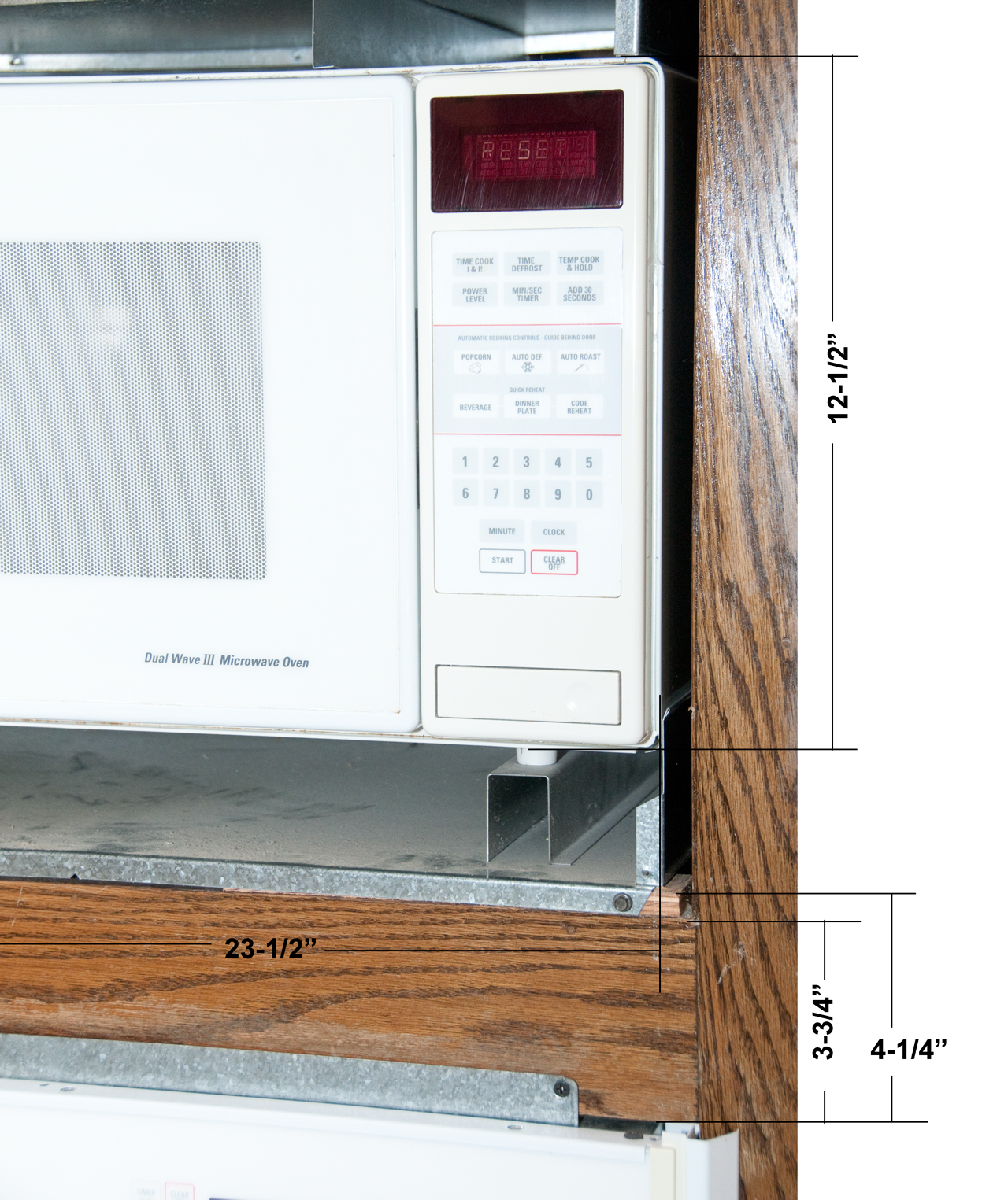
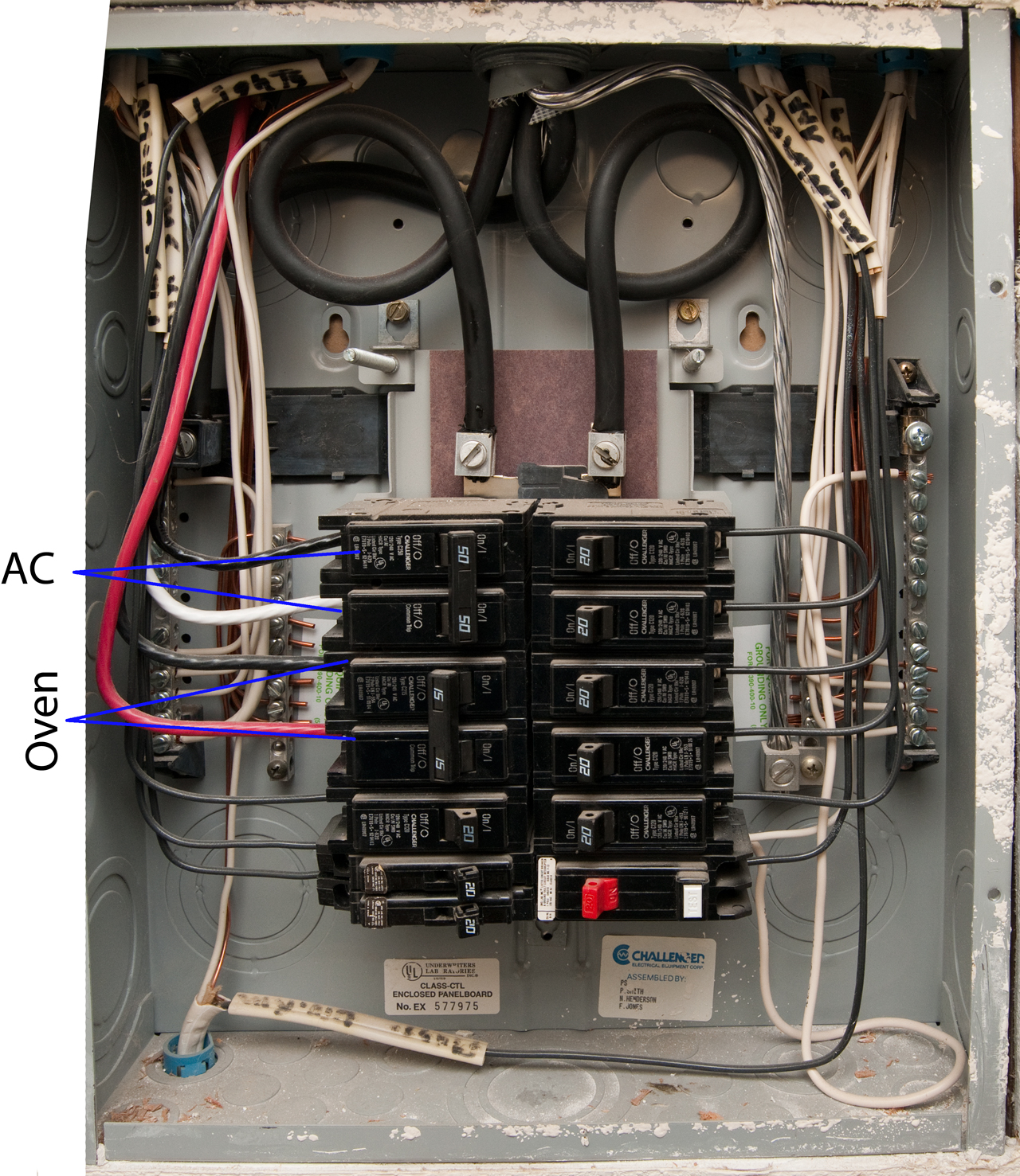


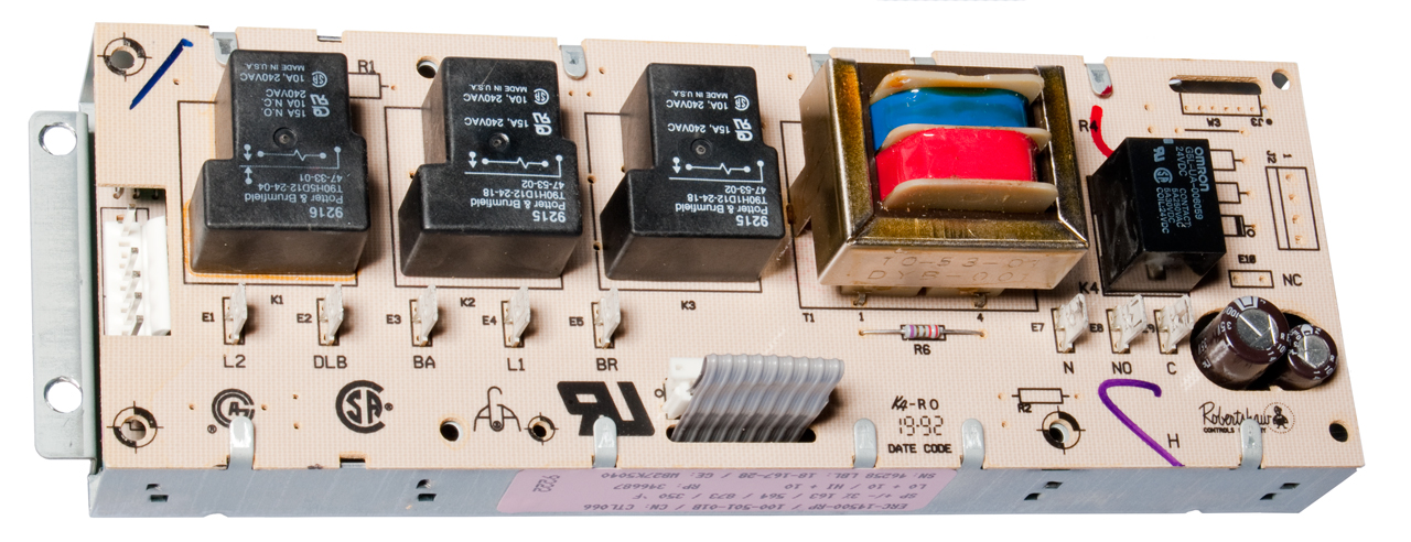
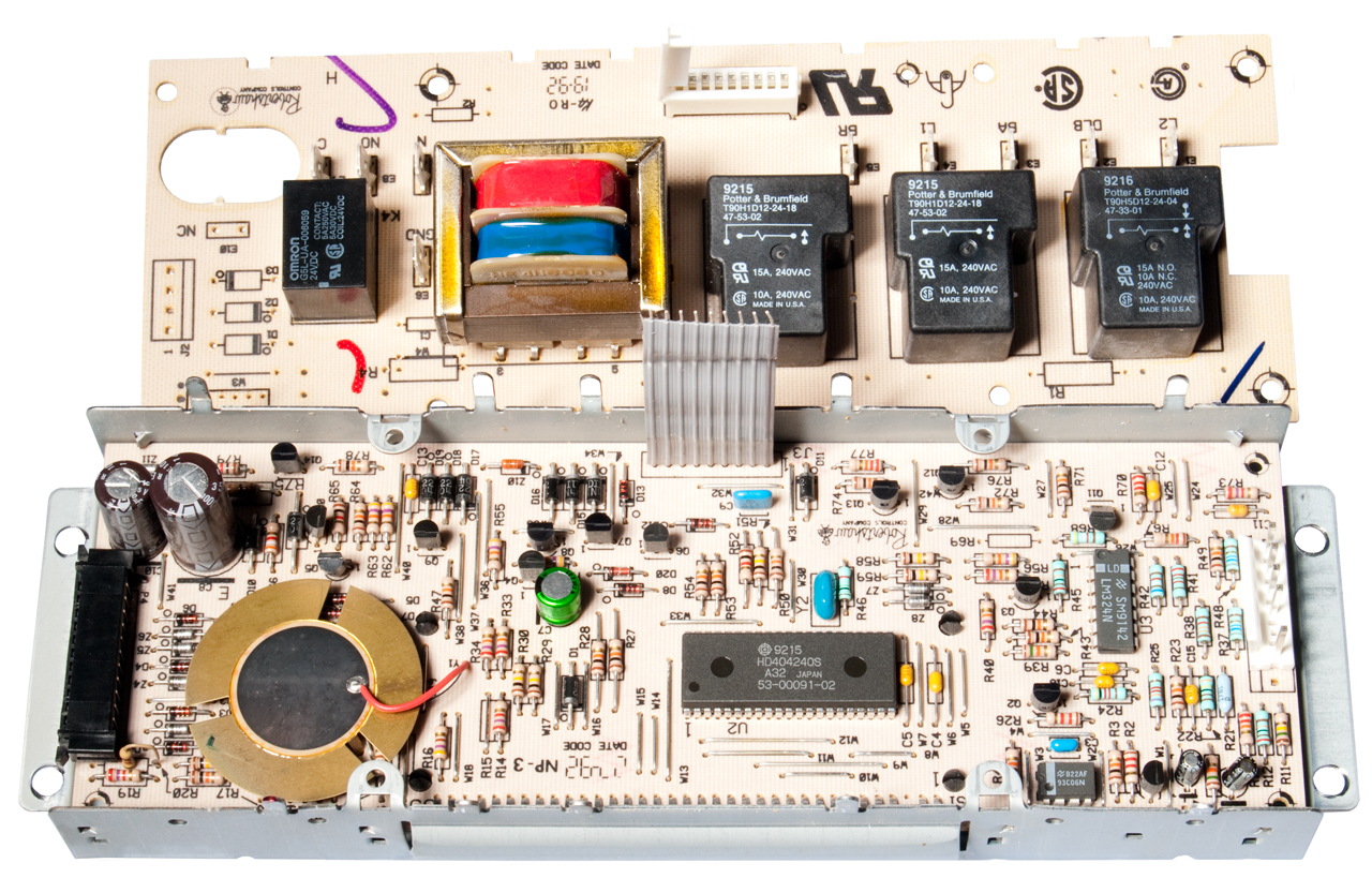
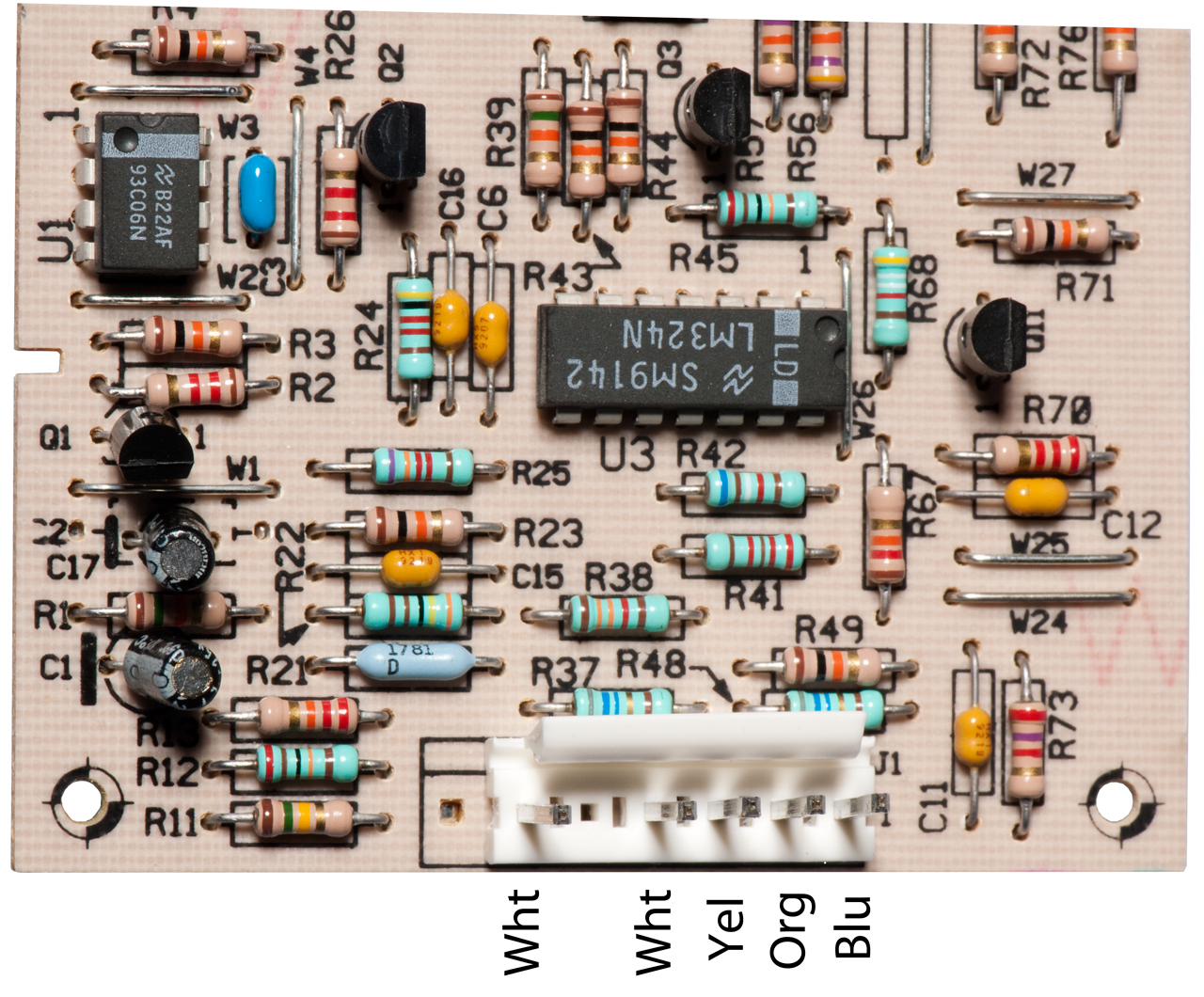
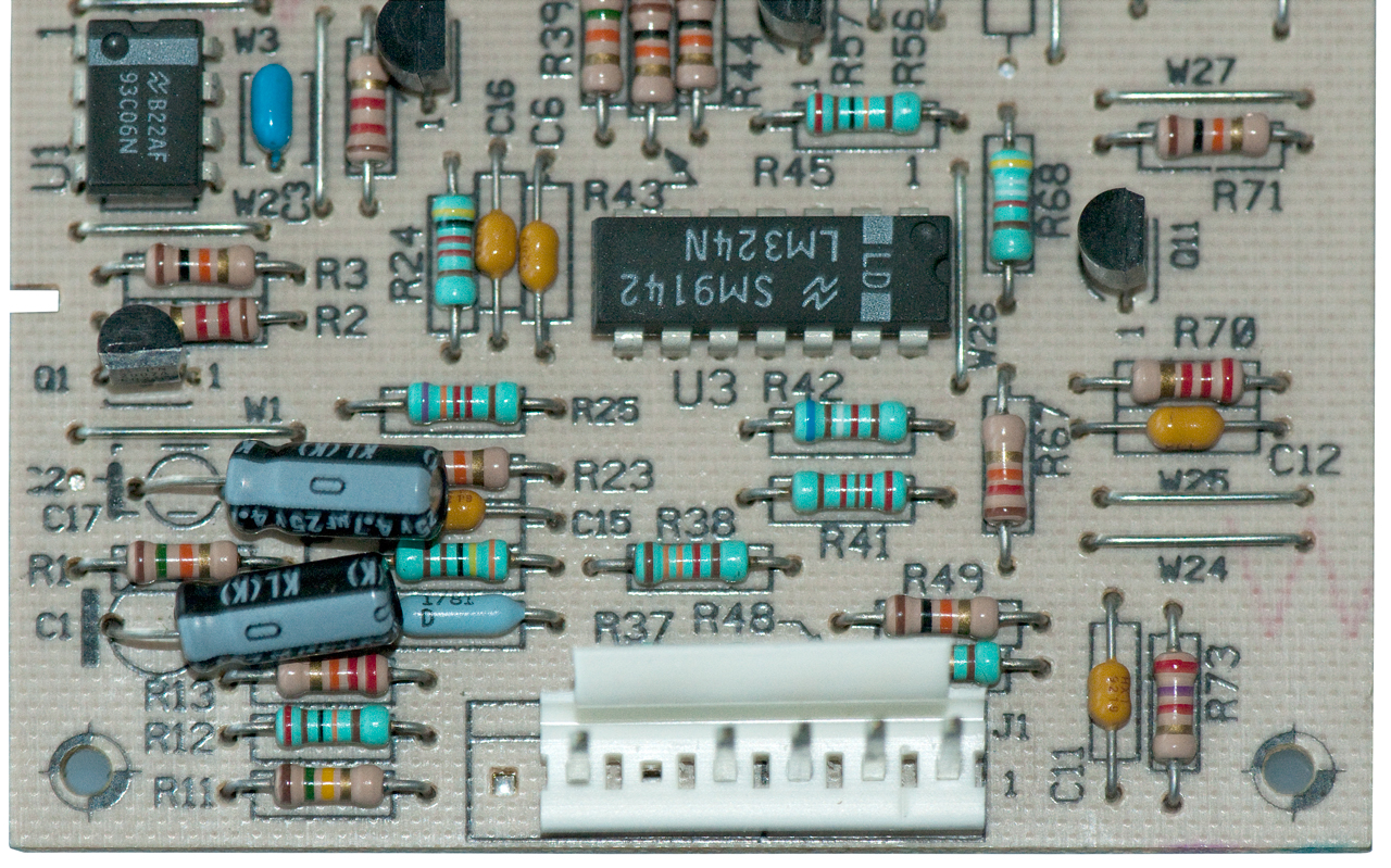
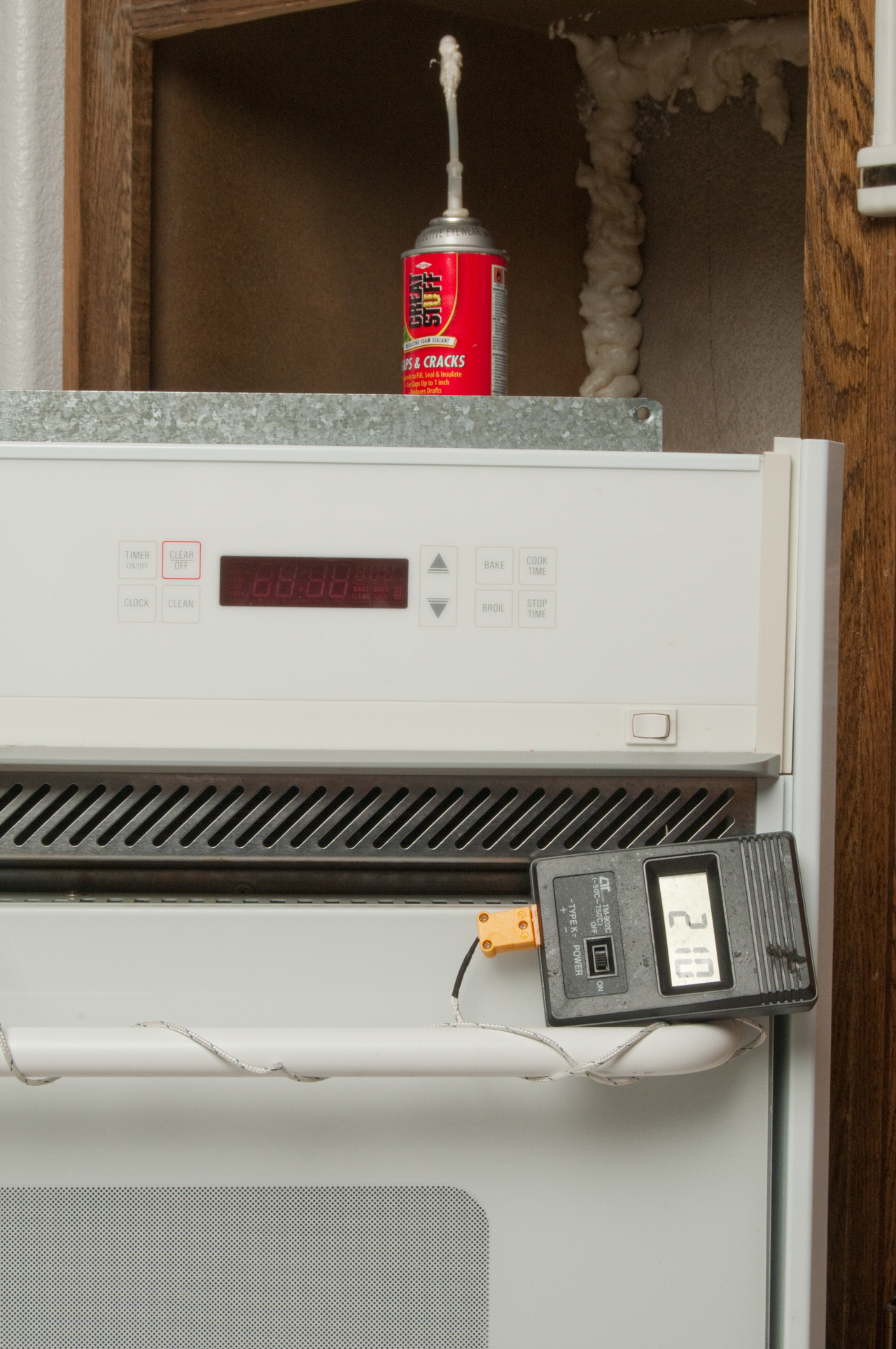

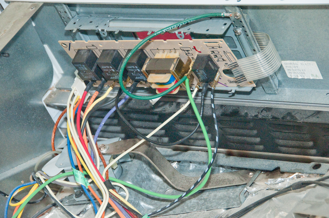


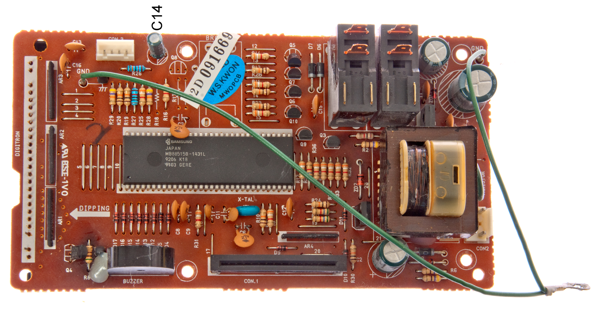
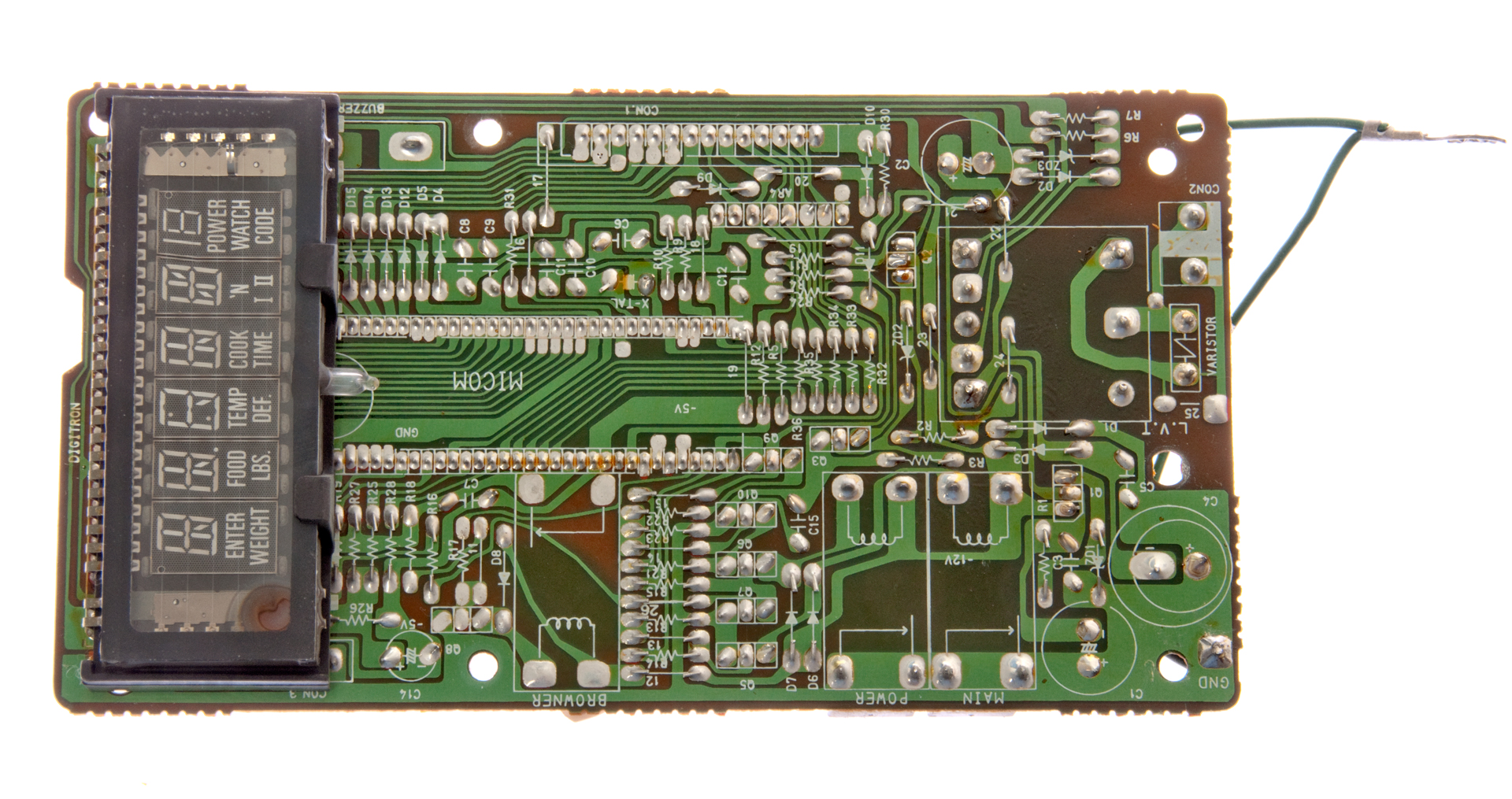

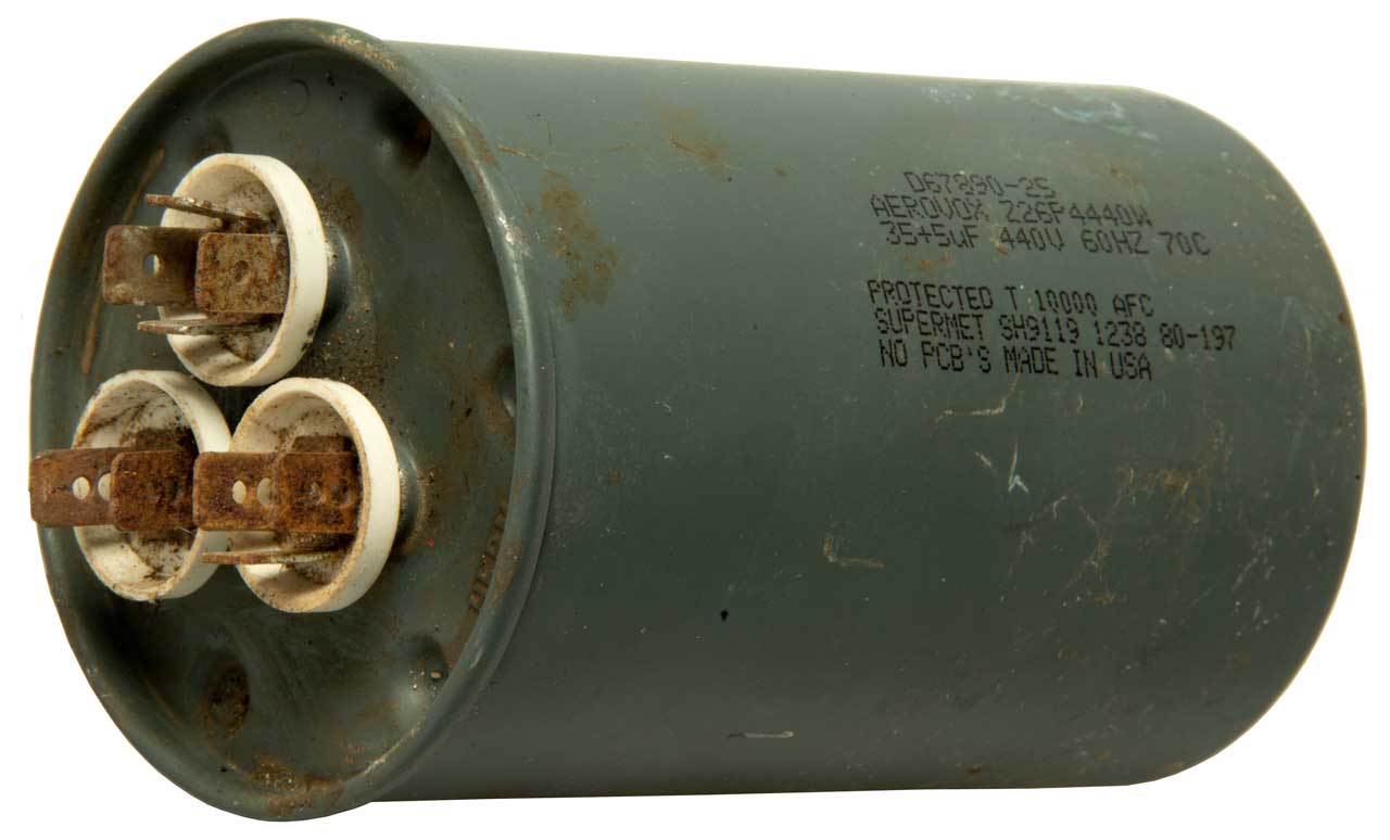


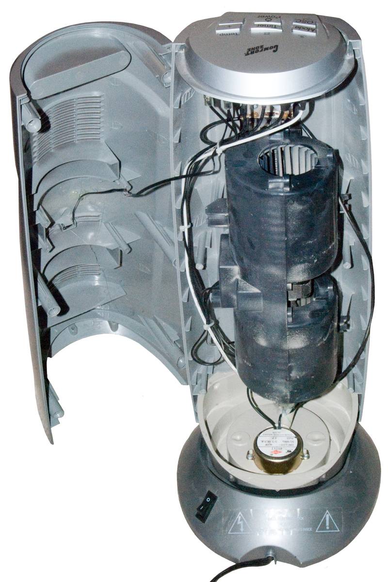
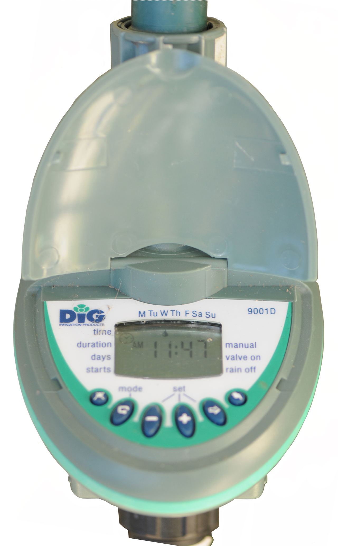
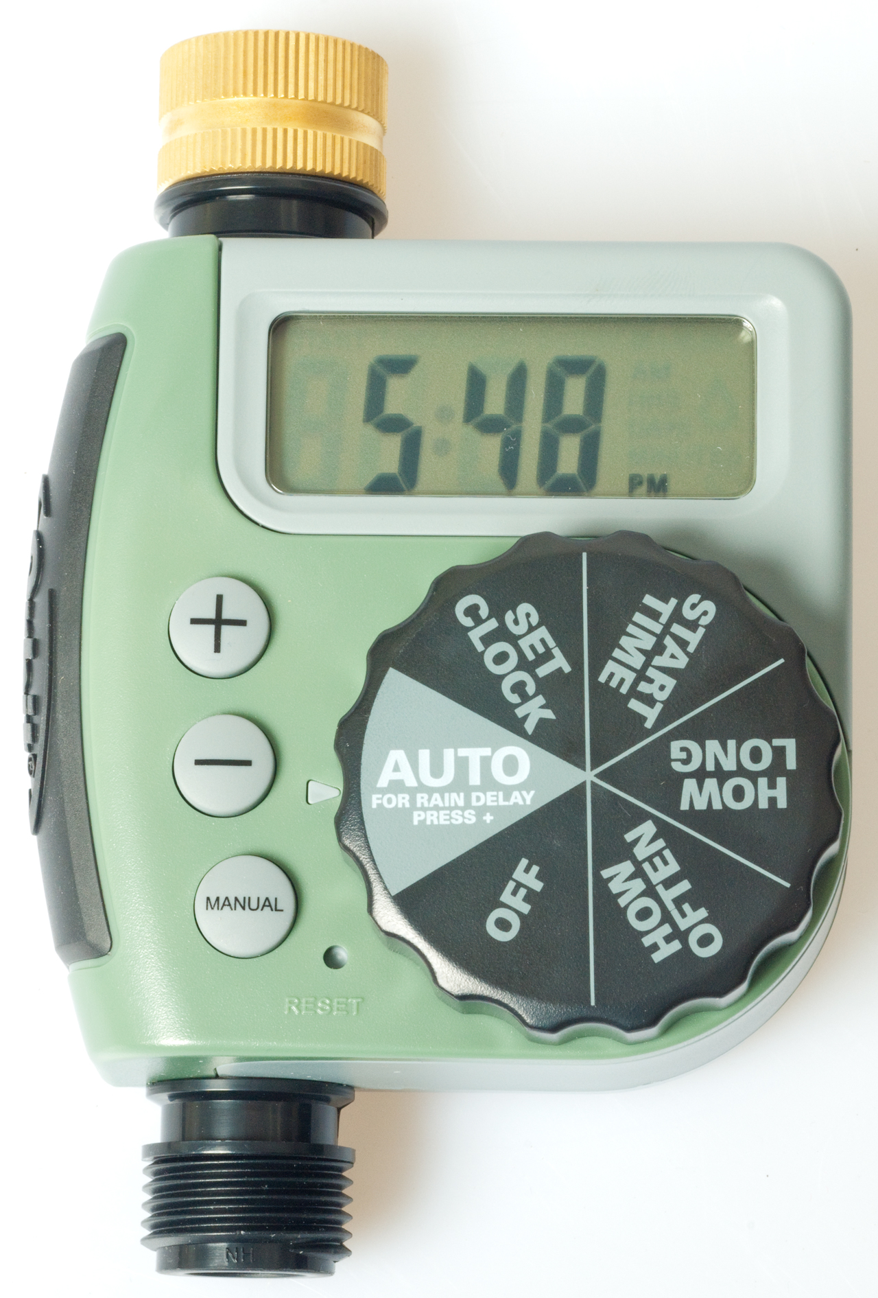

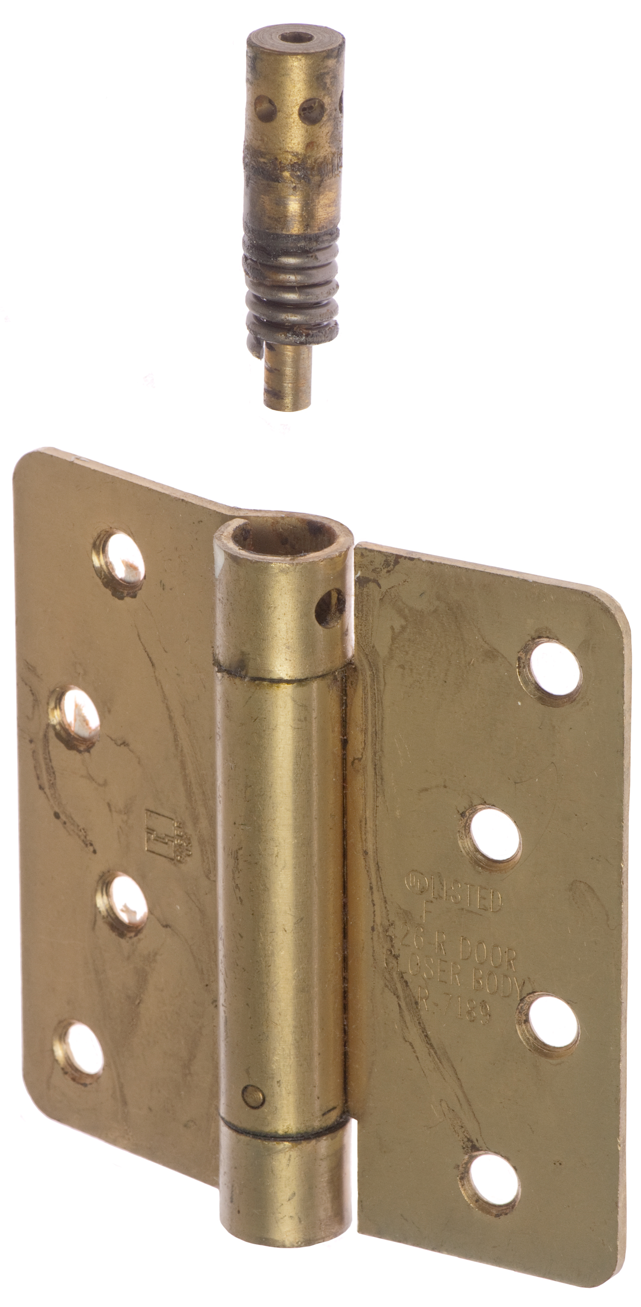
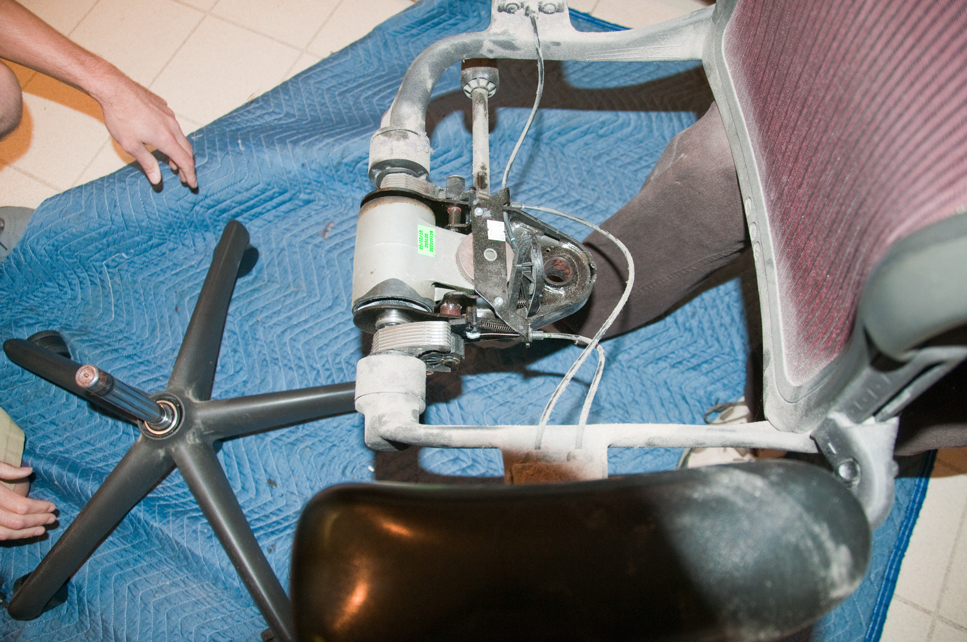
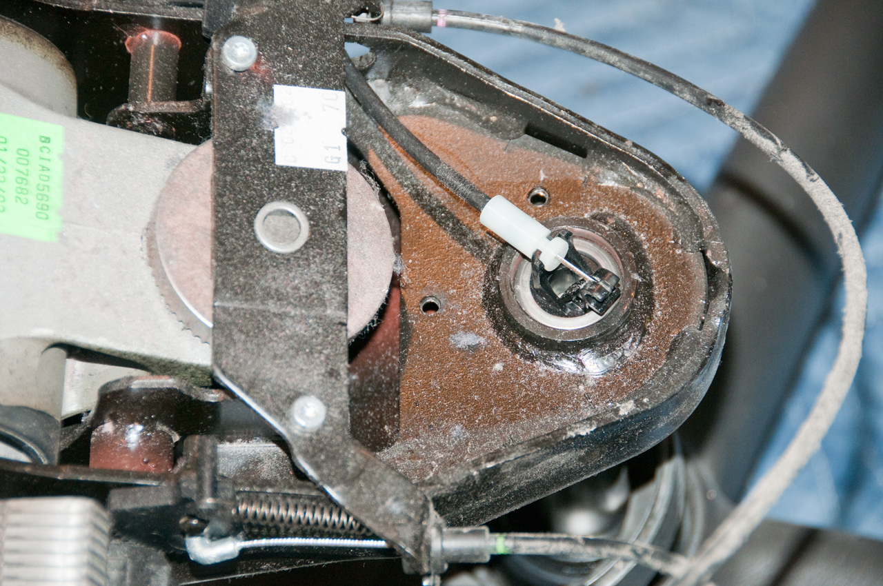


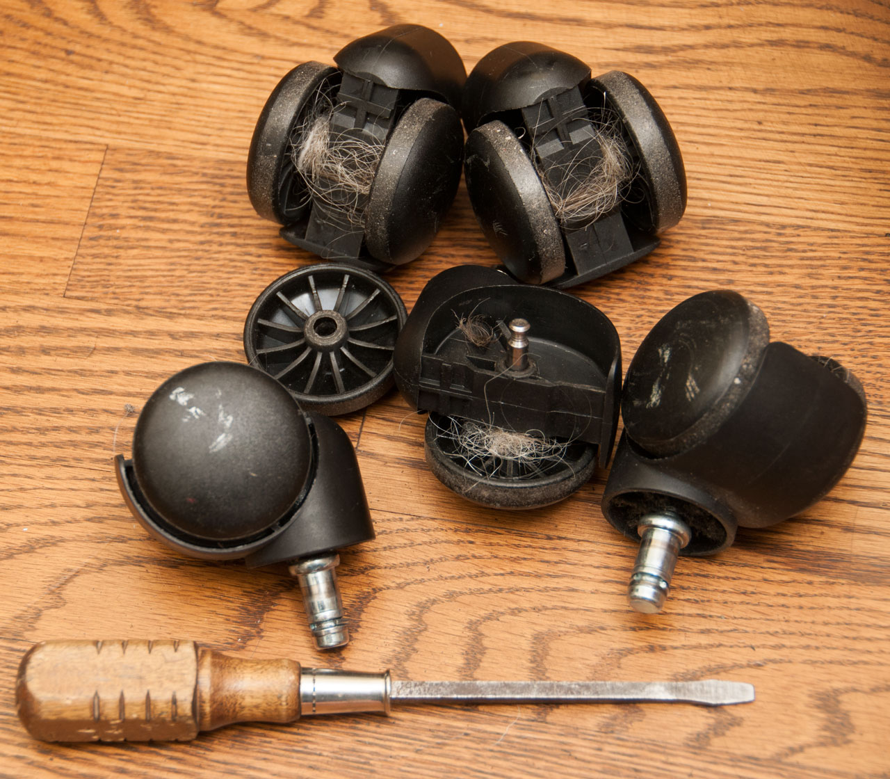


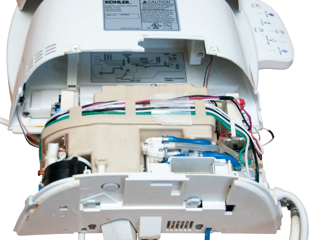
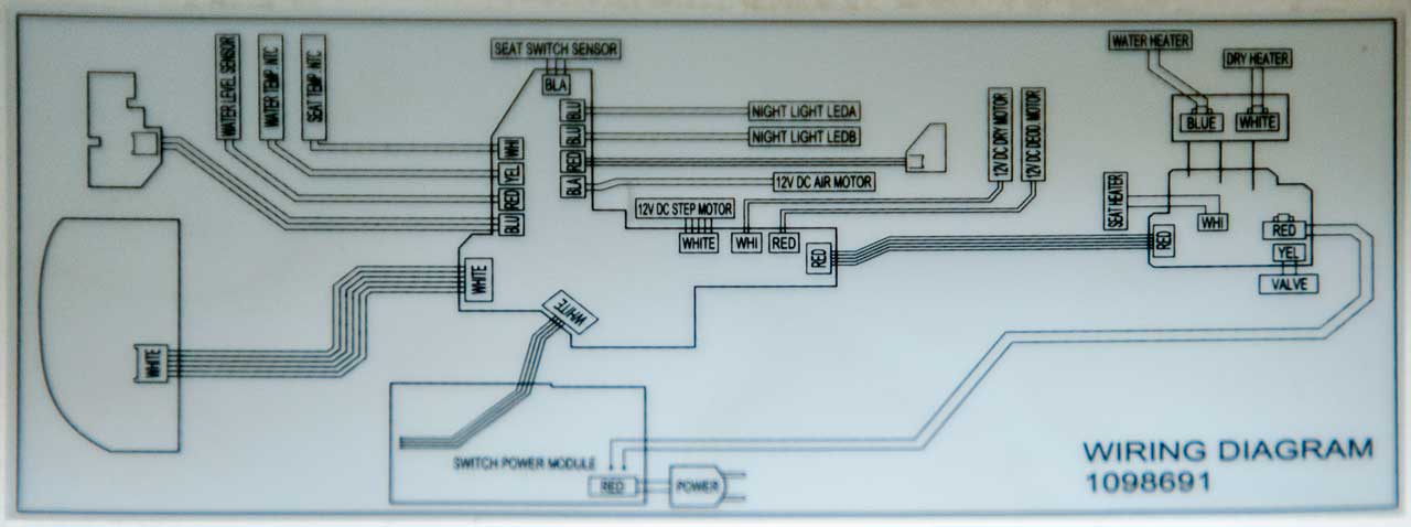

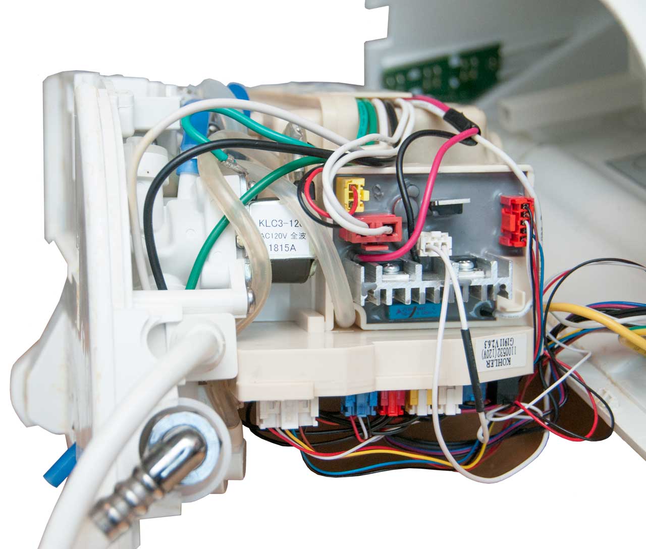


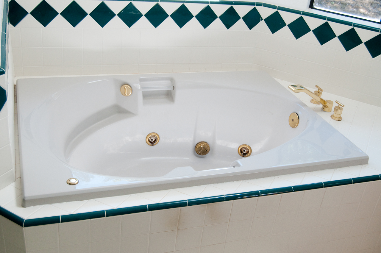


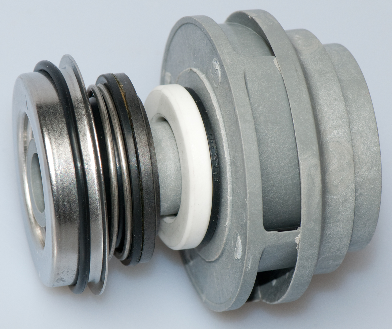


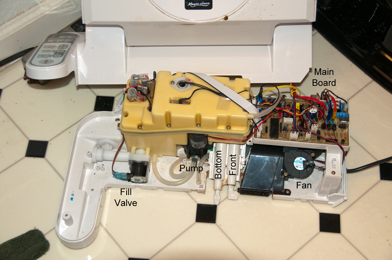
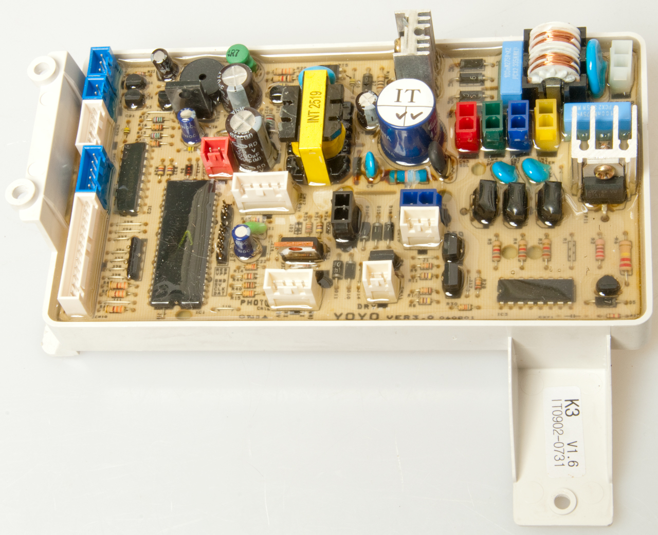
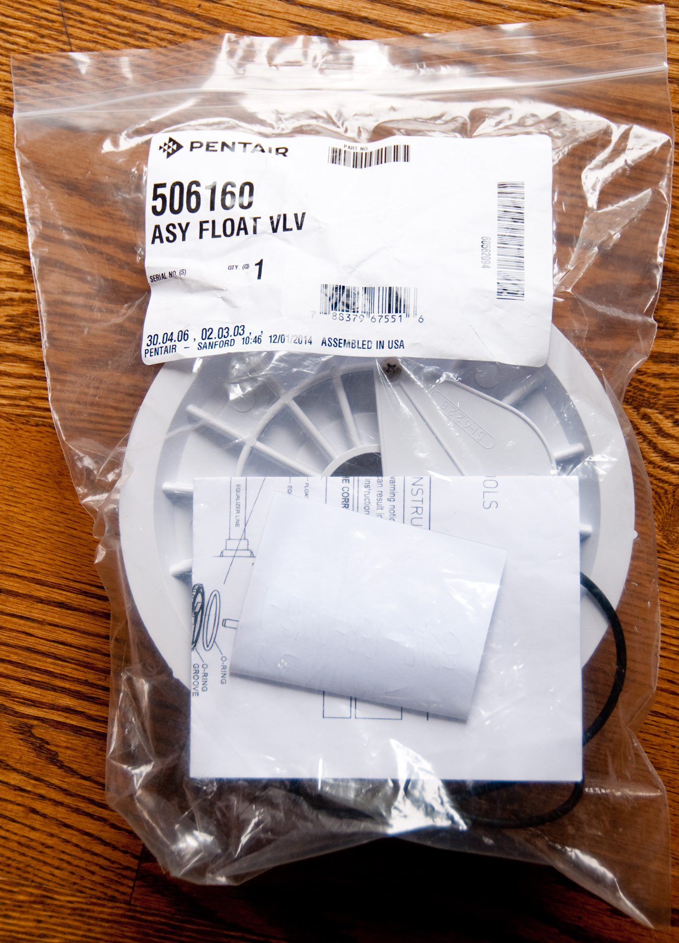
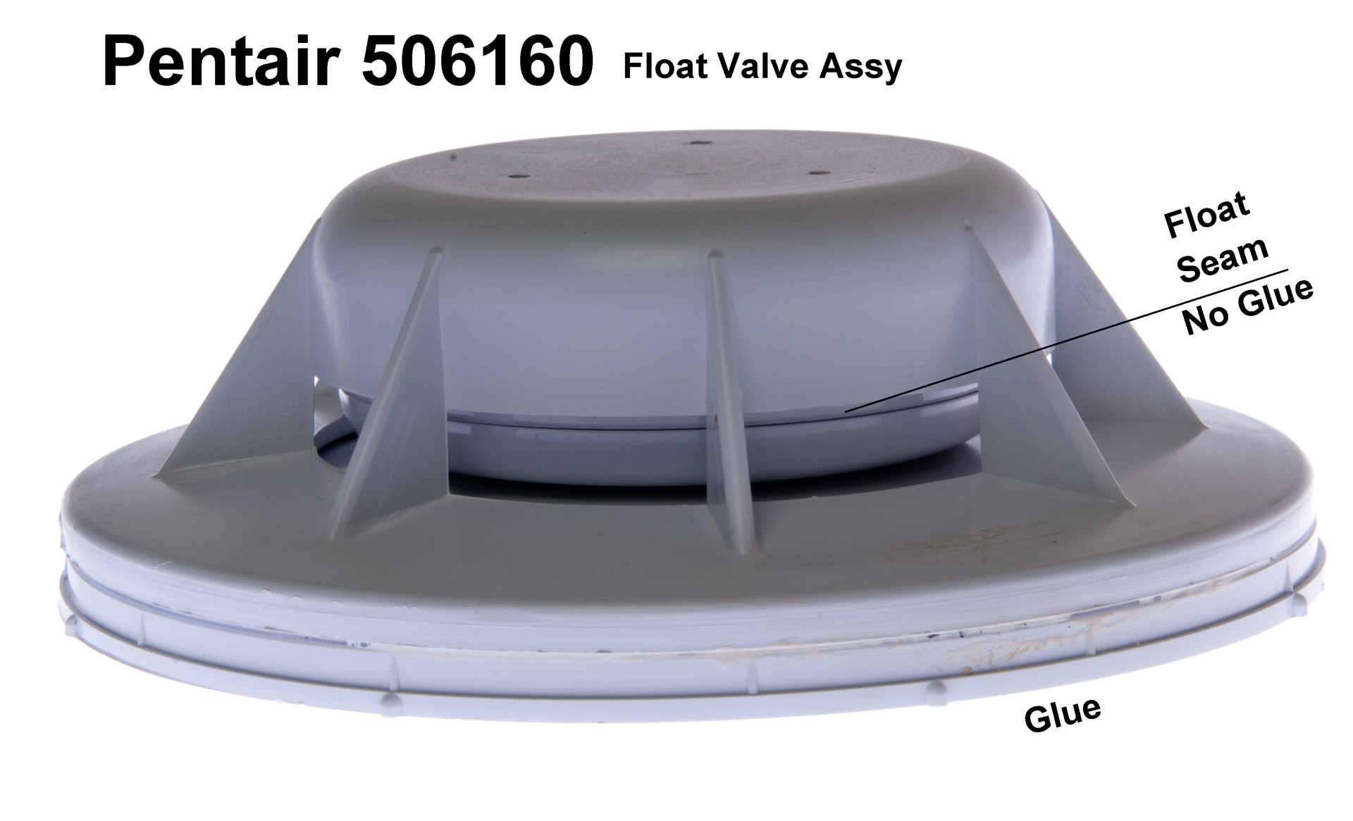


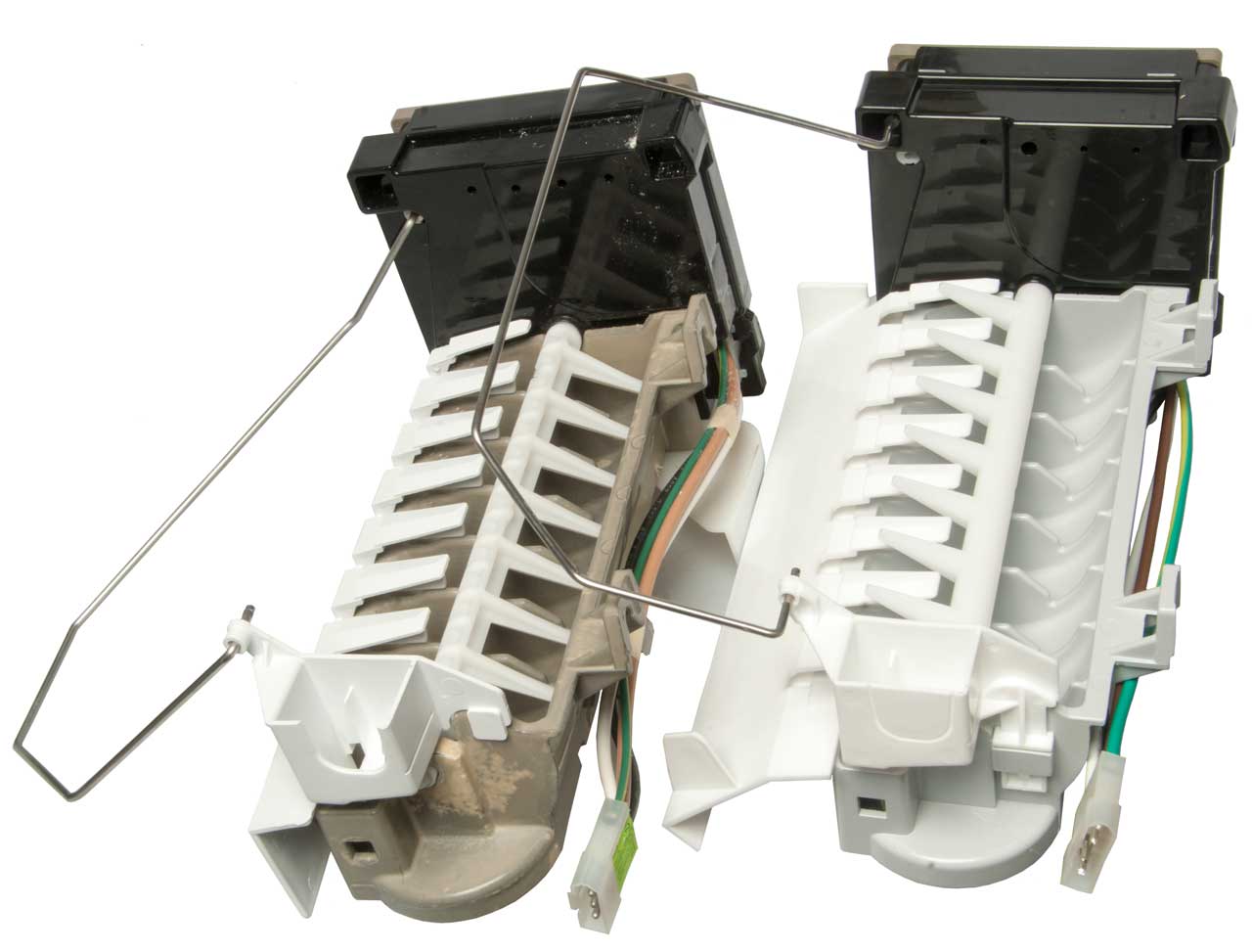

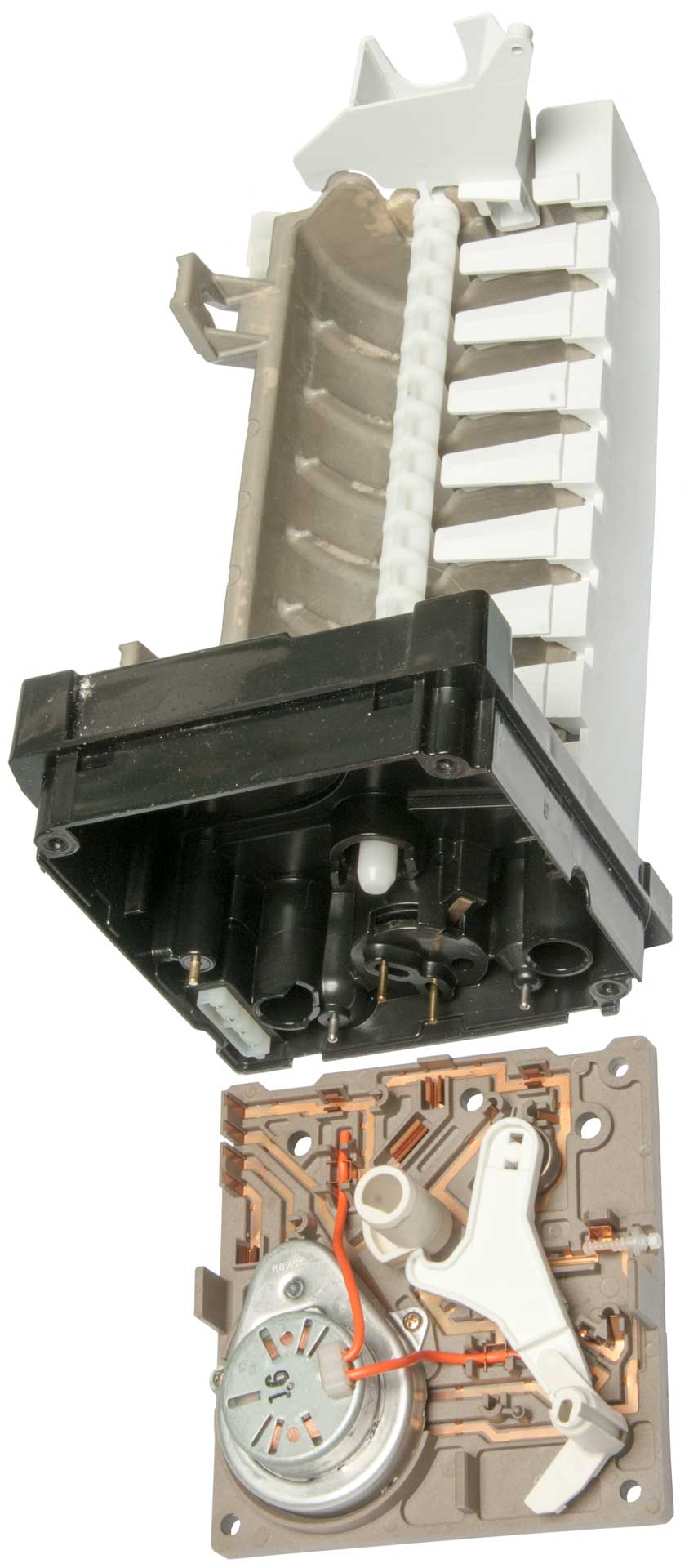
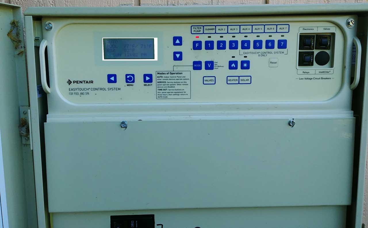
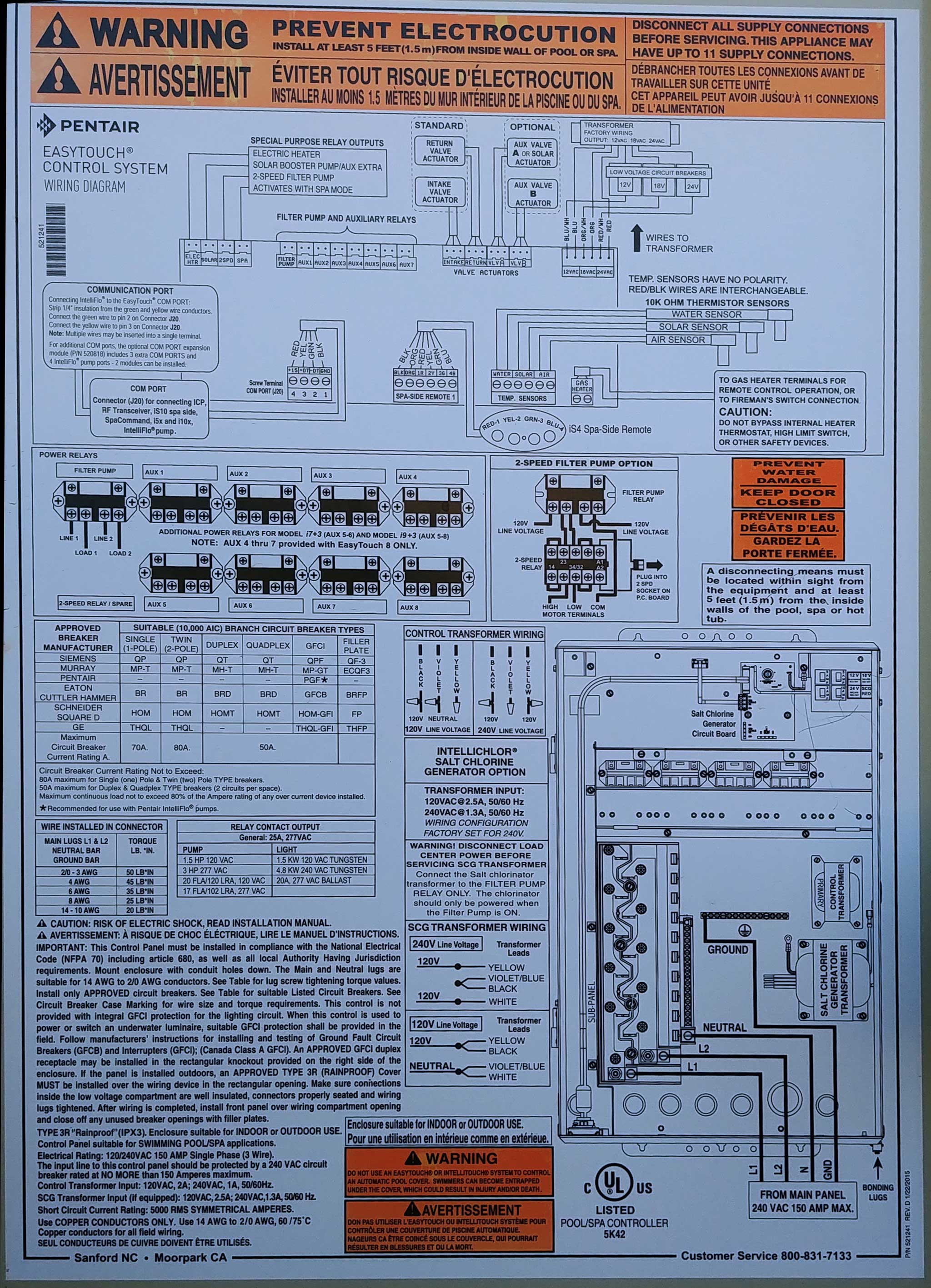

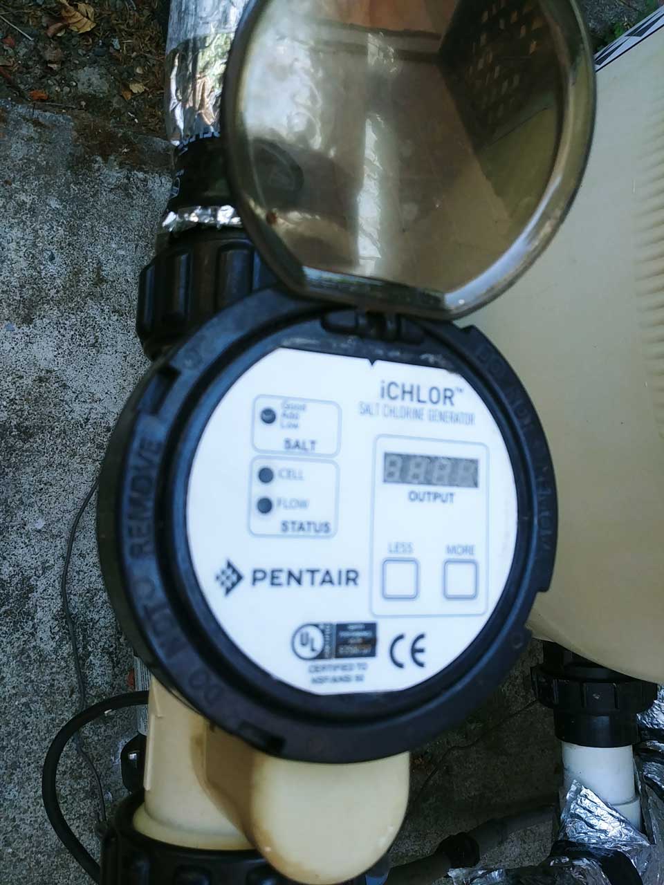
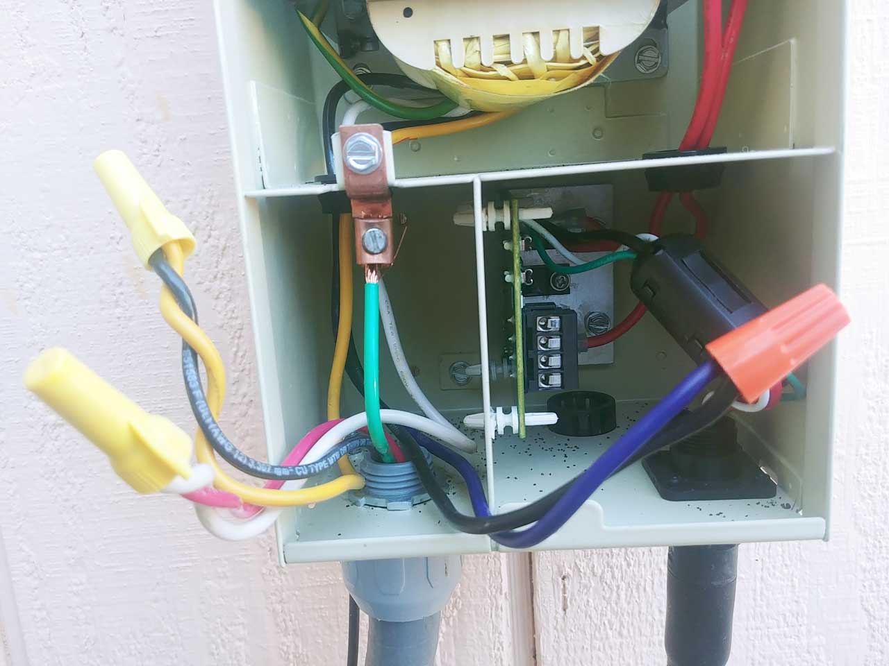


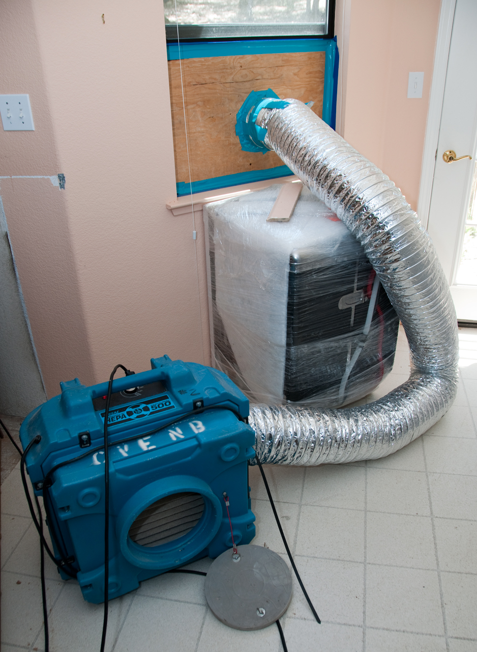


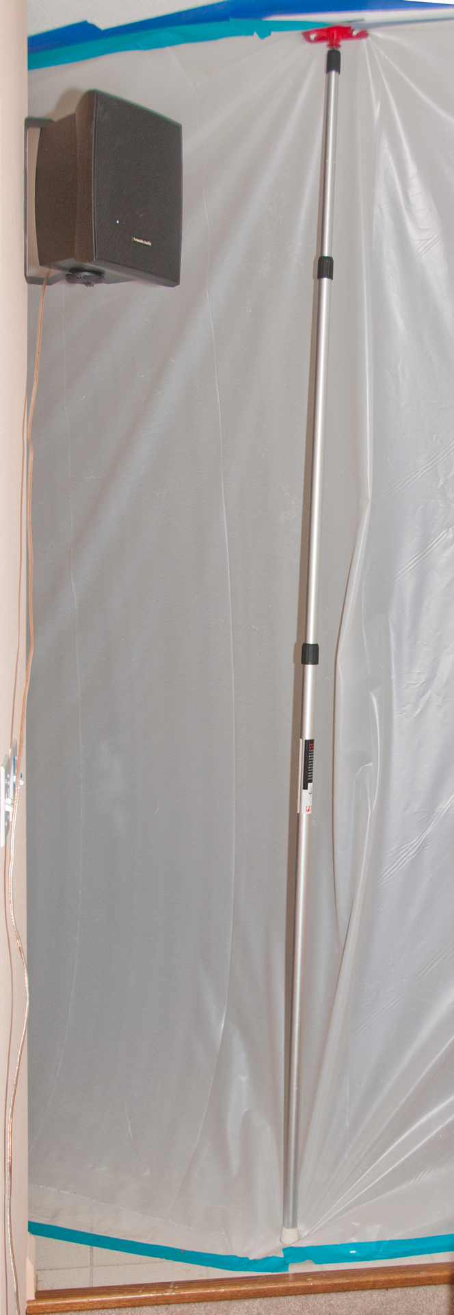


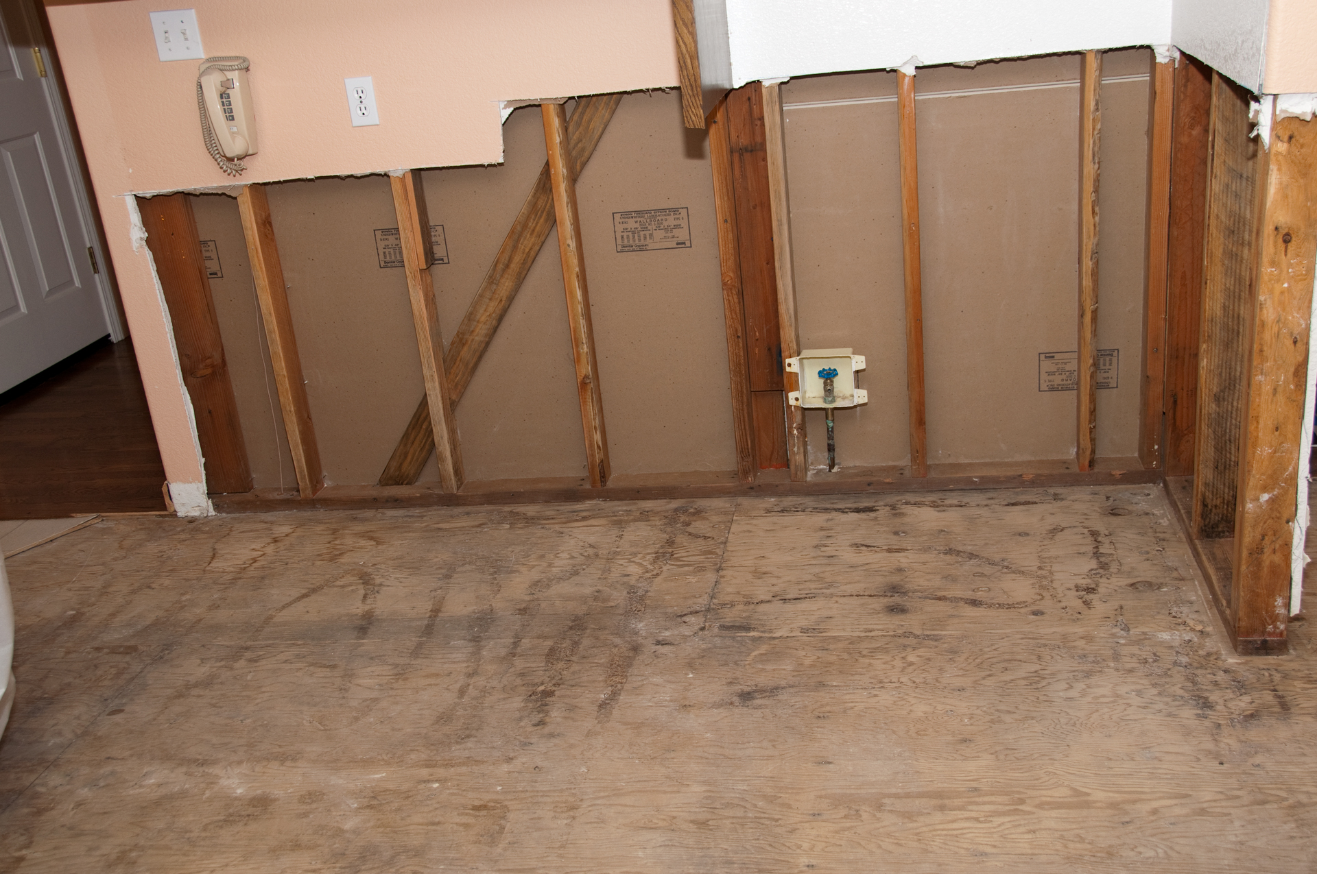

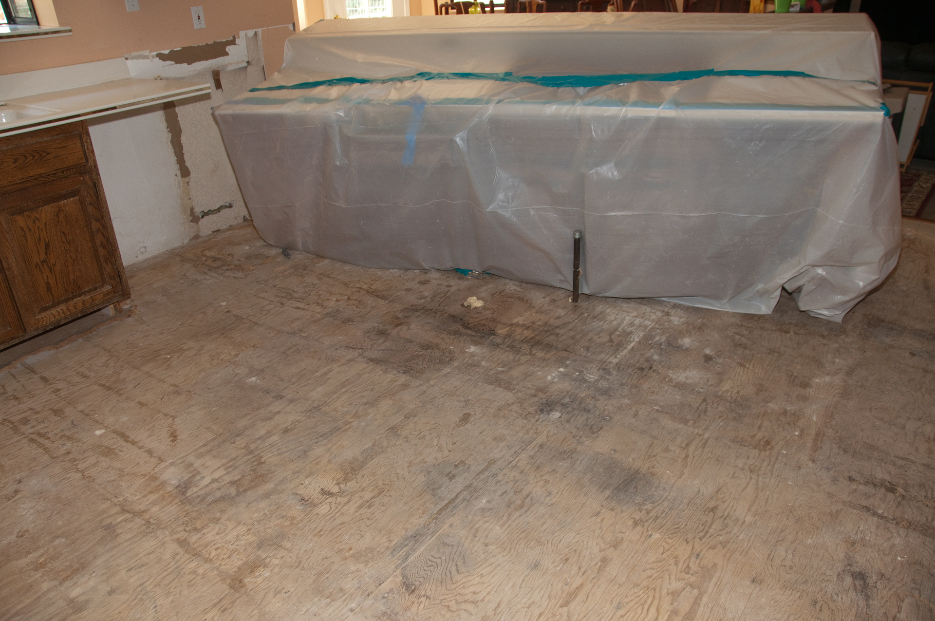

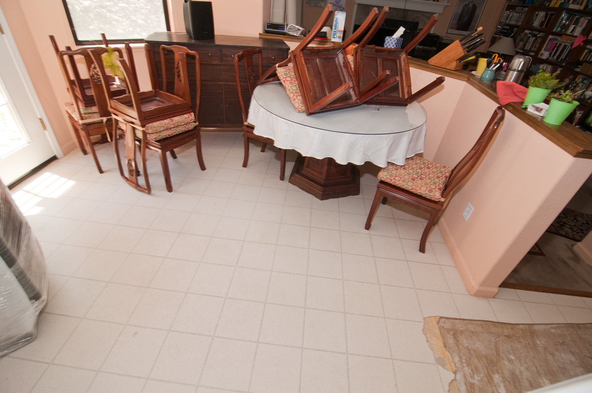
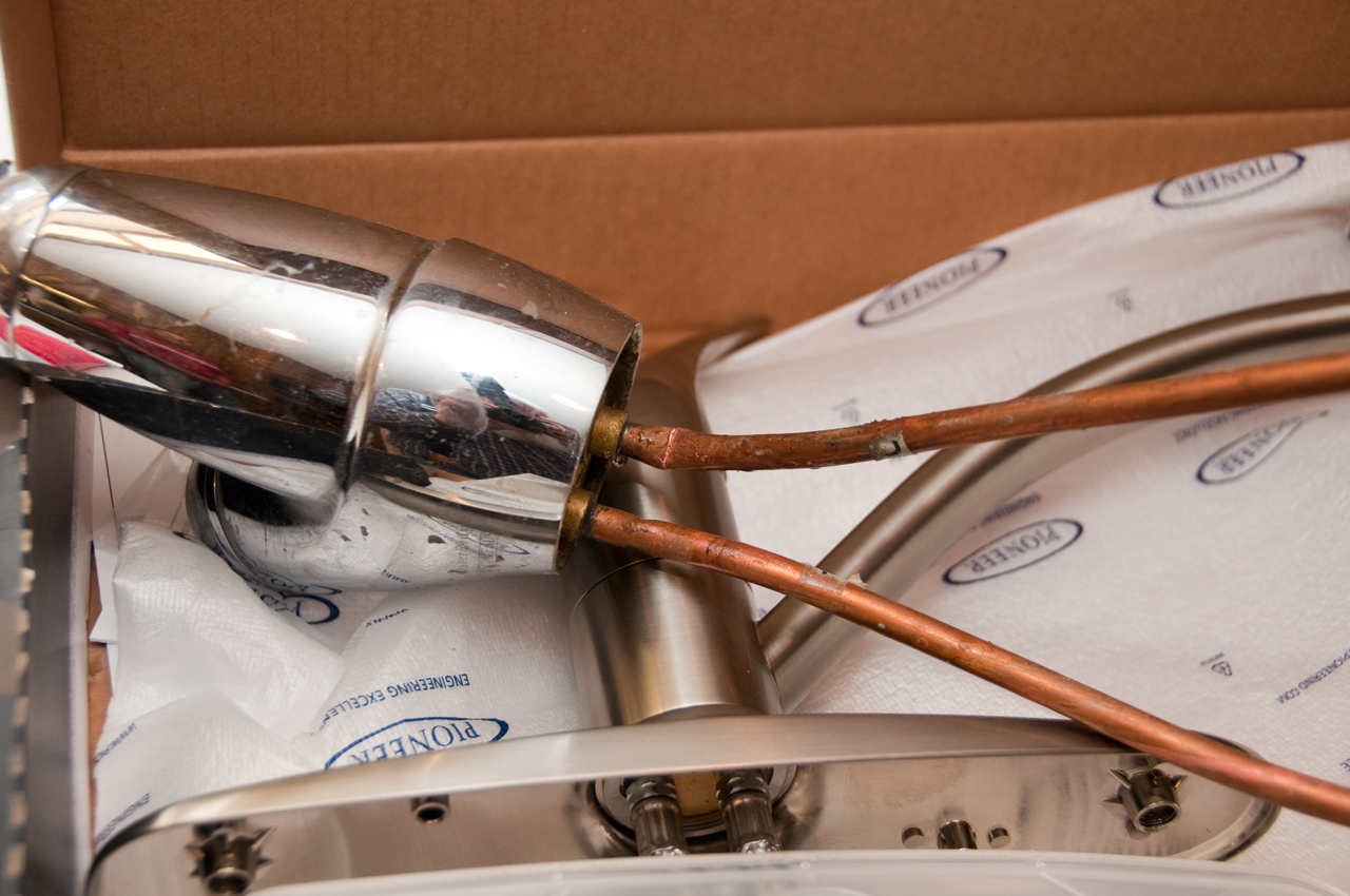


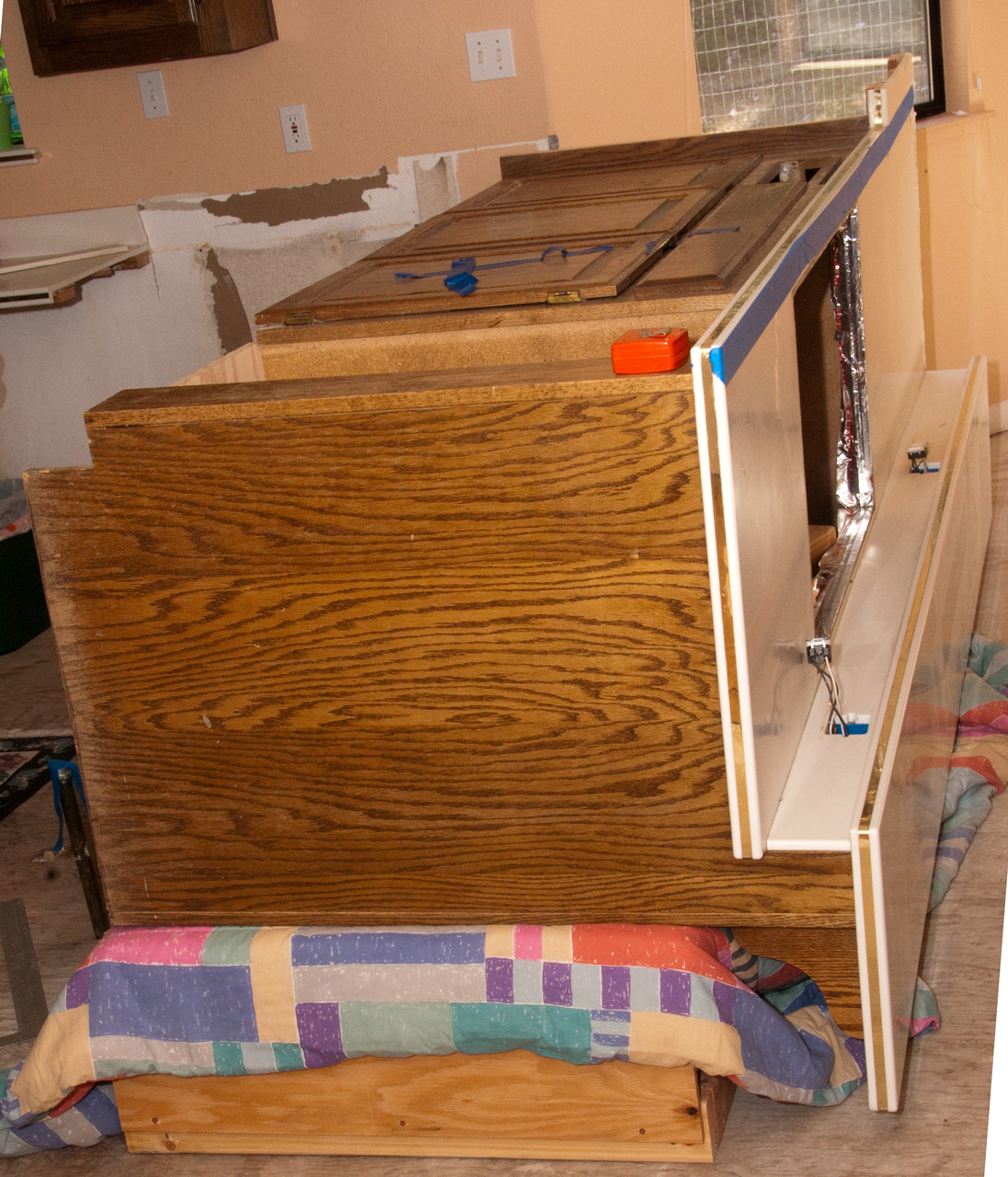


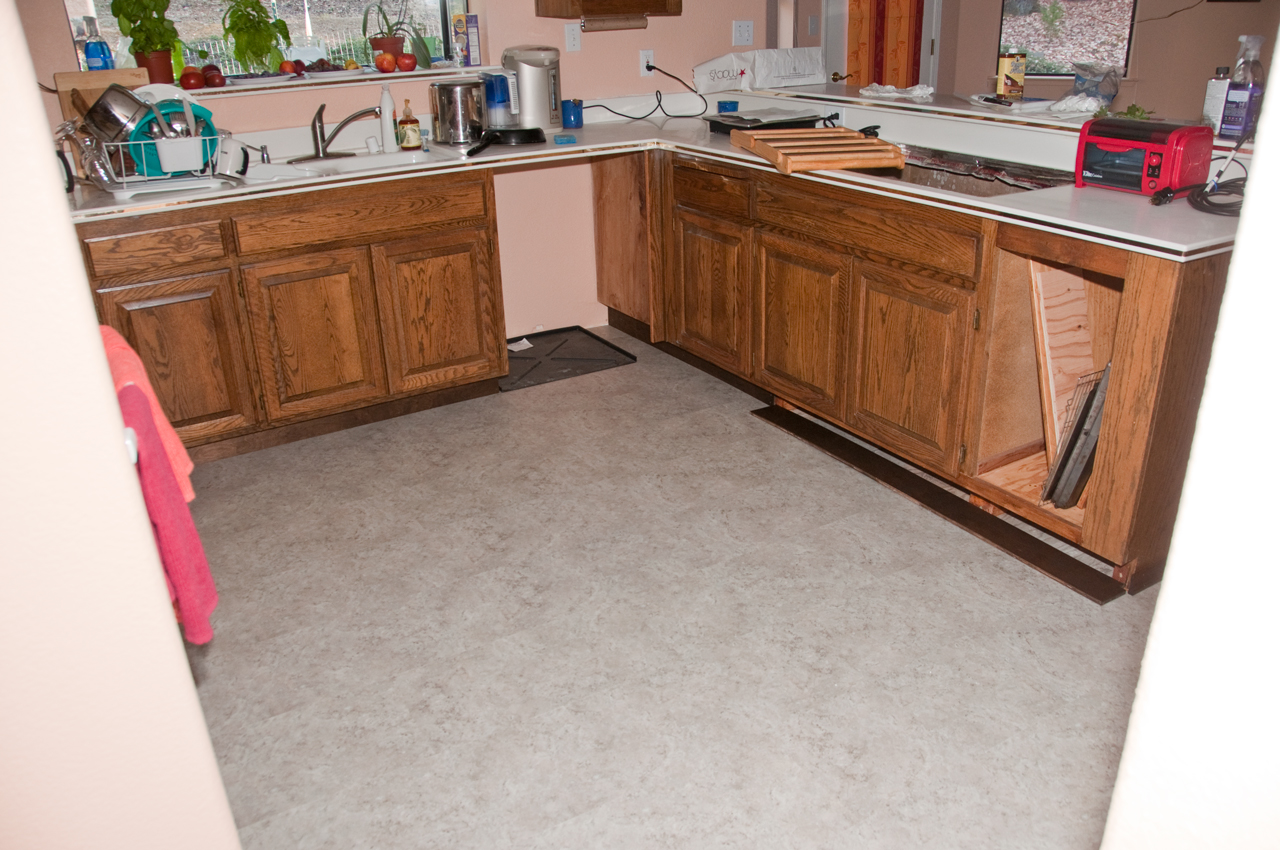
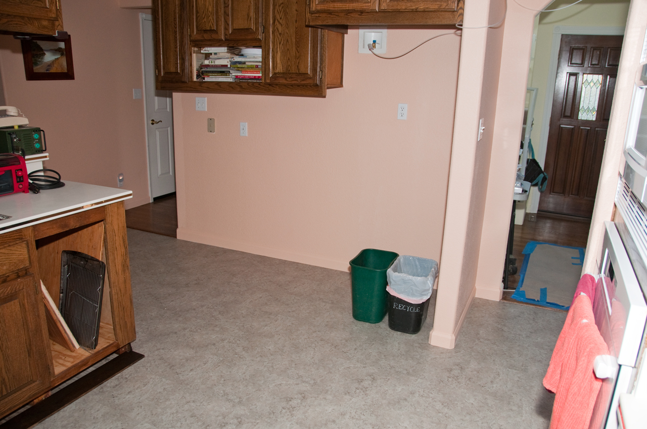

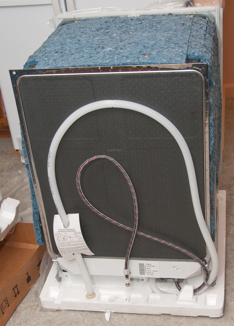

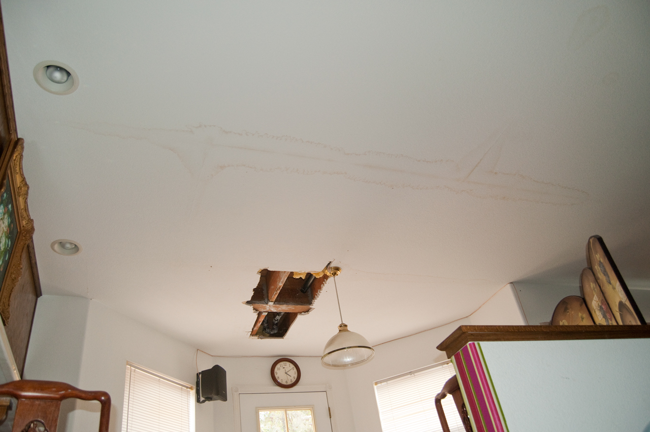


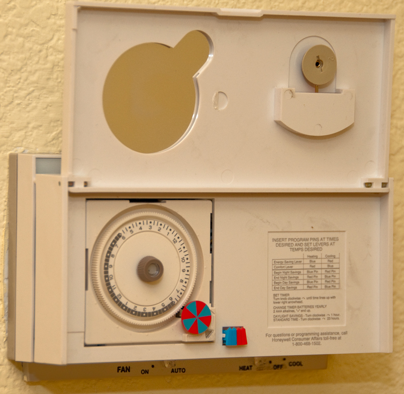


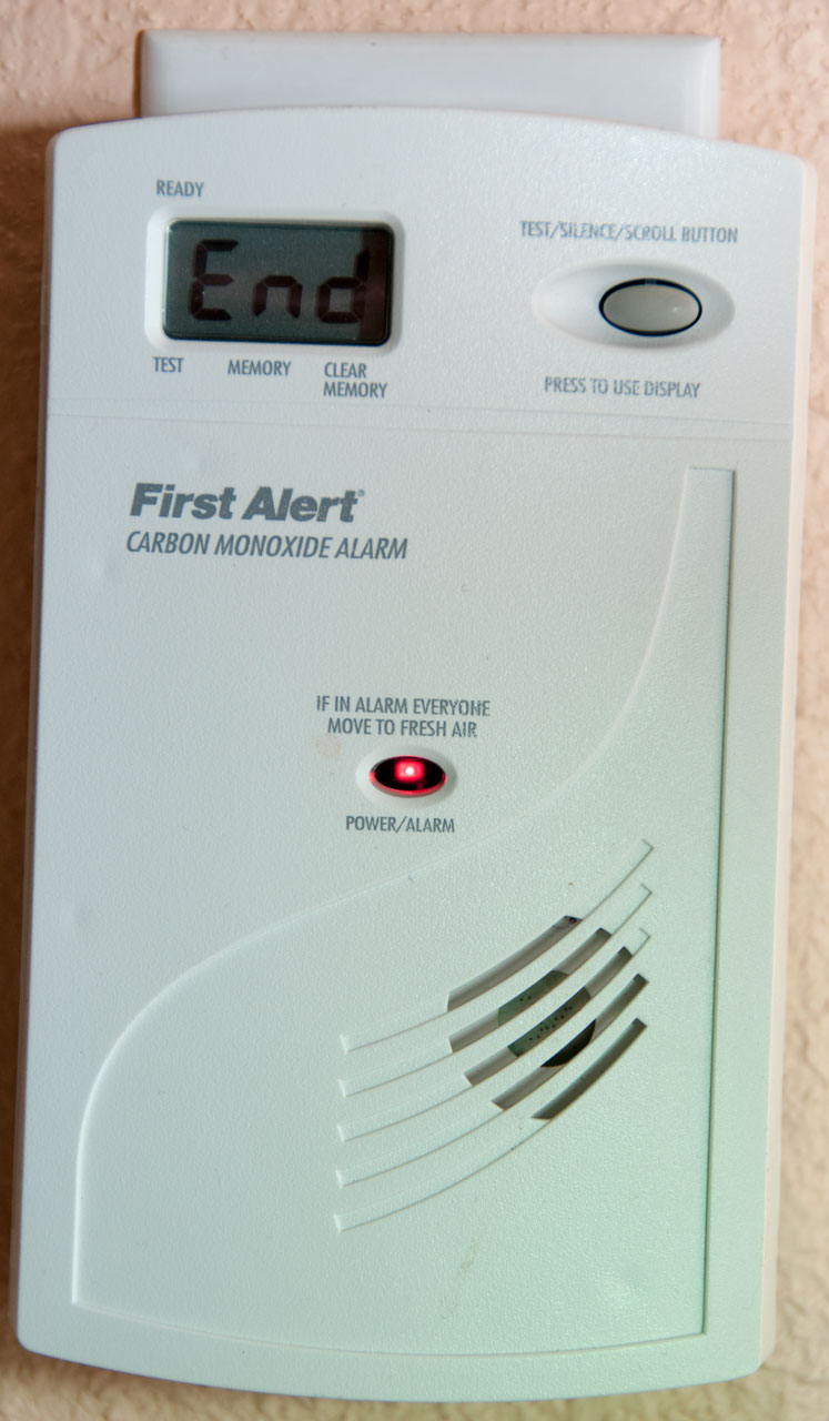
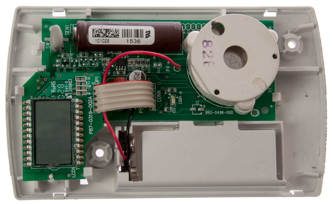
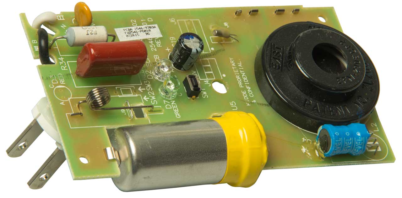

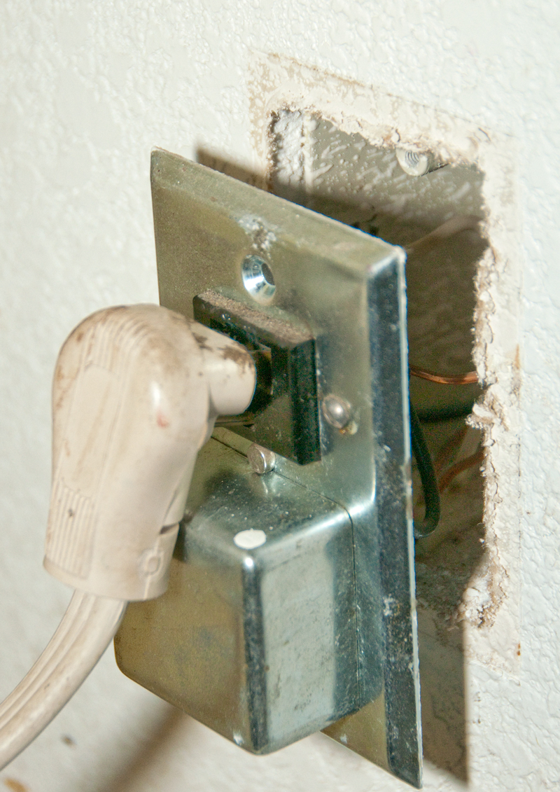
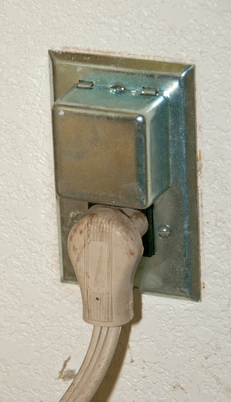


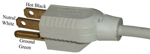
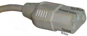
 This is called a