MX 4102 Transit Satellite Navigator
MX 4200D Differential GPS
© Brooke Clarke, N6GCE 2003 - 2026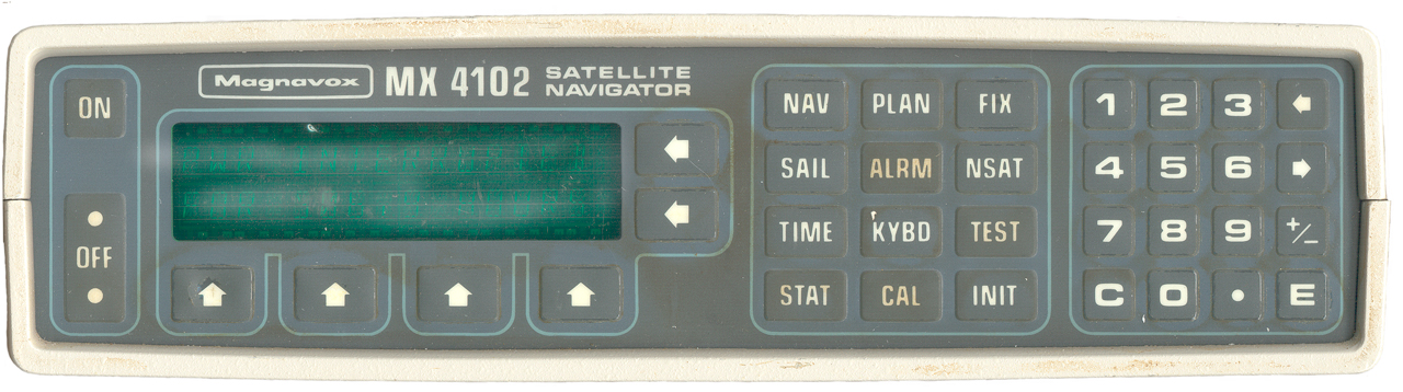
MX 4200D Differential GPS
MX 4102
Background
When Sputnik was put into orbit in 1957 some scientists at the Johns Hopkins Applied Physics Lab came up with the idea of using the Doppler shift measured on the ground to solve for the 3 dimensional position of the receiver. This required a satellite that transmits it's orbital elements. There are a number of papers on the JHAPL Legacy of Transit web page. The Navy Navigation Satellite System, as it was officially known, was designed mainly to allow the inertial navigation system on Polaris nuclear subs to be updated.
The very first Transit receiver took up about a dozen six foot high rack cabinets. The receiver for the Polaris sub was in two cabinets designed to fit through the hatch and so were narrower than a normal relay rack. The transistor had just come out and integrated circuits were non existent when the Transit satellite system went into operation. By the time Magnavox built the MX 4102 integrated circuits were common, hence it's small size and much lower price than the very expensive early Transit receivers.
The MX 4102 was designed by Magnavox, Torrence, CA (now Leica Geosystems Group) for use on pleasure boats and since there can be a number of hours between Transit fixes it includes dead reckoning to keep the position updated. This requires external compass and speed inputs from any number of the common types of sensors used abroad ships and the appropriate interface options for the MX 4102.
The MX 4102 uses a oven controlled oscillator (OCO) marked:
Electronic Research Company
Model EROS 800-MA-97
Mfg. p/n 626358-1 B
Freq 5.00 MHz
s/n 11703
Date 89-17
This is oscillator has a short term stability of 1E-10, equivalent to rack mounted lab type standard oscillators. A high stability oscillator is needed to measure the Doppler curve and to set the receiver tuning offset to account for the Doppler shift of the carrier on the low orbiting Transit satellites.
Other Models:
Model
System
MX1102
400 MHz Transit
MX1105
Omega
MX1107
150 & 400 MHz Transit
MX1112
400 MHz Transit + features
MX1157
150/400 Transit & Omega
Manuals
The Navigator's Manual and the Installation and Service Manual are dated June 1989.
Power
The unit operates from 10 to 30 Volt Dc power with positive going through the fuse. the current is just over 1 amp at a cold start and decreases to about 0.8 amps after the oscillator oven has warmed up.
Operation
By setting the approximate position, date and time by pressing INIT repeatedly the receiver can start searching for signals. When the signal strength at 400 Mhz gets above some threshold the receiver starts looking for the digital modulation. Now when there is no active satellite or I don't have a high enough antenna gain the receiver beeps and displays no fix (NFX). Apparently this receiver does not use the signal at 150 Mhz, only the 400 Mhz signal. This means that the corrections for ionosphere refraction are either approximated or not used.
The front panel has a Vacuum Fluorescent Display (VFD) with buttons below and to the right so the VFD can act as a menu system. In addition there are a couple of membrane keyboards, one with specific labels related to functions and the other with digits for numerical input.
Satellites
On 1 Jan. 1997 all the Transit satellites were turned over to the Navy Ionospheric Monitoring System (NIMS) and no longer use the Transit data modulation. Instead they now use a different modulation that's a classified NIMS format. These satellites are in a fairly high orbit and will stay there for a very long time, i.e. they will not decay and fall to Earth like a low orbiting satellite. But they are all now very old and so will cease to operate electrically when failures take them off the air.
The primary navigation frequencies are 149.985 and 399.970 and telemetry on 136.650 MHz.
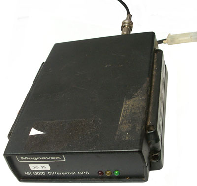
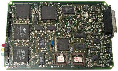
MX 4200D Differential GPS Receiver
The receiver puts out a little more than 5 VDC to the antenna so connected it to my house antenna and after some hours (was not paying attention) the Green LED was blinking. If the antenna is disconnected the green LED turns off and the Yellow LED comes on with no blink. Also, for no apparent reason, the green LED turns off and the Yellow LED comes on.
The Magnavox MX-50R DGPS beacon receiver could have it's output fed into the GPS receiver to mitigate the effects of SA.
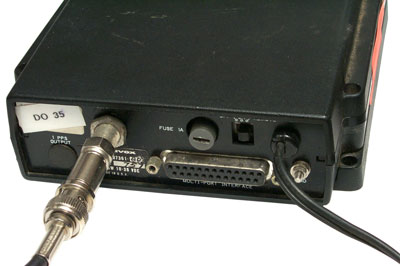
The rear panel uses a Type-F jack for the antenna connection and a DB-25F connector for the remote interface. There's a 1A Fuse and a switch marked Off On Remote.
A plugged hole is labeled 1 PPS Output and there's a ground post. On the side is a flourescent orange sticker saying Year 2000, In Process 2 Feb 99 - Maybe they found a problem?
The label on the rear panel:
Magnavox
Part No.: 707361-803 (the dash number is hand written), Serial No.: 751, Power: % Watts 10-36 VDC, Made in U.S.A.
The DB-25F connector is labeled "Multiport Interface" implying that there are two or more data I/O ports, i.e. Differential corrections are input and a position/Velocity/Time data stream is output and maybe a control input on the one or both of these.
After being powered up for a few days the green LED is mostly on, but blinks occasionally. There may be some type of code associated with the green LED.
If you have any information about these GPS receivers let me know.
 |
 |
 |
 |
Versions
MX 4200D - 6 channelMX 9212 DGPS -12 channel
MX4818 - ? channels
25 Pin D_Sub Connector
| Pin |
Description |
||
| 1 |
Remout
On (-) |
||
| 2 |
Port
2 Out (+) |
RS-422 |
Raw
Data |
| 3 |
Port
2 Out (+) |
RS-422 | Raw
Data |
| 4 |
Port
4 In (+) |
RS-422 | NMEA-0183 |
| 5 |
Port
4 Out (+) |
RS-422 | NMEA-0183 |
| 6 |
Port
3 In |
RS-232 | DGPS |
| 7 |
Port
3 Gnd |
||
| 8 |
Port
3 Out |
RS-232 | DGPS |
| 9 |
|||
| 10 |
Port
1 In |
RS-232 |
Ctrl
Msg |
| 11 |
Port
1 Out |
RS-232 | Ctrl Msg |
| 12 |
Ext
Pwr Rtn |
||
| 13 |
Ext
Pwr 12 V (+) |
||
| 14 |
Port
2 In (-) |
RS-422 | n.a. |
| 15 |
Port
2 Out (-) |
RS-422 | n.a. |
| 16 |
Port
4 In (-) |
RS-422 | NMEA-0183 |
| 17 |
Port
4 Out (-) |
RS-422 | NMEA-0183 |
| 18 |
|||
| 19 |
|||
| 20 |
Event
In |
||
| 21 |
Event
Rtn |
||
| 22 |
|||
| 23 |
|||
| 24 |
Port
1 Gnd |
||
| 25 |
Remote
On (+) |
Panel Lights
Red - Power OnYellow - Passed Self Test - Starting to operate
Green Flashing - receiving one or more stations
Green steady - navigating
Normal operation involves cycling between yellow, green flashing and green steady
Transit Patents
2470787 System for determining the position or path of an object in space, Paul W Nosker, App: 1944-05-04, Secret, Pub: 1949-05-24, - for locating aircraft, cited by 54 patents, many of which have application dates prior to Sputnik.
3063048 Discovery and location system, Frank W Lehan, Glenn L Brown, Space-General Corp, 1962-11-06, -
3133352 Satellite alert, Robert E Jasperson, 1964-05-19, - visibility prediction calculator for low orbit satellites, see: Flight Computer
3141167 Navigation system, Peter C Sandretto, ITT, App: 1959-12-07, Pub: 1964-07-14, - The idea of a satellite and using Doppler in the receiver, not Transit details.
3172108 Method of navigation, Frank T Mcclure, Navy, 1965-03-02, - 150 MHz, 96 min satellite orbit,
3191176 Method of navigation, William H Guier, Navy, 1965-06-22, - 2 minute data frame, 400 & 150 MHz,
3209357 Hyperbolic position determination, Wyatt Theodore, 1965-09-28, -
3233362 Toy satellite with radio signal generating means, Ralph R Chapman, App: 1961-12-19, Pub: 1966-02-08, - one transistor AM Tx.
3369236 Navigational receiver, Edwin E Westerfield, Jerry R Norton, Lauren J Rueger, Malcolm B Greenlee, Navy, 1968-02-13, - improvement over star trackers that only work in good weather (see: MD1). Includes getting accurate time signal from satellite. one aspect of a TRANSIT receiver
3534378 Wide band antenna for satellite navigation and related problems, Valor C Smith Jr, Chu Associates, 1970-10-13, - 150 & 400 MHz with pattern matches to satellites in the sky
4232389 Receiver for satellite navigational positioning system, Roger D. Loiler, JMR Instruments, 1980-11-04, - "...derives the actual satellite clock directly from one of the radio frequency carriers, rather than deriving the synthesized clock from the demodulation products of the carrier, and its recovery process is not dependent upon a local clock. Through the technique of the present invention, the effects of long term drift of the local receiver oscillator, and detector signal to-noise ratio errors, and other sources of error in the extraction of the two-minute time interval information from the received satellite signals are eliminated. Any drift in the oscillator of the satellite is recorded by the United States Naval Observatory, and is contained in the transmitted satellite signals. This enables the receiver to make appropriate corrections for drifts in the satellite clocks." patent includes many details of Transit signal.
Links
MX Marine, Leica Geosystems Group - offers GPS, DGPS equipment for ships
Hearsat - an orginazation with a mailing list for those listening to satellite signals, NIMS
Center for Ionospheric Research U of Texas- Transit Satellites -
HAARP - Slant-path Total Electron Content and Scintillation based on Transit Satellites using Northwest Research Associates, ITS10 Transit receivers.
Transit 5B-5 der wahrscheinlich älteste aktive Satellit - BableFish Translation - even without translation you can read the frequencies and see the images.
YouTube: Magnavox MX 1112 Satellite Navigator 1980 SatNav 400MHz, 40:45 -