JRC NRD-545 Receiver
© Brooke Clarke, N6GCE
1999 - 2023
Background
Setup
Modulation Modes
Computer Cable
JRC NRD 545 Controlling Software
NRDWIN Spectrum Plots
LabVIEW
Modification
Links
545
Decoders & Computer control
Multicoupler (Rx)
Antenna Coupler (Tx)
Other Receivers
Tranceivers
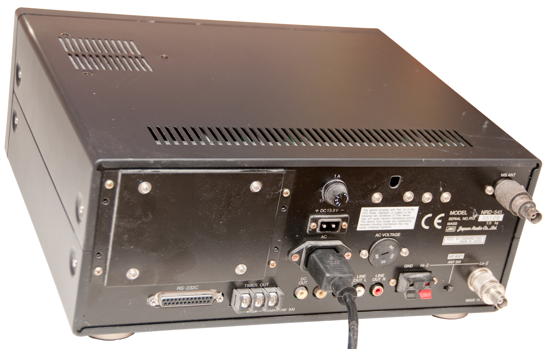
Background
This page is devoted to data from the Japan Radio Corporation model NRD-545
receiver. At first the JRC remote control program called
NRDWIN is being used to gather data. Then I
will be writing a LabVIEW program to do more interesting things.
100 kHz to just under 2 GHz coverage.
There is a report in the Passport to World Band Radio that says
that the DSP chip in the 545 has digital noise crosstalk that
causes the ultimate rejection to be tens of dB lower that it
should be. This may be the case, but the reason that I got
this receiver is that it has the narrowest IF filter bandwidth
available at 10 Hz. This allows listening for the carrier of
an AM station or the carrier of a TV station. It also allows
decoding WWV's 100Hz digital data by reading the s-meter with a
computer.
Review in German -
Setup
Cable
Spectrum Plots
Low Frequencies
AM Broadcast Band
FM Broadcast Band
Wide Band Scans
44 Meter Aero & Fixed
34 Meter Maritime Coastal
22 Meter SW BCB
19 Meter SW BCB
LabVIEW
Links
The Setup
McKay - Dymec DA-100 (now called a Stoner- )
active antenna located very near my GPS base antenna so the
location of the antenna is:
Latitude: 39:11:24.692
N Longitude: 123:09:50.548
W Altitude: 249.7 meters
819' 3" (WGS-84)
This is the antenna used up to 30 MHz. Above 30 MHz I now am
using a Radio Shack Scanner antenna (20-176) until I can put up
better antennas. This antenna is connected using about 50
feet of 75 Ohm coax and no amplifier.
The computer is an HP 8380 Pavilion with the HP M70 Monitor both
of which are very RF quiet.
Also the B&W 1.8-30 terminated Folded Dipole is used with
much better results.
Modulation Modes
CW
This is one of the earliest modes and consists of turning the
Continuous Wave carrier on and off using Morse Code. The
bandwidth needed is the narrowest of the commonly used modes and
most receivers have a 500 Hz wide IF filter for CW that also works
for narrow shift RTTY.
A disadvantage of CW is that when the key is up no power is being
transmitted. FSK has an advantage in that power is always
being transmitted so it's easier to define the two conditions
(zero or one).
Coherent CW
The idea was to make the on/off and off/on transitions at times
known to the receiver allowing better demodulation that when they
occur at random times. But it did not have any control of
the phase of the transmitted signal, which would improve the s/n
even more. Far better in terms of s/n are the Pseudo-random
codes and spread spectrum for getting the most signal for the
power used, although at the expense of modulation low bandwidth.
AM
Amplitude Modulation is used by medium wave and short wave
broadcast stations as well as aircraft. It changes the
carrier amplitude with the loudness of the modulation
signal. This is probably the oldest method of broadcasting
voice and when viewed on a spectrum analyzer there is a lower
sideband with voice modulation, a fixed carrier and a upper
sideband with voice modulation. It can be detected by a
simple crystal radio or by using the LSB or USB mode on a modern
receiver. Doing that has an advantage if there's
interference on either the upper or lower sideband. It's an
easy listening mode in that when the speaker's voice stops and
there's silence the radio goes silent. This is because the
carrier remains when there is no voice or music to modulate the
sidebands.
AM has another advantage in that if there are two stations on the
same frequency and they are at the same power level a receiver
will hear both stations. This is not the case with FM
modulation where the stronger station completely suppresses the
lower power station. That's an unacceptable safety
consideration for aircraft.
FM
In Frequency Modulation the frequency of the carrier is changed
with the loudness of the modulation signal. Since the
carrier is always on at full power the audio output will be quiet
when there is no modulation signal. This is the mode used on
the VHF broadcast band. The modulated signal has a bandwidth
that on the order of 100 kHz, much wider than the bandwidth of a
music modulation hence there is some process gain that works in a
similar way to antenna gain.
Narrow band FM that's used for utility communications has a signal
that's 5 kHz wide and a voice signal is about 3 kHz wide so it
doesn't have much process gain, but you can get a lot of channels
into a given slice of the spectrum. In this application the
FM capture effect that pervents hearing two stations at the same
time is a benefit because the other station is most likley one you
don't want to hear.
SSB
In Single Side Band modulation either the lower sideband or the
upper sideband that's in an AM transmission is sent to the antenna
and the carrier is supressed completly. This makes SSB verry
efficient in terms of getting the highest radiated signal for the
power used. But it requires much higher frequency stability
in the transmitter and the receiver.
If you were listening to a SSB radio and music went soft the noise
level would come up, not at all an entertainment type of mode.
FSK
Frequency Shift Keying is a way of sending digital data. The
transmitter is at one frequency for Mark and another frequency for
Space. It's much easier to make the binary decision with FSK
than with CW where one of the conditions is the transmitter is
turned off. This mode was used to send Radio Teletype
messages.
MSK
Minimum Shift Keying is a version of FSK where the shift is as
narrow as possible. It's used on LF, VLF and ELF stations to
keep the transmitter frequency within the bandwidth of the high-Q
antenna matching network.
PSK
Phase Shift Keying is similar to FSK except it's the phase of the
transmitter that's being modulated.
Spread Spectrum
By making the transmitter signal much wider than the modulation
signal bandwidth there is a process gain that has the same effect
as using more RF power or an antenna with gain. This is used
in satellite TV systems where the RF bandwidth is on the order of
36 MHz compared to a signal bandwidth of 5 MHz. In the GPS
system the signal level at the Earth's surface is below the ktb
noise level, it's only after demodulation of the pseudo-random
code that the s/n comes up. Note that since all the GPS
satellites transmit on the same frequency they differ in what
pseudo-random code each satellite uses so the codes are chosen to
have very low cross correlation. This also means that the
s/n radio will never be very high because there's always going to
be interfering signals from other satellites.
Modern Digital Modes
Early telephone computer modems used simple FSK and could only
achieve limited data speeds on the plain old telephone system
(POTS). The next generation modems used a modulation that
sounded like noise and could support much higher baud rates.
The latest Digital Subscriber Line (DSL) modulation uses
frequencies above hearing (allowing the POTS telephone to still
work on the same line) and is adaptive in that it changes what
frequencies are used depending on line condition. It's not
uncommon when there's trouble on the line for the POTS phone to
quit working while the DSL signal still gets through (although at
a slower speed).
Modulation Test Equipment
Oscillioscope
Displays the amplitudeof a signal vs time. For example:
Rigol DS1052E The scope is
the oldest of the three dynamic display instruments. It was
used to observe AM modulated RF signals. If the modulation
was too strong it would cause the RT to clip on the negative peaks
causing a lot of distortion.
Spectrum Analyzer
Displays the amplitude of a signal vs frequency. For example
the
HP 4395A. This is a much
more complex instrument in that it consists of a receiver that has
a sweeping local oscillator and various band pass filters.
Modulation Domain Analyzer
Displays frequency vs time. If you think of the signal
inside a cube where the three axis are Amplitude, Time and
Frequency you can get three views of the signal depending on which
face you look at. It takes modern digital signal processing
techniques to make a modulation domain analyzer so it's a fairly
new type of instrument.
Specalized Analyzers
There are phase-amplitude and I-Q displays that are specific to
certain modulation schemes.
Cable
The RS-232 cable that is sold by Universal radio to go
with this receiver has DB-25(m) connectors on both ends and is a
null modem cable:
1 - 1
2 - 3
3 - 2
4 - 5
5 - 4
6 - 20
7 - 7
17 - 24
20 - 6
24 - 17
It turns out that my computer only has DB-9(m) com ports (which
have a reversed pin numbers from the 25 pin cables) so I made up
my own cable (545toPC.pdf drawing):
|
NRD-545
|
Cable
|
Computer
|
|
DB-25(m)
|
|
DB-9(f)
|
|
2 Tx
|
Red
|
2 Rx
|
|
3 Rx
|
Green
|
3 Tx
|
|
4 RTS
|
White
|
7 RTS
|
|
5 CTS
|
Black
|
8 CTS
|
|
7 Gnd
|
Shield
|
5 Gnd
|
| |
|
1, 4, 9*
|
* on the computer connector pins 1, 4 and 9 are tied
toghther. This fools the computer into seeing hardware flow
control, it may or may not be needed here, but I do this to be
safe.
JRC NRD 545
Controlling Software N545PRO.EXE
The English version is new as of March 2003.
Date: Sun, 16 Mar 2003 11:58:32 +0100
   From: Martin-Fischer-von-Frieling@t-online.de
Subject: Re: N545Pro Software now Freeware

Registration is easy. Enter the program, click

Help
then
Registration...
enter

NRD545EN   as ID

2B353B84344E508A  as Password

Thats all

Cheers n´ beers, Martin
http://www.thiecom.de/mlb.htm Receiving longwire matching
transformer for 100 kHz to 40 Mhz German page but "RF Systems" in
title.
NRDWIN Spectrum Plots
There is a spectrum plotting function in the NRDWIN
software. The radio is set up for mode, IF bandwidth, etc.
then the "Setup" function in the PanoranaRecv program is set for
Start, Stop and Step, and single/continous sweep, when OK is
clicked, the scan starts. When the plot appears, if the
cursor is clicked once a marker is seen and with a double click
the radio is tuned to the marker frequency. It is hard to
get the cursor exactly on the peak so I typically need to go back
to the receiver and tune up or down a little. The plot does
NOT show the mode and IF BW, adding these would be a good thing.
Radio Locator -
Extensive data including station web pages
AM FM Station -
Low Frequencies
When listening to NDBs (Non Directional Beacons) with a
narrow IF BW the LSB carrier and USB can be separately tuned.
10 kHz -
100 kHz, CW-narrow
100 kHz - 200 kHz, CW-narrow
200 kHz - 300 kHz, CW-narrow
300 kHz - 500 kHz, CW-narrow
AM Broadcast Band
One thing that became clear is that this receiver is
picking up more than one station on many frequencies!
Sometimes it is possible to separate them using either LSB, USB or
ECSS (pressing this button causes LSB then USB then OFF,
sequentially). Note that plain old LSB and USB depend on the
accuracy of the station carrier relative to the NRD-545 (I have
the high stability option) and may work better than ECSS in this
case of 2 stations. A long term solution is a stearable
antenna system. I will be working on that in the future.
500 kHz - 1800 kHz, step 0.25 kHz,
CW-narrow mode, all the following AM BCB plots were done with
0.25 kHz steps
500 kHz - 700 kHz,
CW-narrow
mode
700 kHz - 900 kHz,
AM-narrow
mode
900 kHz - 1100 kHz,
AM-narrow mode
1100 kHz - 1300 kHz, AM-narrow
mode
1300 kHz - 1500 kHz, AM-narrow
mode - my local AM station is easy to see
1500 kHz - 1700 kHz, AM-narrow
mode - a number of stations are in the new 1600 to 1700 band
The 545 will receive stero AM and FM when headphones or an
external amplifier are used.
www.AMStereoRadio.com
- has station listings
FM Broadcast Band
88 MHz - 108 MHz, FMW mode
- There is a HUGE birdie at 106 MHz! The manual mentions
that there will be some.
Wide Band Scans
Birdie Search - 30 -
1230 MHz - there appears to be a limit of 1,000 MHz in the NRDWIN
panaromama software.
5.0 - 10.0 MHz, AMw 23:00 UTC
10.0 - 15.0 MHz AMw
15.0 - 20.0 MHz AMw
108.0 - 136.0 AMw
44 Meter Aero & Fixed
6,525 kHz - 7,000 kHz
CWn
34 Meter Maritime Coastal
8,195 - 8,815 kHz CWn
22 Meter SW BCB
13,600 - 13,700 kHz CWn
13,700 - 13,800 kHz CWn
13,800 - 13,900 kHz CWn
19 Meter SW BCB
15,100 - 15,200 kHz CWn
15,200 - 15,300 kHz CWn
15,300 - 15,400 kHz CWn
15,400 - 15,500 kHz CWn
15,500 - 15,600 kHz CWn
LabVIEW
I have started to write some LabVIEW code for the NRD-545.
Since the IF bandwidth can be made very narrow and in addition there
is a notch filter that will take out a continuous tone it is
possible to "hear" the 100 Hz digital sub carrier on the WWV HF time
signal stations. I have the start of a program that outputs
the digital time code.
Modification
There's a rumor that if you put a zero Ohm resistor
(short) in the R13 position inside the converter it will unblock
the receiver, but I have not yet confirmed this.
Links
545
Japan Radio Corporation
- NRD-545 - DSP - CHE-199 converter - Remote Control - Abridged
Operation Manual - Nrdwin software is downloadable
Universal Radio - NRD-545
-
Lowe Electronics Ltd - Review -
compared to WJ HF-1000
Dave's
Radio Receiver page - NRD-545 -
Premium-RX Home Page
- Table
Premium Rcvrs - High End
Commercial -
Battle of
the Shortwave Super Sets! The NRD-545 DSP Receiver Versus the
535-D by David Sharp -
JRC mailing list - @ www.QTH.net
NRD-545
Comments/News - review by davez
JRC
NRD545
with
VHF/UHF
Converter by Bob Grove
LEM132 - DXpedition to Lemmenjoki - used 545's
Orchid City Software
- DX & SWL - Freeware control software
FCC ID = CKENRD-545 - wideband converter block diagram, internal
photos (huge file B&W), test report, there appears to be a
CR2032 battery on the Display Board see manual pg 32, on line Manual
-
Everything
You Ever Wanted To Know About the JRC NRD 545 (But Were Afraid To
Ask) - plots of AF response
SWL
IR Remote
- SWL IR
Remote for JRC NRD-535 and NRD-545 Aug 2004 to be available
Sep 2004 - Use a standard TV Universal IR remote to control the 545
radio.
Decoders & Computer control
Worldwide Utility News (WUN) - THE main source for utility
information
HF-FAX - THE main source for
visual radio modes fax, sstv, weather sats, etc.
shoc - dealer in high end radios,
antennas, decoders, etc
Wavecom - nice DSP base decoder
manf - the W40PC and W41PC-MkII are ISA cards, the other decoders
are stand alone boxes (2008 - the 40 & 41 manuals & docs
still on line)
Klingenfuss
Publications - utility data base & dealer for wavecom
decoders, also has CD-ROM with many digital sounds that can be fed
into the decoder
Computer International -
ARMAP, Radio Com, Visual Radio & Wavecom dealer
Bonito Communication
Technologies - Radio
Com - does DSP using the PC CPU
VisualRadio Automated Monitoring (Liedtke GmbH) -
RadioRaft - has
free demo version, needs interface circuit or modem - the "RR
modes user's guide" (at the bottom) there is a frequency list by
mode. sole proprietor
DXtreme - logging software
Icom CI-V Interface by Ekki, DF4OR
Hoka - the code 30 is an A/D card
for a PC (probably a modem with filters) plus DSP software running
in the PC, the code 3 is an dongle interface system like Radio Raft
Robert S. Parnass - Control
Software for the 545 and other radios
SkySweep
Technologies - Windows based decoders done in software, 3
price grades, many many HF and VHF type modes
Multicoupler (Rx)
SkyWaves by Al Klase -
N3FRQ - passive multicoupler and 4:1 ant balun plans
Stridsberg Engineering -
Multicouplers - I have the MCA104.
It's abut the size of handheld calculator and will run off of a 12V
battery. Rated for 100 kHz to 50 Mhz. Works GREAT! I
tried just using a "T" connector to connect two radios, but that
degraded the signal over 10 dB!. With the MCA104 (2 ports
termintated now) both receivers are hearing as well as if they had
the antenna all to themselves. By the way they also make rack
mount versions with a lot more outputs.
Boatanchor Dreams
- Collins
CU-168/FRR Antenna Multicoupler - Boatanchor Webring
-
Collins CU5069 32 port multicoupler
Westinghouse KMS-101, 2-32 MHz, 72 Ohm Input, 8 outputs phase and
amplitude matched. Input band pass filter. Vietnam era.
Antenna Coupler (Tx)
Note that an antenna coupler typically has a ceramic
insulator holding a connection for a wire that goes to the
antenna.
The coupler is placed very near the antenna.
An antenna tuner (aka line flattener) typically has coax inputs
and coax outputs and is used near the transmitter.
Harris - RF-2601 Antenna
Coupler -
SGC - FAQ -
Butternut remote antenna tuner - motor driven cap across the
80m coil, works on 80 & 40, little or no effect on higher bands.
Murphy Surplus has the C-3698/URA-38 control
box & CU-938/URA-38 ant. couplers
Other Receivers
R390 -
R390A/URR - WA4HHG Chuck Rippel Restoration, Service, Parts
R-1051B
- R-1051
-
SRR-13A
-
Yahoo Groups: armyradios
- NRD545 -
Ten-Tec - 340 w/o front
panel = 331
- RX-320
PC Radio - 340 review at Radio
Netherlands, 1254 Kit
Review -
Collins - HF-2050 - the first radio to use DSP
Collins - AN/VRC-100 -
URG-III -
Racal RA-6790GM - RA1792, RS2290, RA1784, RA1772 -
RA3791 - 1792@WJ
Ford
KNEISNER+DOERING -
KWZ-30 -[ KWZ50 as of
24 Apr 2008 not shown as available]
Harris -
RF-590 - $2,250@TS&S
- Preselector @Mike Murphy
Sunair Electronics -
tranceivers, amplifiers, CU-2430
antenna coupler, R9200
receiver
Palstar R30 - gets very good
reviews, in the same class as the Collins 2050!
WJ HF1000 discontinued, replaced by the WJ8711 now sold by BAE
Systems, note the WJ8711 includes IEEE-488 interface (not on
HF1000).
Toronto Surplus &
Scientific - Radios
Andrew Cygan PROFESSIONAL
RECEIVERS - HIGH QUALITY SHORTWAVE COMMUNICATIONS
Tranceivers
Motorola Mobile Radios -
MICOM-2E - ALE, 1.6 - 30 MHz, 125W - Mobile Workstation 520 computer
with seperate LCD, KB, CPU box
Ten-Tec - Pegasus - Ten-Tec has
announced a Front Panel (FP) version of the Pegasus that hopfully
will retain the computer control capability.
Harris - RF-350
-
ICOM - 706MKIIG
- this is a very capable rig in a small package. Brooke's 706 Page -
Elecraft -
Totally QRP by K4MSW
Back to: Brooke's PRC68 Products for Sale, Personal Home Page, Military
Electronics Information, Electronics
page
Page created 19 Jan. 2000.