SB-4151/GRC-206 Power Distribution Unit PDU
© Brooke Clarke 2008
 |

|
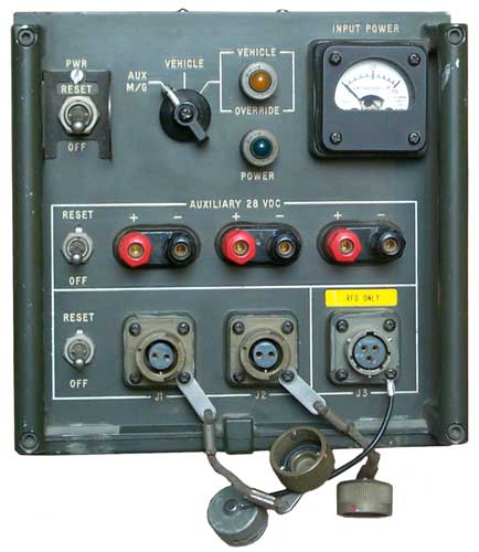
Front of PDU
|
Right Side Main System 28 VDC Inputs Vehicle & Aux
24-22 Insert with four each 4 ga pins (135 A rating)
|
Background
This is the box that controls the DC power to part of the GRC-206
system. The O-1814 Time and Frequency Standard and the C-11169 Signal Distribution Unit and maybe the Crypto boxes (KY-57, KY-65). The radios are powered by means of the standard military vehicle 4 contact power cables to their mounts.
The first four versions of the GRC-206(V) system used a DC generator
that was gas powered. But starting in year 2000 the military
switched to a deisel AC generator for fuel compatibility with the HMMWV. So the M455-1 AC to DC Power Supply was added to the system. It would be cabled to the J5 Aux power input.
Numbers
p/n: 812082-801
NSN:
6110-01-140-8419
contract: FO4606-81-C-0017
Controls, Connectors and Indicators
Front Panel
Master PWR:RESET -OFF switch
Power Source Switch
AUX:M/G or VEHICLE or VEHICLE OVERIDE (with associated indicator lamp)
Green POWER lamp
Input Voltage Meter 0 to 50 marked 25 at mid scale.
Auxiliary 29 VDC three pairs of 5-Way Binding posts with their own RESET - OFF switch
J1, J2 and J3 (RFO Only) circular connectors and their own RESET-OFF switch.
J3 powers the
O-1814 Radio Frequency Reference.
J1 or J2 powers the
C-11169 Signal Distrubution Unit J14.
It's not clear what the other jack (J1 or J2) powers, maybe the crypto boxes?
Rear Panel
J6 Main Power Input 3 socket connector for the Motor/Generator
insert marked A, B, C next to sockets and CANNON 20-19
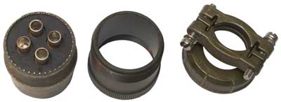
Right Side
MS3106R-24-22S Main DC Power Input connector without the coupling nut.
A major problem for me is how to heat up those giagantic solder
cups. No way my bench soldering iron can do it. And I
question using a flame.
Available from William Perry.
Both have power wiring:
Pin
|
|
A
|
+28 VDC
|
B
|
DC Return
|
C
|
Chassis Ground
|
D
|
(J4 only master switch)
|
J4 VEHICLE POWER is a 4 pin male connector that mates with the common vehicle power cables like the CX-13302 or CX-4720
NOTE
Pin D is the system On-Off switch and must be grounded in order to
power up the system.
This
wire was tied to the vehicle oil pressure light. When the engine
is running Vehicle Power is available, but when the engine is off the
Vehicle Override mode must be used. Since this runs down the
vehicle battery there's a warning light to warn the operator.
I've heard that the generator was not used, just the engine was kept
running which also provided heat for the operators.
|
J5 AUXILIARY POWER is a 4 pin male connector that mates with the common vehicle power cables like the CX-13302 or CX-4720
It's not clear how these inputs relate
to the Power Source Switch above. The VEHICLE switch position
clearly relates to J4.
Inside
 J6 on photo right is the main input and output connector. It's wired:
A2 Red
B 2 Green Chassis ground
C 2 Black
the two main input connectors are wired:
J4 VEHICLE
A 2 Red
B 2 Black
C 2 Green
D small white to SW1 mode
J5 AUX
A 2 Red
B 2 Black
C 2 Green
Contactor
Subassembly
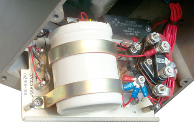 Unscrewing
the 4 captive screws allows moving the contactor subassembly aside so
the main input connector wiring can be seen. Also the line filter
can.
Unscrewing
the 4 captive screws allows moving the contactor subassembly aside so
the main input connector wiring can be seen. Also the line filter
can.
Relay K1 is marked:
Cuttler-Hammer (Eaton)
Relay SPDT Type II
NO/NC 50/25 Amp
Volts 28 VDC
MS4187D2
No. 6041H230
The actuator will not turn on when power is applied to the Vehicle input until pin J4-D is grounded!
A special cable is needed for this connector or use the W1 GRC-206 system Vehicle cable.
Back to Brooke's Products for Sale, Military Information, PRC-68
Family of Squad Radios, U229 Audio
Accessories, Audio
Connectors, Electronics, Personal Home, PRC68.com
page
[an error occurred while processing this directive] page created 10 Dec 2008.