
|
|
|
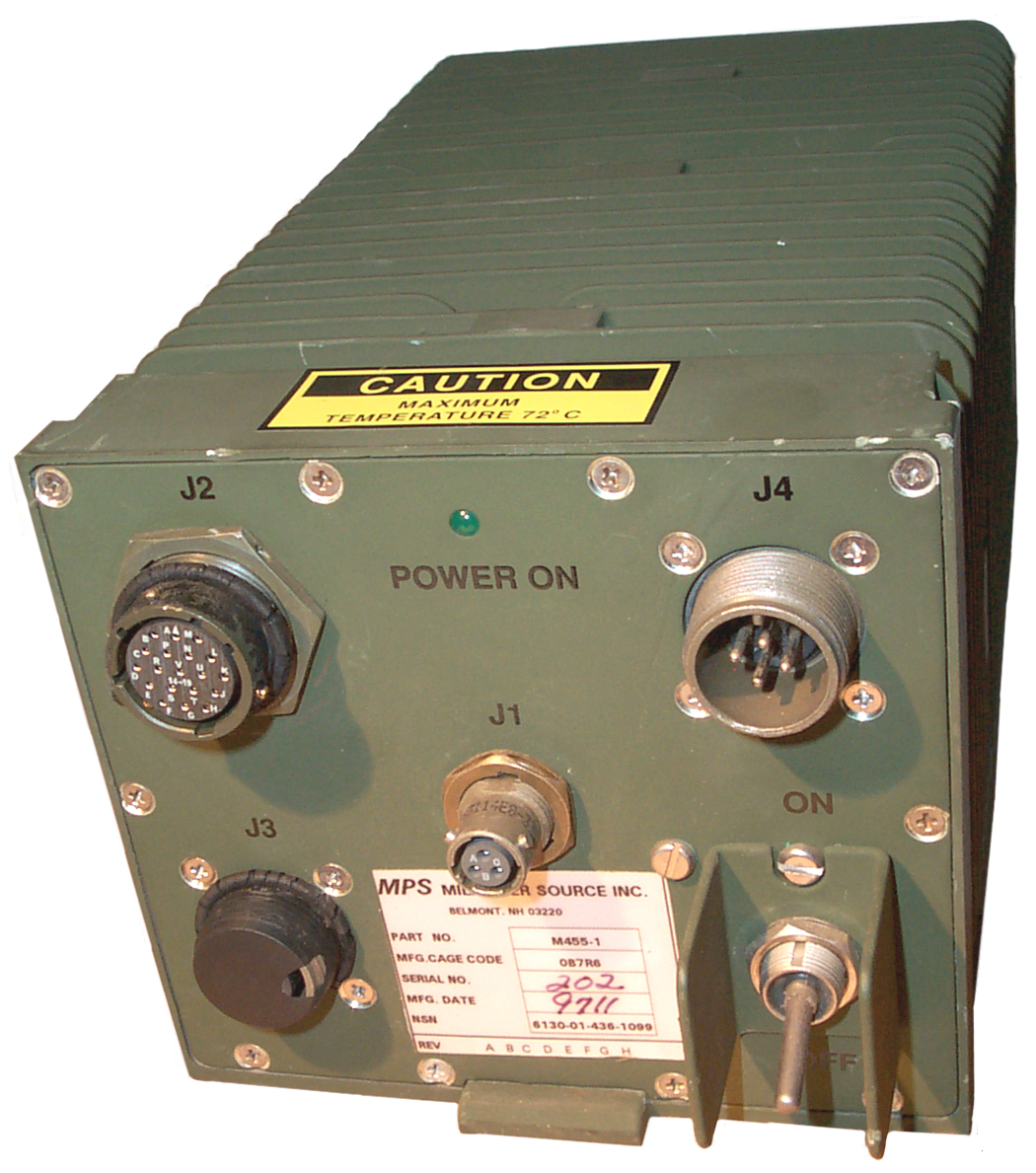
| M455-1
GRC-206 Power Source |
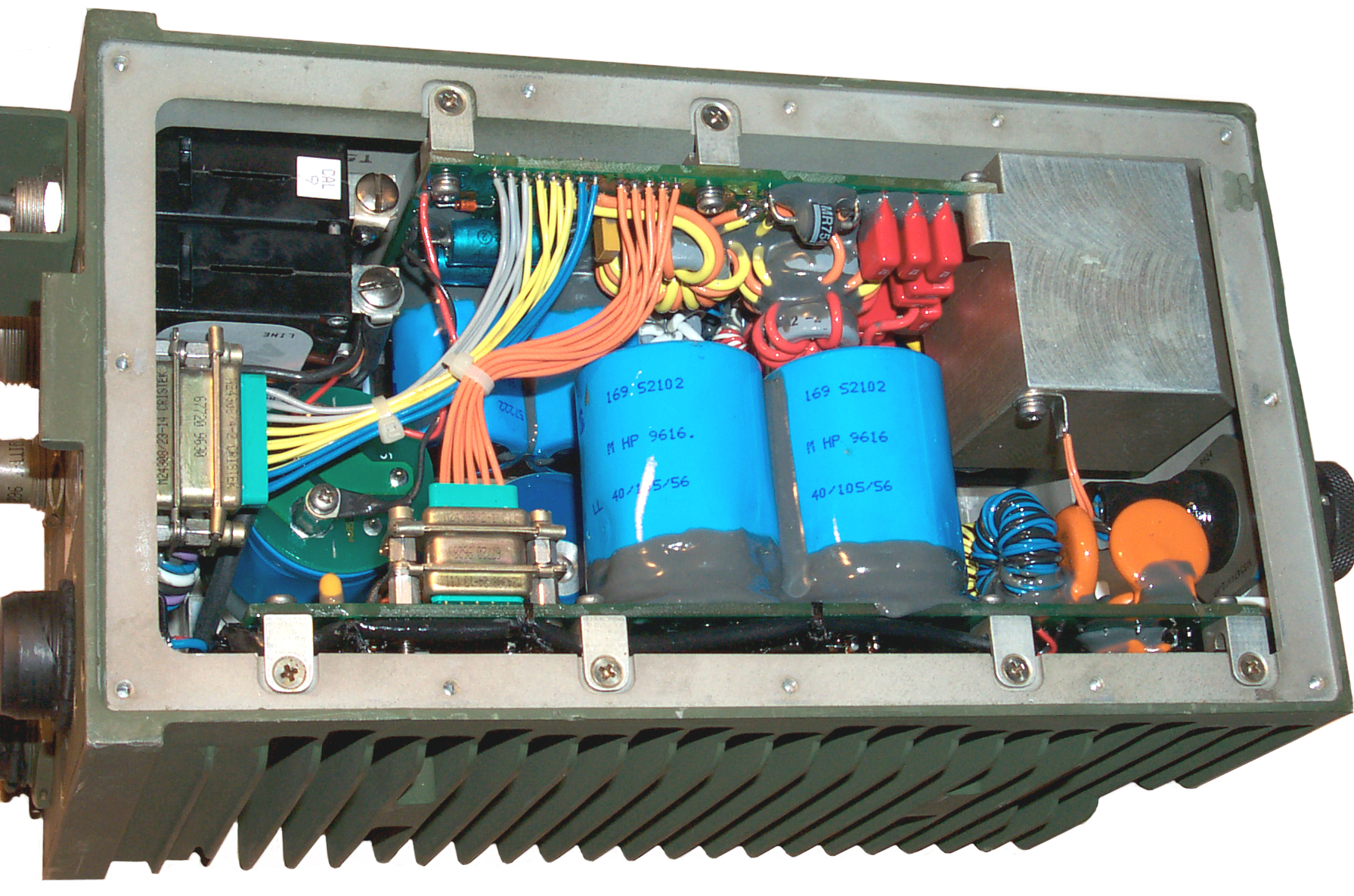
M455-1
Inside View |
Power On,
See Output Voltage Tables |
|
| PP-2953 |
PP-6224 |
M455-1 |
|
| Size |
35 x 34
x 16" |
14x12x6.75 |
5 x 5 x
9.5" |
| Volume cu in |
18,496 |
1,134 |
237 |
| Weight |
39 |
34.5 |
8 |
| Power Out |
10 A |
25A |
50 A1 |
| PMIC | Critical | ADPE | ESDC | HMIC | DEMIL | SA | SOS | AAC | QUP | UI | PRICE | SIC | CIIC | RepCode | MgmtCntrl | PhraseData |
| U | X | 0 | |
N | B | DF | FLZ | C | 1 | EA | 16,317.29 | 0 | U | T | SF8RY-N |
| Box |
Description |
Jack |
Cable Connector |
amps/ pin |
Total Amps |
| M455-1 |
+24
to 30 DC Out |
J2 |
MS3116F14-19PX | 10 |
70 |
| M455-1 | +24
to 30 DC Out |
J3 |
MS3106A14S-2P | 22 |
22 |
| M455-1 | +8 DC Out | J1 |
KTP06B8-33P | 10 |
10 |
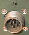
| M455-1 | +18
to 40 DC In |
J4 |
MS3106A14S-2S | 22 |
22 |
| SB-4151 | System
DC Input |
J4 or J5 | MS3106R-24-22S | 46 |
46 |
| Positive |
A B C
D J K L M |
| Nagative |
E H R
S T U V |
| ??? |
F G |
| Chassis Gnd |
N P |
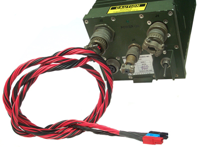
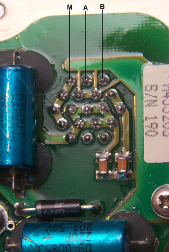
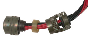 When making up this cable it's tricky to feed each wire through
the
rubber weather seal since each wire must go to the correct hole
AND can
not cross over any other wires on the way otherwise you can not
seat
the weather seal. After the cable clamp was tightened the
connector does not want to mate with the power supply. I
think
the reason may be a solder bump on a pin is getting pushed by
the
weather seal causing the pin to move just enough to by out of
line. Next step is to just pull the weather seal back and
have a
look with the stereo zoom microscope.
When making up this cable it's tricky to feed each wire through
the
rubber weather seal since each wire must go to the correct hole
AND can
not cross over any other wires on the way otherwise you can not
seat
the weather seal. After the cable clamp was tightened the
connector does not want to mate with the power supply. I
think
the reason may be a solder bump on a pin is getting pushed by
the
weather seal causing the pin to move just enough to by out of
line. Next step is to just pull the weather seal back and
have a
look with the stereo zoom microscope.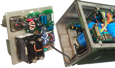 |
The flathead screws holding
on the top and front panels were probably
installed with a power screwdriver (Poz 1) so are easy to
strip the
head. Best if a drop of Kroil is placed on each
screw and allowed to
sit awhile before trying to remove them. One of the
front panel screws
was munged up. A few attempts at using just the
driver bit and a
hammer to reform the Poz 1 shape and trying to unscrew it
were
unsuccessful. But after putting a drop of Kroil then
a few whacks with
the hammer the screw was loose and could be removed using
just my
fingers on the bit (no driver needed) so it's much better
to start with
the Kroil than use it later. The D-sub connector needs to be disconnected prior to hinging out the front panel. The black wire goes to switch LINE and the red wire goes to switch LOAD and after they are disconnected the front panel is free of the chassis allowing the back of J2 to be inspected. Three pins of the DB-15 connector are used for the high current contacts, but as far as I can tell they are rated for only 5 Amps per pin allowing thus supporting only 15 Amps. The 4550 landing light is rated at 28 Volts 250 Watts, i.e. just under 9 amps so should light. |
 |
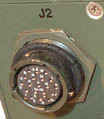
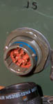
J2 Back SideThe following pins are visibily connected: C & D M, L, K & J N & P = Chassis Ground (trace under paper label with screw) R, V, U, E, S, T & H visibily isolated are: A, B, F & G = spares no connection So the wiring shown above is correct and there's no sense pins on this connector. |
| Panel Jack # |
Photo |
Panel Conn |
Panel Desc |
Cable Plug |
| J1 |
 |
MS3114E8-33S |
3
Sockets |
KTP06B8-33P |
| J2 |
 |
62GB-5067-14-19SX | 19
Sockets |
MS3116F14-19PX |
| J3 |
 |
14S-2 | 4
Sockets |
Re-Key1 MS3106A14S-2P The core is rotated |
| J4 |
 |
14S-2 | 4 Pins |
Re-Key1 MS3106A14S-2S The core is rotated |
| J5 |
 |
MS3474W12-8P | 8 Pins |
KPTO6B12-8S |
| Red
Blk-> v |
A |
B |
C |
Gnd |
| A |
- |
+8 |
+8 |
-8 |
| B |
- |
0 |
-16 |
|
| C |
- |
-16 |
||
| Gnd |
- |
| Red
Blk-> v |
A + B + C + D |
E + H + R + S + T + U + V J3-C |
F | G | J + K + L + M |
N & P gnd |
| A + B + C + D | - |
29 |
0 |
0 |
0 |
+10 |
| E + H + R + S + T + U + V = J3-C | - |
0 |
0 |
-29 |
-17 |
|
| F |
- |
0 |
0 |
0 |
||
| G |
- |
0 |
0 |
|||
| J + K + L + M | - |
+10 |
||||
| N & P - Gnd | - |
| Red
Blk-> v |
A |
B |
C |
D |
gnd |
| A |
- |
+29 |
+10 |
+10 |
|
| B |
- |
0 |
0 |
0 |
|
| C |
- |
-15 |
-15 |
||
| D |
- |
0 |
|||
| gnd |
- |